CAUTION! Parts can be damaged by electrostatic discharge. Keep parts in their containers until needed. Ensure that you are properly grounded when touching static-sensitive components. HP StorageWorks Enterprise Modular Library E-Series 71e Getting Started 1 Unpack the library 5 4 3 2 2 Prepare the rack WARNING! Consider the library’s weight and the weight of the other components in the rack when deciding where to place the library in the rack.
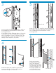
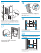
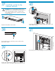
3 5 front vorder seite anterior recto fronte voorka nt 8U 4U HP Sto rageW EML ser orks ies tap e library Rear of rack AH062-96 004 Use the template shipped with the library to mark the front and back of the rack with the locations of the mounting hardware. If your library contains LTO4 tape drives or if you plan to add them later, leave an additional 1U of space above the template in which to install the switch.
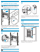
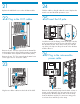
7 Install the 8U base module 9 WARNING! The 8U base module weighs 27 kg (60 lb). Use two people and a cart, tabletop, or mechanical device to lift, position, and secure the 8U base module. At the front of the library, turn the center-door knob onequarter turn counterclockwise and open the center door of the library. 10 Using two people, lift the 8U base module into position in the rack. The two tabs on each side of the 8U base module fit over the rails. Slide the 8U base module half way into the rack.
11 14 Install the 4U base module WARNING! The 4U base module weighs 12 kg (27 lb). Be careful when lifting. Use a cart, tabletop, or mechanical device to lift, position, and secure the module. Open the load port door on the 8U base module. Inside the front of the library, press the load port door latch to open the load port door. 12 Remove the cover from the left side of the 4U base module. To remove the cover, loosen the bottom thumbscrew.
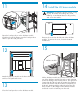
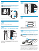
16 18 At the front of the library, remove the 4U blank cover from the 4U base module. Push down and pull the top of the 4U blank cover away from the front of the library. Lift the cover off. Open the center doors on the two modules. Align the tongue of the lower door with the groove in the upper door. Carefully slide the 4U base module into the rack until the doors are engaged. 19 17 Attach the 4U base module to the front of the rack with four T-25 panhead screws.
21 24 Replace the 4U blank cover on the 4U base module. Fold the cables so they fit under the covers. Replace the metal cover and the black protective cover. 22 Plug in the OCP cables 25 Insert the lift pole 1 2 Inside the front of the library, insert the lift pole onto the pole mount at the lower left corner of the back wall of the 4U base module. Press down on the pole until the top of the pole slips into the pole mount in the 8U base module above it.
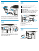
27 30 WARNING! Before doing this step, make sure the main power switch is Off and the 8U base module is not plugged in. Pull the ribbon cable out of the 8U base module. Plug the ribbon cable into the 4U base module. Plug in the two ends of the power cable. 31 28 Replace the arrays inside the library. 29 Plug in the interconnect cable Install the cover from the 4U base module (removed in step 14) onto the two modules. Tighten the two thumbscrews to secure the cover.
33 35 Latch 2 1 Make sure the robotics unit is properly installed: The guide rail fits into the alignment slot. The tabs on the bottom of the door of the robotics unit are behind the faceplate. The latch on the door of the robotics unit is fully engaged and secure. The latch on the right side of the robotics unit is fully engaged and you cannot move the robotics unit. The ratchet tool on the upper-right corner of the robotics unit is pushed in completely.
the switch for the 37 Install internal network 40 CAUTION! Do not connect this switch to your local LAN. It is for internal library communication only. Connecting this switch to a LAN could cause library components to perform incorrectly or report failures. Attach the brackets to the switch. Insert the switch into the library. Attach the switch to the rack with the screws. 38 41 Connect the power cord to the power socket on the back of the switch.
42 Install the tape drives 44 26 NOTE: HP recommends that you install tape drives from top to bottom with no gaps between them. Attach the cable clamps to the right rear rack at the positions 37T, 26T, and 15T. Use these cable clamps to route the tape drive Ethernet cables. At the rear of the library, insert a tape drive into an empty drive bay. Tighten the thumbscrew to attach the tape drive to the drive bay. Repeat for each tape drive.
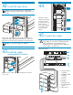
LTO4 tape drives 1 Plug an Ethernet cable (included) into the Ethernet port on the interface controller (middle card) and into the TO FIBRE CHANNEL CONTROLLERS port on the Interface Manager card (bottom card in the card cage). 2 Plug an FC cable (not included) into the FC0 port on the interface controller (middle card) and into either the host bus adapter (HBA) port on a host or into an FC switch that is connected to the host. 3 4 5 6 8 9 8 7 10 1. Switch for the internal network 2.
46 Attach the bar code labels to the tape cartridges 48 Power on the library CAUTION! Handle tape cartridges with care. Do not drop or mishandle them, or place them near sources of electromagnetic interference. Rough handling can damage the tape cartridge making it unusable and potentially hazardous to the tape drives. CAUTION! The misuse and misunderstanding of bar code technology can result in backup and restore failures.
51 If this is the first time the library has been powered on after delivery, or if a new interface controller was installed, configure the interface controller so that it is recognized by the Interface Manager card. 54 Configure the library 3 Wait several seconds and then turn on the power switch again. NOTE: The library requires up to fifteen minutes to initialize and do an inventory. While the library is doing an inventory, continue with the next step.
Identify the parts of the library 1. Customer reserved space. If your library contains LTO4 tape drives, this space contains the switch for the internal network. 2. 8U base module 3. 4U base module 4. Robotics unit 5. Viewing windows 6. Operator control panel (OCP) 7. 5-Cartridge load port 8. 4U blank cover 1 4 5 2 7 5 3 6 8 Front view 1 26 2 3 5 11 6 9 10 7 8 12 4 Rear view 1. Customer reserved space 2. Switch for internal network (in libraries with LTO4 tape drives only) 3.
Printed on at least 50% total recycled fiber with at least 10% post-consumer paper © Copyright 2006-2007 Hewlett-Packard Development Company, L.P. Second edition (September 2007) Printed in the US. www.hp.com Part no.