
HP StorageWorks Encryption SAN Switch quick start instructions (AR944-90001, March 2009)

HP StorageWorks
Encryption S AN S w itch quick
start instructions
© Copyright 2009 Hewlett-Packard Development Company, L.P.
First ed
ition: March 2009
The information in this document is subject to change without notice.
Printed in the U.S.
www.hp.
com
*AR944-90001*
Overview
Read these inst
ructions to set up and configure the HP StorageWorks
Encryption SAN
Switch.
These instruct
ions prov ide basic configuration steps. Fo r detailed rack
mount and configuration instructions, download the HP StorageWorks
8Gb SAN Switch
hardware reference guide and the HP StorageWorks
Fabric OS 6.2 administrator guide from the storage section of the
following HP
website: h
ttp://www.hp.com/support/manuals
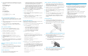
Figure 1 shows the port side of the Encryption SAN Switch.
Figure 1 Port side of the HP StorageWorks Encryption SAN
Switch
1. Status LED
5. RJ-45 GE management port
2. Power LED
6. RJ-45 serial console port
3. RJ-45
GE ports (for clustering
and re-
keying)
7. U S B p o r t
4. Smart Card reader 8. Fibre Channel ports (0–31)
Verify the carton contents
Verify that the carton contains the following:
• One Encryption SAN Switch with two power supplies and three fan
assemblies.
• One accessory kit with the following items:
• Four rubber mounting feet (for standalone setup on a flat surface)
• Two grounded power cords
• Power distribution unit (PDU) power cords
• One serial cable, approximately 3 meters (10 feet)
• HP StorageWorks product documentation, including HP
StorageWorks SAN Switch Rack M ount Kit installation
instructions, Read Me First, Safety Guides, User License, and
Warranty
• HP StorageWorks B-Series Data Center Fabric Manager CD
Ve
ri fy installation requirements
To set up the Encryption SAN Switch for the first time, you will need:
• Workstationwithaninstalledterminalemulator,suchas
HyperTerminal
• T wo unused IP addresses and corresponding subnet masks and
gateway addresses: one IP address for the cluster interconnect;
anotherIPaddressforthemanagementport
• Serial cable (supplied with the switch)
• Ethernet cable
• Access to an FTP server for backing up the switch configuration
(optional)
• SFP transceivers and compatible cables
IMPORTANT:
Order SFP transceivers separately. The Encryption SAN Switch
only supports HP transceivers labeled “B-Series FC SFP".
Check h
ttp://ww w.hp.com for more information on supported
transceivers.
Site plan
ning
To ensure adequate cooling, install the switch with the nonport side
(which co
ntains the air intake vents) facing a cool air aisle. Verify
that the a
mbient air temperature does not exceed 40° Celsius (104°
Fahrenh
eit) and that the ambient humidity remains between 20% an d
85% whil
e the switch is operating.
To install a nd operate the switch successfully, ensure that:
• The primary AC input is 90–264 VAC (the switch autosenses input
voltage), 47–63 Hz.
• The primary outlet is wired correctly , protected by a circuit breaker,
and grounded in accordance with local electrical codes.
• The supply circuit, line fusing, and wire size are adequate, as
spec
ified by the electrical rating on the switch namep late.
For specificpowersupplyinformation,seetheHP StorageWorks 8Gb
SAN S
witch hardware reference guide.
Rack mount guidelines
HP strongly recommends installing the switch in one of the following
optional HP custom racks:
• HP StorageWorks System/e Rack
• HP StorageWorks 9000 Series Rack
• HP StorageWorks 10000 Series Rack
• HP StorageWorks 10000 G2 Series Rack
Follow these guidelines:
• Plan a rack space that is 1 or 2 rack units high (4.44 cm/1.75 in),
48.3 cm (19 in) wide, and up to 61 cm (24 in) deep.
• Ground all equipment in the rack through a reliable branch circuit
connection, a nd maintain ground at all times. Do not rely on a
secondary connection to a branch circuit, such as a power strip.
• Ensure that airflow and temperature requirements are being met,
especially if the switch is installed i n a closed or multi-rack assembly.
• Verify that the additional weight of the switch does not exceed the
rack’s weight limits or unbalance the rack.
• Secure the rack to ensure stabilit y in case of unexpected movement.
For additional installation, electrical, environmental, and other
considerations, see the HP StorageWorks 8Gb SAN Switch hardware
reference guide.
Install a standa
lone switch
1. Unpack the swit
ch and verify the contents as described in Verify
the carton cont
ents are included.
2. Apply the adhe
sive rubber feet to prevent the switch from sliding off
the supporting s urface.
a. Clean the indentations at each corner of the bottom of the
switch to ensure that they are free of dust or other debris that
might lessen the adhesion.
b. Withtheadhesivesideagainstthechassis,placeonerubber
foot in eac
h indentation and press into place.
3. Place the s
witch on a flat, sturdy surface.
Setupinasingle-switchconfiguration
Tosetupinasingle-switchconfiguration, you will need:
• Standard screwdriver
• Fixed IP address (IPv4 or IPv6) for the switch (no DHCP server)
• Subnet mask value
• Default gateway value
• World Wide Name (WWN), located on the switch ID pullout tab
• Ethernet connection (hub or switch)
• Host computer with a host bus adapter (HBA) installed.
This computer should be on the same subnet as the switch. Do not
run the host computer in th e SAN.
• Ethernet and Fibre Channel cables
• Disk array with Fibre Channel por ts
• Browser that allows pop-up windows
Power on the switch
1. Connect the power cords to both power supplies and then to power
sourcesonseparatecircuitstoprotectagainstACfailure.
2. Pow
er on the power supplies by flipping both AC switches to the
“1”
position. The power supply LEDs are amber until power-on
sel
f-test (POST) is complete, and then change to green.
3. After POST is complete, verify that the swi tch power LED on the port
side is green and the status LED is off.
IMPORTANT:
Do not connect the switch to the network until the IP address is
set .
Connect the serial cable
1. Remove the plug from the serial port and connect th e serial cable
provided with the switch.
2. Connect the c able to an RS-232 serial port on th e workstation.
IftheserialportisRJ-45insteadofRS-232,removetheadapteron
the end of the serial cable and insert the exposed RJ-45 connector
into the RJ-45 serial port.
3. Disable any serial communication programs running on the
workstation.