HP 30-10022-01 loop switch user guide Part number: 5697–5674 First edition: June 2006
Legal and notice information © Copyright 2006 Hewlett-Packard Development Company, L.P. Hewlett-Packard Company makes no warranty of any kind with regard to this material, including, but not limited to, the implied warranties of merchantability and fitness for a particular purpose. Hewlett-Packard shall not be liable for errors contained herein or for incidental or consequential damages in connection with the furnishing, performance, or use of this material.
Contents 1 Introduction . . . . . . . . . . . . . . . . . . . . . . . . . . . . . . . . . . . . . . . . . . . . . . . . . . . . . . . . 5 Overview. . . . . . . . . . . . . . . . . . . . . . . . . . . . . . . . . . Features . . . . . . . . . . . . . . . . . . . . . . . . . . . . . . . . . . HP technical support . . . . . . . . . . . . . . . . . . . . . . . . . . HP-authorized reseller. . . . . . . . . . . . . . . . . . . . . . . Helpful web sites . . . . . . . . . . . . . . . . . . . . . . . . . . .. .. ..
C Event Messages . . . . . . . . . . . . . . . . . . . . . . . . . . . . . . . . . . . . . . . . . . . . . . . . . . . 45 D AL_PA Cross References. . . . . . . . . . . . . . . . . . . . . . . . . . . . . . . . . . . . . . . . . . . . . . 49 Glossary . . . . . . . . . . . . . . . . . . . . . . . . . . . . . . . . . . . . . . . . . . . . . . . . . . . . . . . . . . 51 Index . . . . . . . . . . . . . . . . . . . . . . . . . . . . . . . . . . . . . . . . . . . . . . . . . . . . . . . . . . . . .
1 Introduction This guide describes how to install and manage the 30-10022-01 loop switch. Overview The 30-10022-01 loop switch is a 12-port, speed agile switch. Enclosed in a 1U, half-rack form factor enclosure, the switch is controlled by firmware loaded into the on-board flash memory. The switch is designed as a central interconnect following the ANSI FC-AL standard. Devices are connected to the switch through Small Form-factor Pluggable (SFP) transceivers and cables.
Features The 30-10022-01 loop switch incorporates the following features: • High Performance Fibre Channel Switching: • 2Gb/s or 1Gb/s auto-detection per port • 12-port design with embedded SerDes • Multiple simultaneous conversations between ports • Traffic routed directly to destination ports • Fairness and prioritization ensure that all devices have guaranteed access, or explicitly have prioritized access over other devices in a system • Automatic port configuration simplifies configuration and setup pro
2 Switch Installation Installation Preparation After receiving the switch, perform the following steps to ensure that the switch and other contents arrived safely. To unpack the switch: 1. Inspect the outer shipping container for any damage that may have occurred in shipping. Report any sign of damage to the appropriate shipping agency. 2.
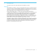
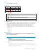
Figure 1 Switch View Depicting Ethernet, Port, and System LEDs Ethernet LEDs 2 1 100-240V~, 50/60 H Z 3 4 5 6 POWER 10101 FAULT TEMP 7 8 9 10 11 12 System LEDs Port LED Ethernet LEDs The Ethernet LEDs indicate the network connection status: Figure 2 Ethernet LEDs Ethernet Activity Ethernet Link Ethernet LEDs Indication Ethernet Activity (green LED) • When flashing, the Ethernet port is receiving data. • When flashing rapidly, the traffic level is high.
Port LED The Port LED indicates a port’s status. Figure 4 Port LEDs 1 2 3 4 5 6 7 8 9 10 11 12 Port 7 LED Port 2 LED Port LED Indication Off SFP is not installed in the port. On (green) Normal port operational status when an SFP is installed and a link has been established. On (yellow) The port has an SFP installed but a link has not been established. Flashing (green) Activity. Data is being transferred between the port and device.
• If the SFP has a small plastic slider on the top or bottom, remove the cable from the SFP and then push in the slider and hold while pulling out the SFP. • If the SFP has a bale (small metal clasp), remove the cable from the SFP and then unlatch, pivot, and pull the bale. Attaching a Device to the Switch To attach a device: 1. Make sure that the device is FC-AL compatible. 2. Attach a cable to the device. 3. Attach the other end of the cable to an SFP. 4.
Booting the Switch and Attached Devices The following procedure is recommended when booting the switch and attached devices. To boot the switch and attached devices: 1. Power on the storage devices. 2. Insert the plug end of the switch’s power cord to a properly grounded power source. 3. Insert the power cord’s IEC connector end into the switch’s power receptacle. The switch powers on and runs Power-On Self-Test (POST) diagnostics to verify the fundamental integrity of the switch ports.
Switch Installation
3 Switch Management The switch incorporates two distinct interfaces for managing and monitoring purposes: • The Web Manager interface provides an intuitive graphical user interface that enables users to quickly check switch status or modify switch settings in a visual environment. • The Command Line Interface (CLI) provides flexibility and additional functionality for advanced users. For a list of CLI commands, see : CLI Quick Reference on page 43.
9. Type save and press ENTER. 10. Type root reset and press ENTER. 11. Type y and press ENTER to reset the switch. 12. Attach the computer to the switch’s 10/100 Ethernet connector by doing one of the following: • Attach an Ethernet RJ-45 cross-over cable directly between the computer and the switch. • Attach two Ethernet RJ-45 twisted pair cables from the computer and the switch into an operational Ethernet patch panel or hub.
To return to this page at any time, click Switch Information on the navigation menu. Figure 5 Web Manager interface Command buttons Navigation menu Displayed information area NOTE: The Web Manager’s appearance and information depends on the switch’s active firmware version and may change without notice in subsequent firmware versions. The Web Manager interface consists of a series of command buttons, a navigation menu, and the displayed information area.
A message box is displayed confirming the change to the switch’s configuration and that you are logged in as an administrator (“admin”). Figure 6 Submit confirmation message box 3. Click OK. The Enter Network Password box is displayed. Figure 7 Enter Network Password message box 4. Ensure that “admin” is entered for the User Name, and type the password in the Password field. The default password is “password”.
1. Click Reset. A message box confirming the switch reset is displayed. 2. Click OK. The switch will reset. Help The Web Manager’s Help button provides a link to online product documentation and firmware downloads available on the HP Web site (www.hp.com/go/852switch). To access documentation and firmware, click Help. Navigation Menu The navigation menu provides a list of options for configuring and monitoring the switch. Clicking a menu item displays the selected Web Manager page.
NOTE: To view the current page without displaying the submission results, click the View page without submission results link. See “Changing the Password” on page 38 for additional information. Step 3: Change the Switch Name While not required, entering a switch name is recommended for identification and troubleshooting purposes. To enter a switch name: 1. Click Switch Configuration. The Switch Configuration page is displayed. 2. Under Switch Identification, enter the switch’s name in the Name text box. 3.
Managing and Monitoring the Switch The 30-10022-01 loop switch provides several options for managing, configuring, and monitoring the switch to meet the needs of the network environment. This section describes the features and functionality of each Web Manager page available in the navigation menu. Viewing Switch Information The Web Manager’s home page is the Switch Information page.
Item Status Indicators Serial Number A unique identification number assigned to each switch at the factory. Hardware version The hardware version of the switch. Switch up-time The duration of time that the switch has been operational. If the switch is rebooted or power is cycled, this value is reset. Port Utilization and Health This part of the Web page displays each port number, the port’s current health status, and a vertical bar indicating the port utilization.
Configuring Switch Settings Several switch configuration settings may be changed to customize the switch to the network environment. The Switch Configuration page displays general switch settings, switch identification information, configuration file information, and the SCSI Enclosure Services (SES) AL_PA setting. To make a change to the current switch configuration, you must know the switch password (the switch prompts for the password before accepting changes to any configuration settings).
configuration settings. The “current” settings display the settings that the switch is using. The “Settings after Next Reset” are the network settings that are configured for the next switch reset. Setting Description DHCP For DHCP-enabled environments, you can enable the switch to acquire an IP address from a DHCP server automatically. This feature is disabled by default. Ethernet IP address The IP address for the switch. Ethernet netmask The IP netmask address for the switch.
Restoring the Factory Default Settings If necessary, the switch settings can be reset to their factory default values; however, the network configuration settings are retained. To restore the factory default configuration: 1. Under Configuration File, click Reset to Default Settings. A message box is displayed confirming the request. 2. Click OK to restore the factory default configuration and reset the switch.
The Event Log page is displayed. Figure 10 Event Log page The last time the event log was polled is displayed at the top of the page. Setting the Fault LED Threshold The Fault LED threshold sets the minimum severity level at which an event message will trigger the Fault LED to light. The default value is “critical”. To change the Fault LED threshold: 1. Next to Fault LED Threshold, click the drop-down box to display a list of valid severity levels. 2. Select the new value in the drop-down box. 3.
2. Click OK to delete the event log. The event log is cleared out and a new event message is displayed reporting that the event log has been cleared. Clearing the Fault LED To clear the Fault LED after an event message has triggered it: 1. Click Clear Fault LED. A message box is displayed confirming the request. 2. Click OK to clear the Fault LED. The switch’s Fault LED should turn off. Saving the Event Log To export the event log to the host system: 1. Click Save event log file to host.
The standard reporting groups are: Reporting Group • • • • • • • • • • • • • • • • • • • • • • • • 0 – kernel messages 1 – user-level messages 2 – mail system 3 – system daemons 4 – security/authorization messages 5 – messages generated internally by syslogd 6 – line printer subsystem 7 – network news subsystem 8 – UUCP subsystem 9 – clock daemon 10 – security/authorization messages 11 – FTP daemon 12 – NTP subsystem 13 – log audit 14 – log alert 15 – clock daemon 16 – local use 0 17 – local use 1 18 – loc
Viewing Port Information The Port Information page displays the ports, their current health, the AL_PAs currently assigned to each port, and the utilization for each port. Port utilization measures the amount of traffic passing through a port over a period of time. For example, if an initiator is transmitting data to a target, the initiator port displays a transmit (Tx) port utilization value (%) while the target port displays a receive (Rx) port utilization value.
Configuring Port Settings The Port Configuration page displays the ports, their current health status, their current operating speed, and SFP serial identification information. To view the Port Configuration page, click Port Configuration. Figure 12 Port Configuration page Field Description Port Displays the current health of the port. See “Port Utilization and Health” on page 20 for additional information on port health. Enabled Indicates if the port is enabled. The default setting is “Yes”.
1. Click Port Configuration. 2. Select the specific port’s desired speed from the drop-down menu. Setting Description 1 Gb/s Set port speed to 1.0625 Gb/s. 2 Gb/s Set port speed to 2.125 Gb/s. 4 Gb/s Set port speed to 4.25 Gb/s (not supported) Auto Automatically detect and set port speed. 3. Click Submit.
Title Description Force Reset A single-instance operation that places a port in bypass mode and then immediately sets the port to auto-detect to re-insert the port. This feature may be used to diagnose device problems when a device is locked up or experiencing a high number of failures on a port. Clearing Insertion Counters To clear the counters: 1. Click Clear Insertion Counters. A message box is displayed confirming the request. 2. Click OK to clear the insertion counters.
Viewing Advanced Statistics This page displays information that may be used for the advanced troubleshooting of switch-related issues. To view the advanced statistics, click Advanced Statistics. The Advanced Statistics page appears. Figure 14 Advanced Statistics page The Advanced Statistics page displays the following information: Diagnostic Description Low-level Link Low-level FC-1 traffic information. High-level Link High-level FC-1 traffic information.
The Low-level link statistic page displays the following information: Figure 15 Advanced Statistics Low-level Link page 32 Diagnostic Description Sync Loss The number of times loss of word synchronization has occurred on the port for a specified time. Synchronization loss occurs when the port stops receiving a signal for a period of time. Possible causes include: • Poor connections or signal strength • Rogue devices • Intermittent hardware failures or line conditions.
The High-level link statistic page displays the following information: Figure 16 Advanced Statistics High-level Link page Diagnostic Description Open-CLS Rx The counter for the number of CLS received to OPNs sent. This occurs when the target device refuses to accept an OPN. If the counter increases, attempts to send data out the port will be affected and performance will begin to degrade. This can be a sign of congestion or a slow device.
The Frame Counts statistic page displays the following information: Figure 17 Advanced Statistics Frame Counts page Diagnostic Description CRC Errors The number of Cyclic Redundancy Check (CRC) errors that are detected in frames passing through the port since the last switch reset or since the counters were cleared.
Figure 18 Advanced Statistics Class 2 Traffic page Diagnostic Description Frames Rx The number of frames received for a particular class. For the All Traffic statistic page, this is the total number of frames received from all classes. Frames Tx The number of frames transmitted for a particular class. For the All Traffic statistic page, this is the total number of frames transmitted from all classes. K-octets Rx The number of Kilo-octets received for a particular class.
Managing Firmware The Firmware page displays the current and alternate firmware versions, enables users to select which firmware version to run the next time the switch is reset, and provides a means to load new firmware on the switch. To check for new firmware on the Emulex Web site, click Help. To view the firmware, click Firmware. The Firmware page is displayed. Figure 19 Firmware page Loading New Firmware To load new firmware on the switch: 1.
Configuring Date and Time Settings The Switch Date and Time page displays the switch’s current date and time. During the initial Web Manager session, the date and time for the switch are set based on the host system’s current settings. To set the date and time settings: 1. Click Date and Time. The Switch Date and Time page is displayed. Figure 20 Switch Date and Time page 2. Enter the new date and time settings in the New Date and Time text box. 3. Click Submit.
Changing the Password The Change Password page enables you to change the password for modifying the switch’s configuration. The same password is used to access both the Web Manager and the CLI. Note: Until the default switch password is changed, any user with knowledge of the default password can make changes to the switch’s configuration. To change the password: 1. Click Change Password. The Change Password page is displayed. Figure 21 Change Password page 2.
4 Technical Reference Troubleshooting Device Connections Problem Recommended Action SFP installed in one or more ports, but LED is not lit 1. Verify that the power cord is firmly seated into switch and is connected to a properly earthed receptacle (outlet). 2. Check the Power LED to ensure that the switch is turned on. 3. Verify that the SFP is firmly seated. SFP installed, but only yellow LED is lit 1. Make sure that the device is powered on and operating properly. 2.
Port Bypass Conditions and Recovery 40 Operational Condition Recovery Rx_los is asserted by an SFP/GBIC The port stays bypassed until rx_los is de-asserted. At that time, the port insertion will be automatically retried. The port continues to stay bypassed until the port can pass the port insertion criteria. Tx_fault is asserted by an SFP/GBIC The port stays bypassed until tx_fault is de-asserted. At that time, the port insertion will be automatically retried.
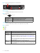
A Specifications Switch Specifications Specification Value Number of Ports 12 Operating Rate All ports operate independently at 1.0625 or 2.125 Gb/s Port Media Type SFP optical or copper based Enclosure 1U half-rack form-factor Management Interface Fibre Channel, RS-232, or 10/100 Ethernet EU Compliance EU directive 2002/95/EC Configurability Management interface configurable Power On Selftest (POST) Yes Dimensions 8.5" x 1.73" x 14.
Specifications
B CLI Quick Reference Connecting to the CLI The Command Line Interface (CLI) can be accessed through a network interface using a terminal emulation program, such as telnet, or through the serial interface from a local computer using a utility program, such as HyperTerminal. Refer to the HP EVA 4000/6000/8000 30-10022-01 loop switch CLI reference guide for detailed descriptions of CLI commands and usage. To connect through a network interface: Use a network terminal emulation program.
Frequent Switch Configuration Tasks A list of frequent switch configuration-related tasks is provided below. The list displays the task and the corresponding CLI command.
C Event Messages The event messages for the 30-10022-01 switch are listed below. A message’s applicable severity level, as defined below, is also provided. Severity Level Severity 1 EMERGENCY 2 ALERT 3 CRITICAL 4 ERROR 5* WARNING 6 NOTIFY 7 INFO Description Immediate action required; system failing. Unrecoverable condition reported; major event in progress. Event failed with possible loss of integrity. Condition failed; action required. Failed event occurred; no action required.
Message Number Severity 11 ALERT A test failure has occurred on the internal SPI bus. This indicates a hardware failure in the unit. Contact technical support and report the following information: a receive failure on chip has occurred. 12 ALERT A test failure has occurred on the internal SPI bus. This indicates a hardware failure in the unit. Contact technical support and report the following information: a router delivery failure on chip has occurred.
Message Number Severity 47 INFO Description The event severity filter has been changed to . Note: This event is automatically displayed in the event log, regardless of the current event log or Fault LED threshold setting. 48 INFO The event fault LED threshold has been changed to . Note: This event is automatically displayed in the event log, regardless of the current event log or Fault LED threshold setting. 49 INFO The event log has been cleared.
Event Messages
D AL_PA Cross References Arbitrated Loop Physical Addresses AL_PA AL_PA ID AL_PA AL_PA ID AL_PA AL_PA ID (hex) (hex) (decimal) (hex) (hex) (decimal) (hex) (hex) (decimal) EF E8 E4 E2 E1 E0 DC DA D9 D6 D5 D4 D3 D2 D1 CE CD CC CB CA C9 C7 C6 C5 C3 BC BA B9 B6 B5 B4 B3 B2 B1 AE AD AC AB AA A9 A7 A6 A5 00 01 02 03 04 05 06 07 08 09 0A 0B 0C 0D 0E 0F 10 11 12 13 14 15 16 17 18 19 1A 1B 1C 1D 1E 1F 20 21 22 23 24 25 26 27 28 29 2A 0 1 2 3 4 5 6 7 8 9 10 11 12 13 14 15 16 17 18 19 20 21 22 23 24
AL_PA Cross References
Glossary ABTS Abort Basic Link Service. AL_PA or Arbitrated Loop Physical Address A one-byte value used to identify a port in an Arbitrated Loop topology. The value of the AL_PA corresponds to bits 7:0 of the 24-bit Native Address Identifier. CLI Command Line Interface. A command-based interface for configuring, managing, and displaying switch settings. CLS Close Primitive Signal. Sent by a port that is currently communicating on the loop, to close communication to another port.
SES SCSI Enclosure Services. A subset of the SCSI protocol used to monitor temperature, power, and fan status for enclosed devices. SFP Small Form-Factor Pluggable transceiver. These transceivers are fully compliant with FC-PI and MSA standards and occupy less than half the board space of the existing GBIC products. SOC Switch On a Chip SOF Start Of Frame. A group of ordered sets used to mark the beginning of a frame.
Index A L AL_PA Cross References 49 authorized reseller, HP 6 LEDs ethernet 8 port 9 Power 8 switch 7 system 8 System Fault 8 Temp Fault 8 logging in and out 43 C CLI commands 44 connecting 43 frequent tasks 44 logging in and out 43 configuration files 22, 36 configuring network interface 13 switch settings 21 Web Manager 14 D date and time settings 37 desktop installation 7 diagnostics port 29 displaying event log 23 port diagnostics 29 port information 27 switch status 19 E ethernet LEDs 8 event log
configuration files 22, 36 date and time settings 37 event log 23 event log messages 45 features 6 firmware 36 identification 21 initial setup 17 installation 7 LEDs 7 management 13, 19 network settings 21 operating conditions 41 overview 5 package contents 7 port diagnostics 29 port information 27 powering on 11 settings 21 specifications 41 status 19 unpacking 7 system LEDs 8 T temperature 41 terms see glossary 51 time and date settings 37 troubleshooting 39 U UL guidelines 7 unpacking the switch 7 V v