HP 30-10022-01 loop switch CLI reference guide Part number: 5697–5675 First edition: June 2006
Legal and notice information © Copyright 2006 Hewlett-Packard Development Company, L.P. Hewlett-Packard Company makes no warranty of any kind with regard to this material, including, but not limited to, the implied warranties of merchantability and fitness for a particular purpose. Hewlett-Packard shall not be liable for errors contained herein or for incidental or consequential damages in connection with the furnishing, performance, or use of this material.
Contents 1 Introduction . . . . . . . . . . . . . . . . . . . . . . . . . . . . . . . . . . . . . . . . . . . . . . . . . . . . . . . . 5 Getting Started . . . . . . . . . . . . . . . . . . . . . . . . . . . . . . . . . . . . . . . . . . . . . . . . . . . Connecting through a Serial Interface. . . . . . . . . . . . . . . . . . . . . . . . . . . . . . . . . Logging In and Out . . . . . . . . . . . . . . . . . . . . . . . . . . . . . . . . . . . . . . . . . . . . . Initial Switch Configuration . . . . . . . .
Displaying Port Insertion Counters (show/prtctrs) . . . . . . . . . . . . . . . . . . . . . . . . . . . . . . . . . . . . . . . Displaying Port Utilization Information (show/prtutilization) . . . . . . . . . . . . . . . . . . . . . . . . . . . . . . . Clearing Counters (show/clrctr). . . . . . . . . . . . . . . . . . . . . . . . . . . . . . . . . . . . . . . . . . . . . . . . . . . Displaying System Information (show/sysinfo) . . . . . . . . . . . . . . . . . . . . . . . . . . . . . . . . . . . . . . . . .
1 Introduction This guide describes how to configure and manage a 30-10022-01 loop switch using the Command Line Interface (CLI). Getting Started This section explains how to connect to the CLI through a serial interface, log into the switch, and navigate through the CLI command menu. Connecting through a Serial Interface The switch may be accessed through the serial interface (RS-232 serial port) to manage the switch from a local computer.
For access over the network using Telnet, from a command line prompt, type telnet and press ENTER. 2. Type the password at the prompt and press ENTER. The default password is “password”. To log out of the CLI: Type lo and press ENTER, or exit the terminal session. NOTE: The CLI will automatically log you out after 60 minutes of inactivity.
To navigate from one menu to another menu: Type in the complete menu command and press ENTER. For example, in the Firmware menu, type root show sysinfo at the command prompt and press ENTER. The system information menu is displayed. To cancel a prompt or input request: Press ENTER. If an incorrect command is entered, the “ERROR: Invalid Command” message is displayed. If this message is displayed, ensure the correct command syntax is being entered and try again.
To change the default gateway setting: 1. From the Network Configuration menu (config/network), type gateway and press ENTER. 2. Type the new default gateway setting and press ENTER. Changing the Switch Password NOTE: Until the default switch password is changed, any person with knowledge of the default password can make changes to the switch’s configuration. To change the password: 1. From the Configuration menu (config), type password and press ENTER. 2. Type the current password and press ENTER.
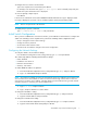
CLI Command Reference Diagram The diagram below displays the available CLI commands and their hierarchical structure. root --> 1. config --> 1. sys --> 1. time 2. name 3. location 4. contact 5. events 6. sev 7. fault 8. evclr 9. clrled 10. syslog 11. cfgdump 12. cfgload 13. .. 14. ? --> 1. beacon 2. enable 3. speed 4. lip 5. .. 6. ? 1. show 2. dhcp 3. ip 4. mask 5. gateway 6. reset 7. .. 8. ? 1. galpa 2. prtctrs 3. clrctr 4. beacon 5. .. 6. ? 3. show --> 1. events 2. speeds 3. prtctrs 4.
Display the Current Menu (?) This command displays the current menu. In addition, if you press ENTER at the command prompt, the current menu is displayed. To display help for specific command: Type ? and press ENTER. Enter the command using one of the following methods: • Type the actual command text. For example, under the Show menu, to view help for the sysinfo command: type ? sysinfo and press ENTER. –or– • Type the number of the command.
2 Configuration Menu (CONFIG) The Configuration Menu provides menus and commands for configuring the switch and its ports. Menu Command Description Additional Information 1. sys Displays the System Configuration sub-menu. See page 13. 2. sesalpa Sets the AL_PA for the SES device. See page 11. 3. default Resets the switch to the factory default settings. See page 11. 4. port Displays the Port Configuration sub-menu. See page 19. 5. password Changes the switch password. See page 11. 6.
To change the password: 1. From the Configuration menu (config), type password and press ENTER. A message prompt is displayed asking for the current password. 2. Type the current password and press ENTER. If the correct password is entered, a message prompt is displayed asking for the new password. NOTE: The new password must be between 1 and 80 characters in length and is case sensitive. 3. Type the new password and press ENTER.
System Configuration Menu (config/sys) The System Configuration menu provides commands to configure the switch settings. Menu Command Description Additional Information 1. time Configures the switch time. See page 13. 2. name Configures the switch’s name. See page 13. 3. location Configures the switch’s location. See page 14. 4. contact Configures the contact information for the individual or party managing the switch. See page 14. 5. events Displays the event log. See page 14. 6.
2. Type the new name and press ENTER. To view the current switch name: From the Root menu (root), type show sysinfo and press ENTER. Setting the Switch Location (config/sys/location) This command sets the switch location. The location is limited to 80 characters and quotation marks must wrap the entire location if the location contains a space. For example, “Lab #1”. To change the switch location: 1. From the System Configuration menu (config/sys), type location and press ENTER.
Setting Description 2 alert 3 critical 4 error 5 warning 6 notify 7 information Configuring the Event Log Severity Fault Threshold (config/sys/fault) This command sets the threshold for when the Fault LED is triggered by an event. When set, an event that is equal to or higher than the specified fault threshold will trigger the switch’s Fault LED. The default setting is 3. Each event has a particular severity level ranging between “emergency” and “info”.
The Syslog menu provides commands to configure the syslog server settings. Menu Command Description Additional Information 1. enable Enables and disables the syslog server. See page 16. 2. syslogip Configures the IP address for the syslog server. See page 16. 3. threshold Configures the severity threshold for the syslog server. See page 16. 4. facility Configures the reporting group to send to the syslog server. See page 17. 5.
Configuring the Reporting Group for the Syslog Server (config/sys/syslog/facility) This command configures the reporting group to send to the syslog server. The default setting is 1 (“userLevelMessages”). To configure the reporting group for the syslog server: 1. From the Syslog Configuration menu (config/sys/syslog), type facility and press ENTER. 2. Type the desired selection (0-23) and press ENTER.
The saved file can be used to load the same configuration on a different switch. See “Loading a Switch Configuration (config/sys/cfgload)” on page 18 for additional information. Loading a Switch Configuration (config/sys/cfgload) This command loads switch configuration settings from a default configuration file. In order to load the new default configuration, you must access the CLI through the serial interface (RS-232 port) and a serial terminal emulation program, such as HyperTerminal.
Port Configuration Menu (config/port) The Port Configuration menu provides commands to configure the port settings. Menu Command Description Additional Information 1. beacon Beacons a port. See page 19. 2. enable Enables or disables a port. See page 19. 3. speed Configures the port speed. See page 19. 4. lip Resets a port See page 19. 5. .. Returns to the previous menu. See page 12. 6. ? Displays the current menu. See page 10.
To reset a port: From the Port Configuration menu (config/port), type lip and press ENTER. Network Configuration Menu (config/network) The Network Configuration menu displays the current network settings and provides commands for configuring the switch’s network settings. Menu Command Description Additional Information 1. show Displays the network settings. See page 20. 2. dhcp Configures the DHCP settings. See page 20. 3. ip Configures the IP Address setting. See page 21. 4.
NOTE: Before resetting the switch, ensure that the IP address, netmask, and gateway settings are appropriately configured. 3. Type root reset and press ENTER. 4. Type y and press ENTER to reset the switch. Configuring the IP Address Setting (config/network/ip) This command configures the IP address for the switch. The IP address format should be separated by periods. For example, 196.168.0.10. To change the IP address setting: 1.
Configuration Menu (CONFIG)
3 Diagnostics Menu (DIAG) The Diagnostics Menu provides commands for determining and correcting issues with normal switch operation. Command Description Additional Information 1. galpa Displays the port AL_PAs. See page 23. 2. prtctrs Displays the error counters for one or more ports. See page 23. 3. clrctr Clears the counters. See page 23. 4. beacon Beacons a port. See page 23. 5. .. Returns to the previous menu. See page 12. 6. ? Displays additional information on a command.
Diagnostics Menu (DIAG)
4 Show Menu (SHOW) You can view the switch’s current settings at either the Show menu or, for some settings, the specific submenu. The Show Menu provides information on current switch settings. Command Description Additional Information 1. events Displays the event log. See page 25. 2. speeds Displays the speed for each port. See page 25. 3. prtctrs Displays the error counters for one or more ports. See page 25. 4. prtutilization Displays port utilization information. See page 26. 5.
Displaying Port Utilization Information (show/prtutilization) This command displays the minimum, average, and maximum transmit and receive port utilization for all ports or for a specific port. To view the port utilization for all ports: From the Show menu (show), type prtutilization and press ENTER. To view the port utilization for a specific port: From the Show menu (show), type prtutilization and press ENTER. Clearing Counters (show/clrctr) This command clears the port counters.
Displaying Sensor Information (show/sensors) This command displays switch sensor information, including enclosure temperature, fan, and power supply status. To view switch sensor information: From the Show menu (show), type sensors and press ENTER. Setting Indicator Temperature sensor Nominal (green)–the switch temperature is within the normal operating range. OverTemp (red)–the enclosure temperature has exceeded the recommended operating range (above 45oC).
Displaying Class 2 Traffic Information This command displays Class 2 traffic information for all ports. To view the Class 2 traffic information for all ports: From the Port Statistic Data menu (show/stat), type class2traffic and press ENTER. Port Statistic Description Frames Rx The number of Class-2 frames received. Frames Tx The number of Class-2 frames transmitted. K-octets Rx The number of Kilo-octets received for Class-2 data. K-octets Tx The number of Kilo-octets transmitted for Class-2 data.
Displaying Low-Level Link Information This command displays low-level FC-1 traffic information for all ports. To view the low-level link information for all ports: From the Port Statistic Data menu (show/stat), type lowlevellink and press ENTER. Port Statistic Description Sync Loss The number of times loss of word synchronization has occurred on the port for a specified time. Synchronization loss occurs when the port stops receiving a signal for a period of time.
Port Statistic Description ABTS Rx The number of ABORT sequences received on the port. ABTSs are responses to the error condition when a frame or sequence of frames are lost or out of order. Displaying Frame Count Information This command displays frame count (FC-2 level traffic) information for all ports. To view the frame count information for all ports: From the Port Statistic Data menu (show/stat), type framecnts and press ENTER.
5 Firmware Menu (FW) This section displays the current and alternate firmware versions, enables you to select which firmware version to run the next time the switch is reset, and provides a means to load new firmware on the switch. Command Description Additional Information 1. tftp Loads a new firmware image using TFTP. See page 31. 2. xmodem Loads a new firmware image using XMODEM. See page 32. 3. revert Changes the alternate image to the active image after the switch is reset. See page 33. 4.
2. Type binary and press ENTER. 3. Type put filename /ram (where filename is the name of the firmware file) and press ENTER. A message is displayed confirming that the file was sent. 4. Type quit and press ENTER. Loading a New Image using Xmodem (fw/xmodem) This command loads a new firmware image from the host system to the switch using the HyperTerminal® program and the serial port (RS-232 connection).
Changing Firmware Images (fw/revert) This command sets the alternate firmware image (image that is not currently running) to become the active image on the next switch reset. To revert to the alternate firmware image: From the Firmware menu (/fw), type revert and press ENTER. To reset the switch and enable the alternate image to become the active image: From the Firmware menu (fw), type reset and press ENTER.
Firmware Menu (FW)
A Event Messages The event messages for the 30-10022-01 switch are listed below. A message’s applicable severity level, as defined below, is also provided. Severity Level Severity 1 EMERGENCY 2 ALERT 3 CRITICAL 4 ERROR 5* WARNING 6 NOTIFY 7 INFO Description Immediate action required; system failing. Unrecoverable condition reported; major event in progress. Event failed with possible loss of integrity. Condition failed; action required. Failed event occurred; no action required.
Message Number Severity 13 ALERT The SPI test has not been run as SPI is not enabled. 14 ALERT An unknown diagnostics error has occurred. Contact technical support and report the following information: code chip args . 15 ALERT An internal error has occurred that will disrupt correct switch operation. Contact technical support and report the following information: switch chip is not communicating. 16 ALERT A memory test failure has occurred.
Message Number Severity 48 INFO Description The event fault LED threshold has been changed to . Note: This event is automatically displayed in the event log, regardless of the current event log or Fault LED threshold setting. 49 INFO The event log has been cleared. Note: This event is automatically displayed in the event log, regardless of the current event log or Fault LED threshold setting. 50 INFO The fault LED has been turned off. 51 INFO The configuration has been reset to defaults.
Event Messages
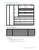
B AL_PA Cross References Arbitrated Loop Physical Addresses AL_PA AL_PA ID AL_PA AL_PA ID AL_PA AL_PA ID (hex) (hex) (decimal) (hex) (hex) (decimal) (hex) (hex) (decimal) EF E8 E4 E2 E1 E0 DC DA D9 D6 D5 D4 D3 D2 D1 CE CD CC CB CA C9 C7 C6 C5 C3 BC BA B9 B6 B5 B4 B3 B2 B1 AE AD AC AB AA A9 A7 A6 A5 00 01 02 03 04 05 06 07 08 09 0A 0B 0C 0D 0E 0F 10 11 12 13 14 15 16 17 18 19 1A 1B 1C 1D 1E 1F 20 21 22 23 24 25 26 27 28 29 2A 0 1 2 3 4 5 6 7 8 9 10 11 12 13 14 15 16 17 18 19 20 21 22 23 24
AL_PA Cross References
Glossary ABTS Abort Basic Link Service. AL_PA or Arbitrated Loop Physical Address A one-byte value used to identify a port in an Arbitrated Loop topology. The value of the AL_PA corresponds to bits 7:0 of the 24-bit Native Address Identifier. CLI Command Line Interface. A command-based interface for configuring, managing, and displaying switch settings. CLS Close Primitive Signal. Sent by a port that is currently communicating on the loop, to close communication to another port.
SES SCSI Enclosure Services. A subset of the SCSI protocol used to monitor temperature, power, and fan status for enclosed devices. SFP Small Form-Factor Pluggable transceiver. These transceivers are fully compliant with FC-PI and MSA standards and occupy less than half the board space of the existing GBIC products. SOC Switch On a Chip SOF Start Of Frame. A group of ordered sets used to mark the beginning of a frame.
Index A AL_PA displaying 26 SES device 11 AL_PA Cross References 39 B beaconing ports 19, 23 C canceling commands 6 changing firmware images 33 password 8 switch password 11 clearing event log 15 Fault LED 15 port counters 23, 26 CLI access 5 initial switch setup 7 overview 5 command 25 commands 9 canceling 6 config/..
D date 8, 13 defaults password 8, 11 switch settings 11 DHCP 7, 20 diagnostics beaconing ports 23 clearing counters 23 displaying port AL_PAs 23 displaying port error counters 23 Diagnostics menu beacon command 23 clrctr command 23 galpa command 23 prtctrs command 23 disabling syslog server 16 disabling ports 19 displaying current menu 10 event messages 25 firmware information 33 network settings 20 port AL_PAs 23, 26 port error counters 23 port insertion counters 25 port speed 25 port utilization 26 sensor
N S name setting 13 navigating menus 6 netmask 7 network configuring gateway setting 21 configuring IP address 21 configuring network mask setting 21 connection 5 displaying settings 20 network configuration 20 Network Configuration menu 20 gateway command 21 ip command 21 mask command 21 reset command 21 show command 20 network mask configuring 21 network settings 7 saving configurations 17 sending a LIP 19 sensor information 27 serial interface connection 5 SES device AL_PA 11 setting DHCP 20 port spee
sev command 14 syslog command 15 time command 13 T terms see glossary 41 threshold settings Fault LED 15 time 8, 13 troubleshooting 19 U using menus 6 46