HP P6300/P6500 EVA M6612/M6625 Disk Enclosure Installation Instructions HP Part Number: 5697-1395 Published: December 2011 Edition: 2
© Copyright 2011 Hewlett-Packard Development Company, L.P.
About this document This document describes how to install an M6612 or M6625 disk enclosure into a rack as part of an P6300/P6500 EVA storage array. The disk enclosure installation may be performed while the array is in operation. You can only add one disk enclosure online at a time. These instructions do not include adding an expansion rack. For expansion rack information, see the HP P6300/P6500 Enterprise Virtual Array Expansion Rack Reference Guide.
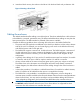
2. Secure rack rails to the front and back rack columns using screws. Make sure that the shoulders of the screws fit inside the square or round holes of the rack (2, Figure 1 (page 4)). NOTE: If installing rails in a square hole rack, use larger-sized shoulder screws and pins for mounting. If installing rails in a round hole rack, use smaller-sized shoulder screws and pins for mounting.
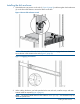
Installing the disk enclosure 1. Slide the device into position on the rails (1, Figure 2 (page 5)) and then tighten the thumbscrews (2) on the front of the device to secure the device to the rack. Figure 2 Secure disk enclosure to rack NOTE: The rear ends of the rails have a CTO bracket that must engage the device chassis to secure the rear of the chassis to the rails (Figure 3 (page 5)). Figure 3 Engaging CTO bracket 2.
Figure 4 Installing tie wraps and routing cables 3. Populate the enclosure with available disk drives (not included with this kit). Start with the lowest number in for the M6625, and Figure 7 (page 6) for the M6612, and continue in order until you have inserted the desired number. If installing multiple disk enclosures, balance the quantity and sizes of disk drives between the enclosures as evenly as possible.
4. Insert drive blank into any slots without a disk drive. Push the drive blank until you detect a click. Figure 8 Inserting a drive blank Cabling the enclosure Two methods are described for cabling a new disk enclosure. The online method allows a disk enclosure to be added to a powered, operational array. The offline method describes cabling an array that has been powered down. The offline method is preferred if downtime is available.
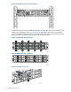
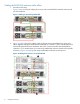
Cabling the P6300 EVA enclosure while offline 1. Power down the array. Figure 9 (page 8) shows the cabling for an array with one P6300 EVA controller enclosure and two disk enclosures. Figure 9 Cabling for preexisting P6300 EVA 2. Figure 10 (page 8) shows the cabling when two disk enclosures are added to the array as an offline upgrade. Unplug the cable between DP-B (Red) on controller 1 and I/O module B port P2 of the existing disk enclosure at the bottom of the rack.
Table 1 Adding disk enclosures to the P6300 EVA callouts 3.
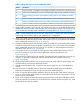
13. Verify the status of the newly installed disk enclosure: a. Open HP P6000 Command View. b. Navigate to the newly added disk enclosure within the Hardware folder in the navigation pane and select it. The Disk Enclosure Properties window opens. c. Select the I/O tab and verify that the Operational state for both ports on both I/O modules is Good. NOTE: If the newly added disk enclosure is at a different I/O module firmware version, the overall operational state will display Loading firmware.
Figure 11 Adding a disk enclosure to the P6300 EVA Table 2 Adding a disk enclosure to the P6300 EVA callouts 4.
d. For the I/O module that you connected, check that the overall operational state and the connection and operational states for each port displays Good. The other I/O module that is not yet connected will display Not installed for the overall operational state and Not available for each port operational state. NOTE: If the newly added disk enclosure is at a different I/O module firmware version, the overall operational state will display Loading firmware.
Cabling the P6500 EVA enclosure while offline Adding below the controller enclosure 1. Power down the array and existing disk enclosures. Figure 12 (page 13) shows the cabling for an array with one P6500 EVA controller enclosure and four disk enclosures. With the P6500 EVA, disk enclosure are balanced as evenly as possible above and below the controller enclosures. Additionally, the controller enclosure and disk enclosures are connected using Y-cables.
Figure 13 Adding a disk enclosure below the P6500 EVA Table 3 Adding a disk enclosure below the P6500 EVA callouts 3. 4. 5.
Adding above the controller enclosure Complete the following procedure to add a disk enclosure above the controller enclosure. 1. Figure 14 (page 15) shows the cabling when a disk enclosure is added above the controller enclosure. Unplug the DP-2 cable from I/O module port P1 of the existing disk enclosure nearest the newly installed disk enclosure and plug it into port P1 of I/O module A of the newly installed disk enclosure (1, Figure 14 (page 15)).
2. 3. 4. Using a cable provided in your kit, plug one end into the P1 port of I/O module A (above the controller enclosure) that was unplugged in the previous step and plug the other end into port P2 of I/O module A of the newly installed disk enclosure (2, Figure 14 (page 15)). Complete the connections to I/O module B of the newly installed disk enclosure (above the controller enclosure).
step) before you connect the other I/O module (in this example, B). Failure to complete this verification could result in potential loss of data access for an extended period of time. Complete the following steps to verify: a. Open HP P6000 Command View. b. Navigate to the newly added disk enclosure within the Hardware folder in the navigation pane and select it. The Disk Enclosure Properties window opens. c. Select the I/O tab. d.