
HP P6300/P6500 EVA M6612/6625 Disk Enclosure Installation Instructions (5697-1395, December 2011)
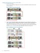
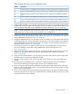
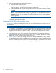


Figure 13 Adding a disk enclosure below the P6500 EVA
Table 3 Adding a disk enclosure below the P6500 EVA callouts
DescriptionCallout
Connects installed I/O module A, port P1 (below controller) to controller 1, port DP-A (using the DP-1
cable)
1
Connects installed I/O module A, port P2 (below controller) to existing I/O module, port P12
Connects installed I/O module B, port P1 (below controller) to controller 2, port DP-B (Red) (using the
DP-1 cable)
3
Connects installed I/O module B, port P2 (below controller) to existing I/O module B, port P14
3. Using a cable provided in your kit, plug one end into the P1 port of I/O module A (below the
controller enclosure) that was unplugged in the previous step and plug the other end into port P2
of I/O module A of the newly installed disk enclosure (2, Figure 13 (page 14)).
4. Complete the connections to I/O module B of the newly installed disk enclosure (below the
controller enclosure). The result is the DP-1 cable on port P1 of I/O module B of the disk enclosure
previously closest to the controller enclosure is moved to port P1 of I/O module B of the newly
installed disk enclosure (3, Figure 13 (page 14)). Also, a new cable is installed between I/O
module B port P1 of the existing disk enclosure and I/O module B port P2 of the newly installed
disk enclosure (4, Figure 13 (page 14)).
5. Follow steps 8–14 in “Cabling the P6300 EVA enclosure while offline” (page 8) to complete
the installation.
14 Cabling the enclosure