
HP StorageWorks Power Supply/Blower Replacement Instructions (5697-5527, January 2006)

Verifying component failure
The power supply and blower are separately replaceable components.
Before replacing a power supply or blower , use the following methods
to verify component failure.
MS A products
• Check the power supply/blower status indicator. See Figure 1.It
should be off.
• On the front o
f the MSA 1000, use the controller display buttons to
scroll throu
gh the messages disp layed on the controller LCD panel
and locate the following message:
409 STORAGE BOX #<n> POWER SUPPLY FAILED
The<n>valueinthemessageidentifies which enclosure has the
failed powe
rsupply.
•Box1-MSAe
nclosure
•Box2-Disk
enclosure attached to Port A of the MSA
•Box3-Disk
enclosure attached to Port B of the MSA
EVA products
CAUTION:
If Command View EVA does not present a status consistent
with that of the power supply/blower status indicator, or if
Command View or the System Event Analyzer indicates multiple
hardware failures, contact HP support for assistance. The HP
support web site is located at h
ttp://www.hp.com/support
• Analy
ze any failure messages you may have received from system
monit
oring (System Event Analyzer).
• Check
status using Command View EVA:
1. In th
e Navigation pane, select Storage system > Hardware >
Rack
>Diskenclosure
2. In t
he Content pane, select the Power tab or the Cooling tab
the
n the appropriate component (1 or 2). The Operational
state should be
Failed .
3. To help identify the correct enclosure, click Locate > Locate On
to flash the status ind icators on the front of the disk enclosure.
• Check the power supply/blower status indicator. See Figure 1.It
should be off.
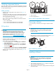
1
0006
b
2 3
1. Status indicator
2. Power supply/blower 1
3. P ower supp
ly/blower 2
Figure 1 Power sup ply/blower status indicator
Removing a blower
It is not necessary to remove the power supply to replace a failed
blower.
WARNING!
The blo wer motor does not stop immediately when the blower
is removed. Keep your fingers away from the blower blades
until the motor stops.
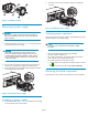
• While pushing in on the two wine-colored mounting tabs (1, Figure
2) , pull t
he blower (2) away from the power supply.
1
1
0007
a
2
Figure 2 Removing a blower
Installing a b lower
CAUTION:
Pressing on the center section of the blower can damage the
blades or the housing. Only press on the outer edge of the
blower when installing it.
1. Align the blower guide post (2, Figure 3) with the mounting hole
next to the p ower supply connector (1).
2. Slide the blower onto the power supply (4) until the mounting tabs
(3) snap into place.
Page 2