
HP StorageWorks controller enclosure cache battery replacement instructions (531236-001, March 2009)

3. To help identify
the correct controller, click Locate > Locate On
to display Locat
e Confirmed on the OCP. The blue Unit
ID indicator wi
ll also turn on.
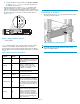
• Check the batte
ry status indicators (Figure 1). The battery fault
indicatorshouldbeon. Ifthereisabatteryfailure,thestatus
indicator will be off and the fault indicator will be on (not flashing).
See Table 1 fo
r descriptions of the battery status indicators. To view
the status in
dicators it is necessary to remove the front bezel as
shown in Figu
re 2.
gl0135
Figure 1 Battery ind icator loca t ions
1
Status indicator
2
Fault indicator
Table 1 describes battery status using the battery indicators. When
abatteryisfirst installed, the fault indicator goes on (solid) for
approximately 30 seconds while the system discovers the new battery.
Then, the battery status indicators display the battery status as described
in Table 1.
Table 1 Battery indicator descriptions
Status
indicator
Fault
indicator
Description
On
Off
Normal operation. A maintenance
charge process keeps the bat ter y
fully charged.
Flashing Off
Battery is undergoing a full
charging process. This is the
indication you typically see after
installing a new battery.
Off
On
Battery fault. The battery has failed
andshouldbereplaced.
Off
Flashing
The battery has experienced an
over temperature fault.
Flashing (fast) Off
Battery code is being updated.
When a new batter y is installed, it
may be necessar y for the controllers
to update the code on the battery to
the correct version. Both indicators
flash rapidly for approximately 30
seconds.
Flashing
Off
Batter y is undergoing a scheduled
battery l oad test, during which the
battery is discharged and then
recharged to ensure it is working
properly. During the discharge
cycle, you will see this display. The
load test occurs infrequently and
takes several hours.
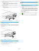
Removing a battery
1. Remove the front bezel (Figure 2) by grasping the bezel at each
end pulling it off the enclosure.
Figure 2 R emoving the front bezel
NOTE:
To provide clarity, the controller enclosure is shown out the
cabinet in subsequent figures.
Page 2