HP EVA6400/8400 M6412A disk enclosure installation instructions HP Part Number: 5697-0974 Published: June 2011 Edition: Third
© Copyright 2009, 2011 Hewlett-Packard Development Company, L.P.
About this document This document describes how to install an M6412A disk enclosure in a rack that is part of an EVA6400/8400 storage array. You can add a disk enclosure to the EVA6400/8400 while the array is online. You can only add one disk enclosure online at a time. These instructions do not include adding an expansion rack. For expansion rack information, see the HP 6400/8400 Enterprise Virtual Array Expansion Rack Reference Guide.
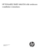
Figure 1 Disk enclosure kit contents 1 Disk enclosure 5 Rails with –03 brackets 2 Eight disk drive blanks (may come pre-installed in enclosure) 6 Two Fibre Channel copper cables 3 –04 brackets (not used) 7 Two enclosure power cords 4 Accessory kit Attaching the rails The rail kit supplied with the disk enclosure comes configured for square-hole racks. IMPORTANT: Do not remove the pins from the ends of the rails unless you are converting the rails for use in round-hole racks.
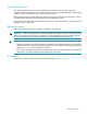
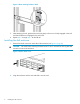
To attach the rails to the rack: NOTE: The designation of left and right rail is made when looking at the front of the rack. The rails are marked by an R (right) and L (left) stamped on the metal. 1. 2. Insert the rear end of the right rail into the inside back of the rack until the pins partially extend through the holes in the rack upright. On the rear of the rail, squeeze the scissors latch (1, Figure 3 (page 5)) to insert the rail and pins though the rack upright holes (2) until the latch engages.
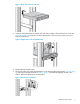
Figure 5 Move retaining bracket to back 5. 6. After attaching the rail, grab and move the rail gently to be sure it is firmly engaged in the rack and that all latches are engaged in the rack holes. Repeat Step 1 through Step 5 for the left rail. Installing the disk enclosure 1. Remove the bezel covers from each side of the enclosure (see Figure 6 (page 6)). CAUTION: Be careful when removing the bezel covers so as to not break the locking tabs that secure the covers to the enclosure.
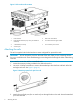
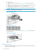
Figure 7 Slide disk enclosure onto rails 3. Continue sliding the enclosure into the rack until the front edge is flush with the front of the rack (1, Figure 8 (page 7)). Tighten the enclosure thumbscrews into the rack (2), taking care not to strip the thumbscrews. Figure 8 Tighten disk enclosure thumbscrews 4. 5. Reattach the front bezel covers.
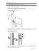
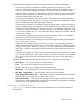
6. To install disk drives: a. Insert the disk drive into the drive bay (1, Figure 10 (page 8)) until it clicks, locking the drive. b. Push firmly on the front of the drive carrier to ensure the drive is fully seated into the enclosure. c. Rotate the drive lever to the right (2, Figure 10 (page 8)) until it locks. d. Ensure the drives are installed in the proper sequence, following the numbering scheme in Figure 11 (page 8).
Consider the following guidelines when connecting disk enclosures to the EVA6400/8400: • One rack may contain two EVA6400 or EVA8400 controllers and a maximum of 18 disk enclosures. The EVA6400 supports a maximum of 18 disk controllers. The EVA8400 supports up to 27 disk enclosures, but adding disk enclosures 19 through 27 requires an expansion rack. • The power cords are supplied in two different colors should you decide to use the colors to denote sides of the rack.
Figure 13 Cabling for an existing EVA6400 2C2D configuration Loop 1 I/O-A I/O-B P1 / P2 P1 / P2 01 02 Shelf-2 Shelf-2 (S-2) (S-2) 03 04 Controller “A” Memory Card UID DP1-A / DP2-A DP1-B / DP2-B Mfg DP1-A DP2-A MP1 FP1 FP2 FP3 FP4 MP2 DP1-B DP2-B PS 1 01 MP1 – MP2 – Jumper Cables 05 PS 2 07 03 Controller “B” Memory Card UID DP1-A / DP2-A DP1-B / DP2-B Mfg DP1-A DP2-A MP1 FP1 FP2 FP3 FP4 MP2 DP1-B DP2-B PS 1 02 PS 2 08 04 06 Loop 2 I/O-A I/O-B P1 / P2
. In HP P6000 Command View, verify that the newly installed disk enclosure appears as part of the array hardware in the navigation pane, and that the I/O modules show a good operational status.
Figure 16 Cabling for an existing EVA8400 2C3D configuration Loop 1 I/O-A I/O-B P1 / P2 P1 / P2 Shelf-3 (S-3) 01 03 02 04 Controller “A” Memory Card UID DP1-A / DP2-A / DP3-A Mfg DP1-A DP2-A DP3-A MP1 FP1 FP2 FP3 FP4 DP1-B / DP2-B / DP3-B MP2 DP1-B DP2-B DP3-B PS 1 05 MP1 – MP2 – Jumper Cables 01 09 07 03 PS 2 11 Controller “B” Memory Card UID DP1-A / DP2-A / DP3-A Mfg DP1-A DP2-A DP3-A MP1 FP1 FP2 FP3 FP4 MP2 DP1-B / DP2-B / DP3-B DP1-B DP2-B DP3-B PS 1 02
9. Power on controller A by pressing the power button on rear of the controller until the controller responds (it may take up to 10 seconds for the controller to power on). Repeat this step for controller B. Wait five minutes for the array to stabilize. 10. Verify that I/O modules A and B on the added disk enclosure have been assigned an index number of the next higher enclosure number. For example, if the previous highest index number was “3,” then the installed enclosure should display “4.” 11.
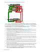
Figure 18 Revised cabling for complete EVA8400 2C4D configuration Loop 1 I/O-A I/O-B P1 / P2 P1 / P2 I/O-A I/O-B P1 / P2 P1 / P2 Shelf-4 (S-4) 04 01 Shelf-3 (S-3) 03 02 Controller “A” Memory Card UID DP1-A / DP2-A / DP3-A Mfg DP1-A DP2-A DP3-A MP1 FP1 FP2 FP3 FP4 DP1-B / DP2-B / DP3-B MP2 DP1-B DP2-B DP3-B PS 1 05 01 MP1 – MP2 – Jumper Cables 09 07 03 PS 2 11 Controller “B” Memory Card UID DP1-A / DP2-A / DP3-A Mfg DP1-A DP2-A DP3-A MP1 FP1 FP2 FP3 FP4 MP2
NOTE: With only one I/O module from the newly added enclosure cabled to the array, there will be HP P6000 Command View warnings that indicate disk drives are only connected on one of the redundant Fibre Channel loops. This is to be expected, and the warnings should clear as soon as the other I/O module is connected. 4.