AB465A PCI-X 2-Port 2 Gigabit Fibre Channel and 2-Port Gigabit Ethernet Combination Card Installation Guide For fcd Driver Versions B.11.11.04 and B11.23.02 and For igelan Driver Versions B.11.11.17 and B.11.23.05 HP 9000 and HP Integrity Systems Manufacturing Part Number : AB465-90001 E0205 U.S.A. © Copyright 2005 Hewlett-Packard Development Company L.P.
Legal Notices The information in this document is subject to change without notice. Hewlett-Packard makes no warranty of any kind with regard to this manual, including, but not limited to, the implied warranties of merchantability and fitness for a particular purpose. Hewlett-Packard shall not be held liable for errors contained herein or direct, indirect, special, incidental or consequential damages in connection with the furnishing, performance, or use of this material.
Hardware and Software Installation Procedure Step 1: Access the system card bay Hardware and Software Installation Procedure These instructions apply to AB465A PCI-X 2-Port 2 Gigabit Fibre Channel and 2-Port Gigabit Ethernet combination cards which can operate on HP-UX 11i v 1.0 of December 2004 or HP-UX 11i v 2.0 of September 2004 or later. If your system is running HP-UX 11i v 1.0, you can find the 11i v 1.0 LAN and fibre channel driver bundles on the December 2004 OE distribution media. For 11i v 1.
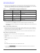
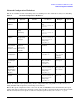
Hardware and Software Installation Procedure Step 4: Connect the fibre channel devices • Attach the free end of the LAN cable to any unused port on the switch. The Base-T connections on the card operate at 10 or 100 Mbit/s in either full- or half-duplex modes and at 1000 Mbit/s only in full-duplex mode. Set the ports on the card and on your switch according to the following table.
Hardware and Software Installation Procedure Step 6: Install the latest software. • Check the Release Notes for GigEther-01 and FibrChanl-01 to see if you need to install any appropriate patches for your system. Release Notes are available on the Web at http://docs.hp.com under Networking and Communications. Step 6: Install the latest software. • Load the software media into the appropriate drive. If you are adding the Gigabit Ethernet software bundle (GigEther-01) for HP-UX 11i v 1.
Hardware and Software Installation Procedure Step 8: Verify the fibre channel installation Step 8: Verify the fibre channel installation • To verify that the fc driver appears for each installed card, enter: ioscan -fk The ioscan output might look like the following: Class I H/W Path Driver S/W State H/W Type Description fc 4 1/0/8/1/0/4/0 fcd CLAIMED INTERFACE HP AB465-60001 PCI/PCI-X 2-port 2Gb FC/2-port 1000B-T Combo Adapter (FC Port 1) fc 5 1/0/8/1/0/4/1 fcd CLAIMED INTERFACE HP AB465-60001 PCI/PCI-
Hardware and Software Installation Procedure Optional Step: Configure Jumbo Frames Size (Jumbo frames are supported only at 1000 Mbit/s) • Installation is complete when you have successfully run linkloop, ping and netstat. To configure remote systems, see the Ethernet Support Guide available on the web at http://docs.hp.com. Do this step only if remote systems have not been previously configured.
Hardware and Software Installation Procedure For Further Information An alternative way to temporarily configure jumbo frame size is to enter: lanadmin -M mtu_size PPA_number. Using lanadmin is temporary because it will not preserve your settings across reboots. The PPA_number is the one we obtained from the output of lanscan. For using Jumbo Frames with the igelan Gigabit Ethernet driver on HP-UX 11i v 1.0, set the mtu_size to 9000 (bytes). For using Jumbo Frames with the igelan driver on 11i v 2.
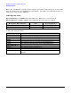
Hardware and Software Installation Procedure Network Configuration Worksheet Network Configuration Worksheet Fill out one worksheet for the networking data of each LAN port on the combination card you are installing. Table 2 Data Type Network Configuration Worksheet Required/ Optional Default How to Configure (see Note 1) Example Internet Address Required 0.0.0.0 SAM or ifconfig or edit /etc/rc.config.d/ netconf 196.6.20.
Hardware and Software Installation Procedure Cable Specifications Note 3: The valid MTU size for normal frames using the igelan driver on HP-UX 11i v 1.0 or v 2.0 is 1500 bytes. For Jumbo Frames, the valid MTU size on HP-UX 11i v 1.0 is 9000 , and for HP-UX 11i v 2.0, it is a number in the range of 1501 to 9000 bytes.
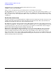
Hardware and Software Installation Procedure Figure 1 AB465A PCI-X 2-Port 2Gb FC/ 2-Port 1000B-T Combination Card Port 1 Speed LEDS (Port 1) Fibre Channel Connectors (Duplex LC) Speed LEDS (Port 2) 1Gb 2Gb 2Gb 1Gb Port 2 LAN B } Activity/Link LEDs Flashing = Data traffic Solid = Active link OFF = No link 1000Base-T Connectors (RJ-45) LAN A PCI-X 133 MHz Speed LEDs Off = 10 Mbit/s Green = 100 Mbit/s Yellow = 1000 Mbit/s 11
Hardware and Software Installation Procedure Features Features The AB465A PCI-X Combination cards have the following features: • PCI-X 133 MHz capable card. It can operate at 32-bit or 64-bit compatible modes and is supported in the following frequencies: PCI 66, PCI-X 66, and PCI-X 133. Best performance is achieved by putting the card in a “dual-rope” PCI-X 133 slot. To identify which slots are the dual rope slots in a particular system, please refer to the hardware users’ guide for each system.
Hardware and Software Installation Procedure Interoperability: Supported Systems Interoperability: Supported Systems Supported Systems The combination card is supported in the HP Integrity (Itanium or Itanium2-based) systems specified in Table 3. Table 3 Combination Card in HP Integrity Systems rx1600, rx1620 ; These servers accommodate 1 AB465A per system.
Card Physical and Environmental Specs and Regulatory Information Card Physical and Environmental Specifications Card Physical and Environmental Specs and Regulatory Information Card Physical and Environmental Specifications Following are the product physical and environmental specifications of the AB465A PCI-X 2-Port 2 Gigabit Fibre Channel and 2-Port Gigabit Ethernet Combination Card. Physical Specifications Form Factor PCI-X (rev 2.3) full-height card PCI support 64-bit 3.3V only 133Mhz Height 10.
Card Physical and Environmental Specs and Regulatory Information Card Physical and Environmental Specifications Operating Altitude 3,000 meters (9900) ft Non-operating Altitude 4,500 meters (14850 ft) Electromagnetic Compatibility This document contains regulatory statements for the United States and the European community.
Card Physical and Environmental Specs and Regulatory Information FCC Statement (For U.S.A.) FCC Statement (For U.S.A.) Federal Communications Commission Radio Frequency Interference Statement WARNING This device complies with Part 15 of the FCC rules. Operation is subject to the following two conditions: (1) This device may not cause harmful interference and (2) this device must accept any interference received, including interference that might cause undesired operation.
Card Physical and Environmental Specs and Regulatory Information Laser Safety Statements Laser Safety Statements Laser Safety Statements - U.S. FDA/CDRH - Optical (laser) Transceiver CAUTION The optical transceiver provided on the network interface card contains a laser system and is classified as a “Class-I Laser Product” under a U.S. Department of Health and Human Services (DHHS) Radiation Performance standard according to the Radiation Control for Health and Safety Act of 1968.
Card Physical and Environmental Specs and Regulatory Information Laser Safety Statements 18