HP PCIe 8Gb 1 port and 2 port Fibre Channel Emulex HBAs using Windows and HP-UX Installation Guide HP Part Number: AH402-9001A_ed2 Published: April 2009 Edition: 2
© Copyright 2009 Hewlett-Packard Development Company, L.P.© Copyright 2008 Emulex Corporation. Hewlett-Packard Company makes no warranty of any kind with regard to this material, including, but not limited to, the implied warranties of merchantability and fitness for a particular purpose. Hewlett-Packard shall not be liable for errors contained herein or for incidental or consequential damages in connection with the furnishing, performance, or use of this material.
Table of Contents About this guide.................................................................................................................9 Intended audience..................................................................................................................................9 Related Windows documentation..........................................................................................................9 Document conventions and symbols.............................................
Laser product label...............................................................................................................................31 International notices and statements....................................................................................................31 Canadian notice (avis Canadien)..........................................................................................................31 Class A equipment...................................................................
List of Figures 4-1 4-2 6-1 6-2 6-3 6-4 Single and dual channel HBAs......................................................................................................20 LED location..................................................................................................................................20 Class 1 laser product label.............................................................................................................31 BSMI notice...........................................
List of Tables 1 2 1-1 1-2 1-3 4-1 5-1 5-2 5-3 6 HP Model numbers and Product numbers for 8 Gb HBAs............................................................9 Document conventions....................................................................................................................9 Environmental specifications........................................................................................................13 Physical Specifications.....................................................
List of Examples 5-1 5-2 Hardware Path for a Direct Fabric Attach Device.........................................................................28 Hardware Path for a Private Loop Device....................................................................................
About this guide This guide provides information about installing, configuring, and troubleshooting the following single and dual channel host bus adapters. Table 1 HP Model numbers and Product numbers for 8 Gb HBAs HP Model Number HP Product Number Description 81e AH402A 8Gb PCI-e single channel HBA 82e AH403A 8Gb PCI-e dual channel HBA Intended audience This guide is intended for technical support personnel.
WARNING! Indicates that failure to follow directions could result in bodily harm or death. CAUTION: data. Indicates that failure to follow directions could result in damage to equipment or IMPORTANT: NOTE: TIP: Provides clarifying information or specific instructions. Provides additional information. Provides helpful hints and shortcuts. Subscribers choice HP strongly recommends that customers sign up online using the Subscriber's choice website: http://www.hp.com/go/e-updates.
• • http://www.hp.com/support/ http://www.docs.hp.
1 HBA specifications This chapter contains the HBA specifications, including: • • • Environmental specifications Physical specifications HBA media specifications Environmental specifications Table 1-1 “Environmental specifications” lists the HBAs environmental specifications.
HBA media specifications Use multimode fiber optic cable, with short-wave lasers, that adheres to the specifications listed in Table 1-3 “Media specifications”. Table 1-3 Media specifications Fiber Optic cable 14 Maximum length Minimum length Connector 62.5/125 μm (multimode)200 MHz/km bandwidth • • • • 300 meters at 1.0625 Gb/s 150 meters at 2.125 Gb/s 70 meters at 4.25 Gb/s 21 meters at 8.5Gb/s 0.5 meters LC 50/125 μm (multimode)500 MHz/km bandwidth cable • • • • 500 meters at 1.
2 Installing HBAs This chapter describes the following topics for installing HBAs: • • Installation prerequisites Installing the HBA See your server's documentation for additional information about installing HBAs. WARNING! Disconnect the host from the power source before installing HBAs. To reduce the risk of personal injury from hot surfaces, allow the internal server or workstation components to cool before touching. CAUTION: Electrostatic discharge (ESD) can damage electronic components.
Installing the HBA Use the following procedure for installing the HBA into a computer. CAUTION: Be sure to observe the ESD precautions for this procedure as described in Regulatory compliance and safety. 1. 2. 3. Make sure the computer is powered off. Remove the screws on the computer cover, and then remove the cover. Wearing an anti-static wrist strap, remove the blank panel from an empty x4, x8, or x16 PCIe bus slot. NOTE: The HBA comes with a standard PCI bracket installed.
3 Installing the Windows Smart Component driver kit This chapter describes how to locate and download the Windows Smart Component driver kit from the web. This chapter also describes how to install or update your Windows driver.
4 Troubleshooting Under the Windows Environment This chapter contains information to help resolve HBA problems that might occur. The chapter contains the following sections: • • • HBA LEDs POST LED states Using the Event Viewer Setting the jumpers HBA LEDs POST LED states Table 4-1 “POST LED states” lists the HBA LED states and describes the meaning of each state. If the LEDs indicate a failure during POST: 1. 2. 3. Make sure the HBA is seated firmly in the PCI slot.
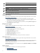
HBA LEDs Figure 4-1 Single and dual channel HBAs Figure 4-2 “LED location” shows the LEDs that are referenced in this document. Figure 4-2 LED location See Table 4-1 (page 19) for a description of the LEDs. Using the Event viewer The miniport drivers verify the condition of the HBA's POST LED states. If there is a failure or a suspected failure, an error log entry is issued to the Windows event log. Viewing the Event log Use the following procedure to view the Event log. 1. 2.
3. 4. In the pop-up window, select a folder for extracting the files, and then click OK. Review the error code in formation from the relevant file. NOTE: The Emulex Storport miniport driver records error events in the Windows System Event log. The Stopport and SCSIPORT minidirvers documentation describes the event log format and how to interpret the information in the log. Use the documentation specific to the miniport driver that you are running.
5 Fibre Channel Adapter Installation on HP-UX Systems This chapter contains installation prerequisites, guidelines, and procedures for each host bus adapter.
See the HP-UX Fibre Channel (fcd and fclp) Host Bus Adapter Support Matrix at http://docs.hp.com/ en/netcom.html#Fibre%20Channel for the most current information on supported products. To install the software bundle, follow these steps: 1. 2. 3. Log in to the system as root. Insert the CD or DVD into the drive. Mount the CD using the following command: mount /dev/dsk/ / 4. Run swinstall to install the software.
NOTE: HP-UX 11i v3 does NOT support Online Deletion (OLD) with fclp. NOTE: HP-UX 11i v2 supports Online Addition (OLA) ONLY with fclp. It does NOT support Online Replacement (OLR) or Online Deletion (OLD). Confirm whether OL* is supported on the system in which you plan to install a Fibre Channel adapter. See the HP Fibre Channel Host Bus Adapter Support Matrix, at: http://docs.hp.com/en/ netcom.
Attaching the Adapter to Other Fibre Channel Devices To attach the adapter to other Fibre Channel devices, follow these steps: 1. 2. Remove the Fibre Channel host bus adapter’s optical port protector (if included). Attach a connector cable to the Fibre Channel host bus adapter. a. Align the slotted plug with the keyed connector. b. Push the connector in until you hear it click. 3. 4. Attach the free end of the cable to a compatible Fibre Channel device.
/dev/dsk/c138t3d0 /dev/rdsk/c138t3d0 NOTE: The third column represents the hardware path of the slot in which the adapter is installed. The hardware path is different for each installed adapter. If an installed Fibre Channel adapter requires the fclp driver and the appropriate driver does not appear as shown above, the driver is not installed. If the ioscan output is similar to the following: fc 0/0/2/1/0 UNCLAIMED UNKNOWN HP-UX detected the adapter, but the drivers are not properly loaded.
Interpreting Hardware Paths Examples 2-1 and 2-2 illustrate the Fibre Channel hardware path format: Example 5-1 Hardware Path for a Direct Fabric Attach Device Adapter Domain Area Port Bus Target LUN 0/1/2/0.1.19.255.0.0.0 Example 5-2 Hardware Path for a Private Loop Device Adapter Domain Area Port Bus Target LUN 0/1/2/0.8.0.255.0.1.0 Table 5-3 describes each field in the hardware path.
Table 5-3 Hardware Path Field Descriptions (continued) Fibre Channel Topology of HBA Field Target Value Depends on the Fibre Channel topology and the LUN addressing method used. Fabric Topologies Private Loop For LUNs with Peripheral Device Addressing, the value of this field is the lower 4-bits of the third byte of the N_Port ID of the target device. This field usually corresponds to the Arbitrated Loop Physical Address (AL_PA) of the target device.
6 Regulatory compliance and safety Laser device All HP systems equipped with a laser device comply with safety standards, including International Electrotechnical Commission (IEC) 825. With specific regard to the laser, the equipment complies with laser product performance standards set by government agencies as a Class 1 laser product. The product does not emit hazardous light.
European Union notice Products bearing the CE marking comply with the EMC Directive (89/336/EEC) and the Low Voltage Directive (73/23/EEC) issued by the Commission of the European Community and if this product has telecommunication functionality, the R&TTE Directive (1999/5/EC).
Korean notices Figure 6-4 Korean notices Electrostatic discharge To prevent damage to the system, be aware of the precautions you need to follow when setting up the system or handling parts. A discharge of static electricity from a finger or other conductor may damage system boards or other static-sensitive devices. This type of damage may reduce the life expectancy of the device.
Index A audience, 9 B BSMI, regulatory compliance notice, 32 C cable products, 26 cabling requirements, 23 certification and classification information, laser, 31 Class A equipment, Canadian compliance statement, 31 customer replaceable units (CRUs), 23 D driver kit, 17 drivers installing with Smart Component, 17 lpfc, 17 E electrostatic damage prevention, 33 environmental specifications, 13 ESD (electrostatic discharge), 33 precautions, 33 European Union, regulatory compliancex09 notice, 32 Event viewe
using POST LED results, 19 Windows Event viewer, 20 V verifying connectivity, 27 W warnings, lasers, radiation, 31 websites HP documentation, 9 HP Subscriber's choice, 10 Windows driver installation, 17 Event viewer, 20 Windows miniport event log codes, 20 Windows server update prerequisites, 17 Windows Smart Component, 17 downloading, 17 36 Index