HP FlexFabric 11900 Switch Series Installation Guide Abstract This document guides you through installation of HP products, including installing the device, connecting to the network, hardware management, and troubleshooting.
Legal and notice information © Copyright 2013 Hewlett-Packard Development Company, L.P. No part of this documentation may be reproduced or transmitted in any form or by any means without prior written consent of Hewlett-Packard Development Company, L.P. The information contained herein is subject to change without notice.
Contents Preparing for installation ············································································································································· 1 Safety recommendations ·················································································································································· 1 General safety recommendations ··························································································································· 1 Ele
Planning IRF topology and connections ·············································································································· 32 Identifying physical IRF ports on the member switches ····················································································· 32 Installing IRF member switches ····································································································································· 32 Configuring basic IRF settings···················
Module power consumption and system power consumption ·················································································· 62 Card power consumption ····································································································································· 62 Fan tray power consumption ································································································································ 63 System power consumption ····························
Index ··········································································································································································· 97 iv
Preparing for installation The HP FlexFabric 11900 Switch Series includes only the 11908-V model. Table 1 HP FlexFabric 11900 Switch Series models Product code HP description RMN JG608A HP FlexFabric 11908-V Switch Chassis BJNGA-AC0003 IMPORTANT: For regulatory identification purposes, HP FlexFabric 11900 switches are assigned regulatory model numbers (RMN).
Handling safety CAUTION: Do not hold the handle of the fan tray, power supply, or back cover of the chassis, or the air vents of chassis. Any attempt to move the switch with these parts might cause equipment damage and even bodily injury. When you move the switch, follow these guidelines: • Remove all external cables, including the power cords, before moving the chassis. • Moving the chassis requires at least two persons, and you can use a mechanical lift as needed.
Temperature CAUTION: To avoid short circuits, if condensation appears on the chassis when you move it to a high-temperature environment, dry the chassis before powering it on. To ensure normal operation of the switch, make sure the room temperature meets the requirements in Table 2.
Table 5 Harmful gas limits in an equipment room Gas Max. (mg/m3) SO2 0.2 H2S 0.006 NH3 0.05 Cl2 0.01 EMI All EMI sources, from outside or inside of the switch and application system, adversely affect the switch in a conduction pattern of capacitance coupling, inductance coupling, electromagnetic wave radiation, or common impedance (including the grounding system) coupling. To prevent EMI, take the following actions: • Take measures against interference from the power grid.
• Leave at least 10 cm (3.94 in) of clearance at the inlet and outlet air vents. • The rack for the switch has a good cooling system. • The installation site has a good cooling system. • Verify that the airflow design of the chassis meets the airflow design of the installation site.
Installing the switch IMPORTANT: Keep the packages of the switch and the components for future use. Confirming installation preparations Before you install the switch, verify that: • You have read "Preparing for installation" carefully and the installation site meets all the requirements. • If you are rack-mounting the switch, verify that the following conditions are met: { A 19-inch rack is ready for use. For how to install a rack, see the rack installation guide.
• To ensure rack stability, install the slide rails to the lowest possible position when installing a single switch on the rack. To install multiple switches on the rack, mount the heaviest switch at the bottom of the rack. • Identify the chassis and slide rail positions for the switch. For the height and other specifications, see "Appendix A Chassis views and technical specifications." Slide rail installation varies with rack type.
NOTE: One rack unit has three holes, the middle of which is an auxiliary installation hole, and the other two are standard installation holes. You can distinguish them by the space between each two holes. The space between a standard installation hole and an auxiliary installation hole is wider than that between two adjacent standard installation holes. Figure 3 Locating the rack position for installing slide rails (1) Middle of the narrower metal area between holes 3.
Figure 5 Attaching the slide rail to the cage nuts with screws 5. Keep the slide rail horizontally and adjust its length until the installation holes on the rear end of the slide rail touch the cage nuts on the rear rack post. Then screw in screws and fasten. TIP: Install a screw in each mounting hole of the slide rail to ensure its weight bearing capacity. 6. Repeat steps 4 and 5 to install the other slide rail.
Figure 6 Installed slide rails Installing cage nuts To install cage nuts to the front square-holed brackets of the rack: 1. Determine the placement of the cage nuts, depending on holes in the mounting brackets and the mounting position of the slide rails, as shown in Figure 7. 2. Install cage nuts on the square holes on each rack post, as shown in Figure 4.
Figure 7 Installing cage nuts 2 1 (1) Place the bottom edge of the mounting bracket and the slide rail at the same level (2) Locate the installation positions of cage nuts Installing mounting brackets and cable management brackets Before installing the switch to the rack, install the cable management brackets and mounting brackets shipped with the switch.
Installing cable management brackets The 11908-V has two cable management brackets: the cable management brackets are installed at the upper part of the switch, and the power cable management brackets are installed at the lower part of the switch. They are installed in the same way. For more information, see Figure 8. To install a cable management bracket: 1. Unpack the cable management brackets. 2.
Figure 9 Installing the mounting brackets to a 11908-V 2 2 1 3 1 3 (1) Screws for attaching the mounting brackets to the chassis (2) Mounting brackets (3) Fasten the screws Mounting the switch to the rack CAUTION: • Do not hold the handle of the fan tray, power supply, or the back cover of the chassis, or the air vents of chassis. Any attempt to carry the switch with these parts may cause equipment damage or even bodily injury.
HP recommends using a mechanical lift for moving your switch. 3. Place the switch on the slide rails and slide the switch along the slide rails until the mounting brackets on the switch touch the front rack posts, as shown in callout 1 on Figure 10. 4. Attach the chassis to the rack with mounting screws.
IMPORTANT: Before you hammer the shank to the workbench or floor, insert the spade-shaped wedges into the grooves on the shank. Otherwise, the wall anchor cannot be installed correctly. Figure 11 Installing the shank to the plug 1 2 3 4 (1) Shank (2) Groove (3) Plug (4) Spade-shaped wedge Installation procedures CAUTION: Do not use the fan tray handles, power supply handles, chassis air vents, or handle of chassis back cover for moving the chassis. These parts are not designed for weight support.
Figure 12 Attaching L-shaped brackets with wall anchors (1) Fastening screw (2) L-shaped bracket (3) Wall anchor Grounding the switch CAUTION: Before using the switch, connect the grounding cable changely to guarantee lightning protection and anti-interference of the switch. Grounding the switch with a grounding strip CAUTION: • Use the supplied grounding cable (yellow-green grounding cable). • Connect the grounding cable to the earthing system in the equipment room.
2. Remove the grounding screws from the grounding holes at the rear of the chassis, as shown in callout 1 on Figure 13. 3. Fasten the grounding screws, which are attached with the dual-hole terminals of the grounding cable, into the grounding holes of the chassis. 4. Connect the ring terminal of the grounding cable to the grounding post of the grounding strip, and fasten the grounding cable to the grounding strip with the hex nut.
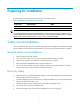
Figure 14 Grounding the switch through the PE wire of the AC power supply Grounding the switch through the RTN wire of a DC power supply CAUTION: Make sure the RTN wire is well grounded from the DC egress of the DC power cabinet. If the switch is powered by a –48 VDC power supply and no grounding strip is available at the installation site, you can ground the switch through the return (RTN) wire of the DC power supply, as shown in Figure 15.
Figure 15 Grounding the switch through the RTN wire of the DC power supply DC power box -48V strip RTN strip PGND strip Ground 19
Installing FRUs There is no required order for installing FRUs. HP recommends that you connect power cords after installing all required FRUs. TIP: Keep the chassis and component packages for future use. Attaching an ESD wrist strap The switch provides an ESD wrist strap. To minimize ESD damage to electronic components, wear the ESD wrist strap and make sure it is well grounded when installing modules. To use an ESD wrist strap: 1. Make sure the switch is well grounded.
Figure 16 Attaching an ESD-prevent wrist strap (on a 11908-V) (1) ESD wrist strap port (having an ESD sign) Installing a card Unless otherwise stated, MPUs, LPUs, and switching fabric modules are collectively referred to as "cards" in this document. All cards of the HP FlexFabric 11900 switches are hot swappable. After all cards are installed, you can verify the running status of a card by referring to the card status LED (SLOT) on the MPU of the switch.
Installing an MPU/LPU The pink edged MPU slots and purple edged LPU slots of a 11908-V switch are located at the front panel. The MPUs and LPUs are vertically oriented. When installing an MPU or LPU, make sure its PCB faces left. To install an MPU or LPU: 1. Wear an ESD wrist strap, and make sure it makes good skin contact and is well grounded. For more information, see "Attaching an ESD wrist strap." 2. As shown in callout 1 on Figure 17, remove the blank filler panel from the slot.
2. Remove the filler panel (if any) from the target slot. Keep the filler panel for future use. See callout 1 on Figure 17. 3. Loosen the captive screws on the protection box on the switching fabric module for the 11908-V switch, hold the ejector levers on the switching fabric module, pressing the buttons on the levers, pull the ejector levers outward, and pull out the module. See Figure 18. Keep the protection box for future use. 4.
Figure 19 Installing the switching fabric module (1) Insert the card into the slot until the brakes touch the slot edges tightly (2) Press the ejector levers inward (3) Fasten the captive screws on the switching fabric module Installing a power supply CAUTION: • Provide a circuit breaker for each power supply and make sure the circuit breaker is off before installation. • Do not install power supplies of different models on the same switch.
AC and DC power supplies are installed in the same way. This section uses an AC power supply as an example. For information about AC and DC power supplies, see HP FlexFabric 11900 2500W AC Power Supply User Guide and HP FlexFabric 11900 2400W DC Power Supply User Guide. Some power supply slots do not have blank panels. The figures in this section are for illustration only. To install the power supply: 1. Wear an ESD wrist strap and make sure it makes good skin contact and is well grounded.
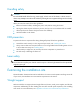
Figure 21 Installing an AC power supply 1 2 (1) Install the power supply to the chassis. (2) Fasten the captive screw. Connecting the power cable Connecting an AC power cable WARNING! Before connecting the power cable, make sure the circuit breaker on the power cable is switched off. To connect an AC power cable: 1. Plug the power cable into the power receptacle of the power supply. 2. Use a cable tie to secure the power cable to the cable management bracket.
3. Plug the other end of the power cable to the AC power receptacle of the power source and switch on the circuit breaker. 4. Verify the power supply input status LED. If the LED is on, the power cable is correctly connected. For description of power supply status LEDs, see "Appendix C LEDs." Figure 22 Securing the power cable Connecting a DC power cable WARNING! • Make sure each power cable has a separate circuit breaker.
Figure 23 Connecting the power cable (1) Insert the power cable plug into the power supply. (2) Fasten the screw. 3. (Optional.) Use a cable tie to secure the power cable to the cable management bracket. For more information, see Figure 22. 4. Connect one end of the blue DC power cable marked with –48V to the negative terminal (–48V) on the power source and the RTN end of the black DC power cable to the positive terminal (RTN).
4. Connect the fiber to the module. For the installation procedure, "Connecting your switch to the network." Figure 24 Installing an SFP+/SFP/QSFP+ module Connecting an SFP+/QSFP+/QSFP+ to SFP+ cable Use SFP+ cables to connect SFP+ ports, QSFP+ cables to connect QSFP+ ports, and QSFP+ to SFP+ cables to connect QSFP+ and SFP+ ports. All these cables are hot swappable. To connect an SFP+, QSFP+, or QSFP+ to SFP+ cable: 1.
Setting up an IRF fabric You can use HP IRF technology to connect and virtualize the switches into a large virtual switch called an "IRF fabric" for flattened network topology, high availability, scalability, and manageability. For more information about IRF, see HP FlexFabric 11900 Switch Series IRF Configuration Guide. IRF fabric setup flowchart The setup flow is shown in Figure 25.
Step Description Plan the installation site and IRF fabric setup parameters: 1. Plan IRF fabric setup. • • • • Planning IRF fabric size and the installation site Identifying the master switch and planning IRF member IDs Planning IRF topology and connections Identifying physical IRF ports on the member switches 2. Install IRF member switches. See "Installing the switch." 3. Power on the switches. N/A 4. Configure basic IRF settings on each switch in standalone mode.
An IRF fabric has only one master switch. You configure and manage all member switches in the IRF fabric at the CLI of the master. IRF member switches will automatically elect a master. You can affect the election result by assigning a high member priority to the intended master switch. For more information about master election, see HP FlexFabric 11900 Switch Series IRF Configuration Guide. Prepare an IRF member ID assignment scheme.
• First configure the member IDs, member priorities, and IRF port bindings for the IRF member switches, save the configuration, connect the member switches, and change the operating mode of the switches to IRF mode. • Assign the master switch higher member priority than any other switch. • Bind physical ports to IRF-port 1 on one switch and to IRF-port 2 on the other switch. • Execute the display irf configuration command to verify the basic IRF settings.
Verifying the IRF fabric configuration After you finish configuring basic IRF settings and connecting IRF ports, verify the basic functionality of the IRF fabric, as follows: 1. Log in to the IRF fabric through the console port of any member switch. 2. Create a Layer 3 interface, assign it an IP address, and make sure the IRF fabric and the remote network management station can reach each other. 3. Use Telnet or SNMP to access the IRF fabric from the network management station.
Connecting your switch to the network This chapter describes how to connect your switch to a network. The first time you access the switch you must log in through the console port. On the switch, you can configure Telnet or SSH for remote access through Ethernet ports. You manage console login users at AUX user lines, and manage Telnet and SSH users at VTY user lines. For more information about login methods and user lines, see HP FlexFabric 11900 Switch Series Fundamentals Configuration Guide.
Figure 27 Connecting a console port to a terminal Setting terminal parameters To configure and manage the switch, you must run a terminal emulator program on the console terminal. If your PC runs Windows 2003 Server, add the HyperTerminal component before performing the following steps to log in to and manage the switch.
Figure 28 Connection description 3. Select the serial port to be used from the Connect using list, and click OK. Figure 29 Setting the serial port used by the HyperTerminal connection 4. Set Bits per second to 9600, Data bits to 8, Parity to None, Stop bits to 1, and Flow control to None, and click OK.
Figure 30 Setting the serial port parameters 5. Select File > Properties in the HyperTerminal window. Figure 31 HyperTerminal window 6. On the Settings tab, set the emulation to VT100 and click OK.
Figure 32 Setting terminal emulation in Switch Properties dialog box Powering on the switch Before powering on the switch, confirm the following: • You know where the emergency power-off switch for the equipment room is located. • The switch has been securely mounted. • All the cards have been correctly installed. • The unused slots have been installed with blank filler panels. • All the network cables, fibers, power cables, and grounding cables have been correctly connected.
The Extended BootWare is self-decompressing......Done. **************************************************************************** * * * BootWare, Version 1.08 * * * **************************************************************************** Compiled Date : Jan 7 2013 CPU Type : XLP316 CPU Clock Speed : 1200MHz Memory Type : DDR3 SDRAM Memory Size : 8192MB Memory Speed : 667MHz BootWare Size : 1536KB Flash Size : 500MB BASIC CPLD Version : 1.0 EXTENDED CPLD Version: 1.
• The system status LEDs on the MPUs show that the system is operating correctly. For more information about LED behaviors, see "Appendix C LEDs." Configuring the switch By default, the switch does not authenticate the console login user at an AUX interface. To increase system security and enable remote management: • Configure remote access services, for example, Telnet or SSH. • Configure authentication on each user interface, including the AUX interfaces.
Configuration example Configuring Telnet service # Enter system view. system-view # Enable the Telnet server. [Sysname] telnet server enable # Enter the view of user line VTY 0. [Sysname] user-interface vty 0 # Enable password authentication on the user line. [Sysname-ui-vty0] authentication-mode password # Set the password to hello in plaintext. [Sysname-ui-vty0] set authentication password simple hello # Assign user role network-admin through the user line VTY 0.
[Sysname-mst-region] quit # Configure the switch as the primary root bridge of instance 1. [Sysname] stp instance 1 root primary # Enable MSTP globally. [Sysname] stp global enable For more information about these features, see HP FlexFabric 11900 Switch Series Configuration Guides. Verifying the network configuration To verify the software version and network configuration, execute display commands in any view. Task Command Display the name, model, and system software version of the switch.
Connecting your switch to the network through optical fibers WARNING! To avoid injury to your eyes, do not stare at the optical fiber interfaces and optical fiber connectors when connecting optical fibers. You can install a transceiver module (see "Installing FRUs") in a fiber port and use optical fibers to connect the port to the network. For more information about optical fibers, see "Appendix D Cables." To connect a fiber port to a peer device through optical fibers: 1.
Testing connectivity After you plug the switch into the network, use the ping or tracert command to test the network connectivity. For more information about these commands, see HP FlexFabric 11900 Switch Series Command References.
Troubleshooting This chapter describes how to troubleshoot your switch. TIP: • Clean your switch periodically because the noncompliant operating environments of switches may cause switch failures. • Verify the installation environments against the requirements in "Preparing for installation." Make sure the switch operates in a compliant environment. • Periodically perform the power-on test for the spare switches.
Garbled terminal display If terminal display is garbled, verify that the following settings are configured for the terminal, for example, HyperTerminal: • Baud rate—9,600 • Data bits—8 • Parity—none • Stop bits—1 • Flow control—none When you modify the settings for the console port of the switch, configure the same settings for the console terminal.
7. Plug a new power supply of the same model into the same slot, and connect it to the same power input end. If the new power supply can operate correctly, the old power supply has failed. You must replace the old power supply. Fan failure Both the MPU and the fan tray provide the fan tray LEDs, including an OK LED and a FAIL LED. When the fan tray operates correctly, the OK LED is on, and the FAIL LED is off. If the OK LED is off or the FAIL LED is on, the fan tray has failed.
3. Calculate the total power consumption, and make sure your power supplies can provide enough power. For more information, see "Appendix B FRUs and compatibility matrixes." 4. Verify that the card is fully seated. You can unplug the card, plug it again, and press the ejector levers inward until the ejector levers touch the panel tightly. For a switching fabric module, you must verify that the ejector levers touch the panel tightly and the switching fabric module seats into the backplane. 5.
Replacement procedures CAUTION: When replacing FRUs while the switch is running, be aware of electrical safety hazards. The switch uses a modular, hot-swappable architecture, and supports FRUs. You can replace any of FRUs when the switch is running. Replacing a power supply WARNING! • Follow the procedures shown in Figure 35 and Figure 36 to replace a power supply to avoid device or bodily injury.
6. Holding the power supply handle with one hand and, supporting the bottom of the power supply with the other, gently pull the power supply out, as shown in callout 2 on Figure 37. 7. Put the removed power supply on the antistatic mat. 8. Install a new power supply. For the installation procedures, see "Installing FRUs.
1. Prepare an antistatic mat to place the removed card. 2. Wear an ESD wrist strap and make sure it makes good skin contact and is well grounded. For more information, see "Installing FRUs." 3. Remove all cables from the card. 4. Use a Phillips screwdriver to remove the captive screw on the card, as shown in callout 1 on Figure 38. 5. Move the ejector levers outwards to separate the card from the backplane, as shown in callout 2 on Figure 38. 6. Use one hand to slowly move the card outwards.
6. Put the removed switching fabric module on the antistatic mat. 7. Install a new switching fabric module. For the installation procedures, see "Installing FRUs.
Figure 40 Replacing a switching fabric module (2) Replacing a fan tray CAUTION: To avoid bodily injury, do not touch the rotating fans when replacing the fan tray. When the fan tray fails, replace the fan tray to ensure normal operation of the switch. The fan tray slot is horizontally oriented for the 11908-V switch. This section describes removing and installing a fan tray on a 11908-V.
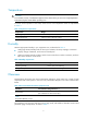
4. Hold the handle of the fan tray with one hand to gently pull the fan tray part way out of the chassis. After the fans stop rotating, support the bottom of the fan tray with the other hand, and take out the fan tray from the chassis, as shown in callout 2 on Figure 41. 5. Put the removed fan tray on the antistatic mat. Figure 41 Removing a fan tray 2 1 1 (1) Loosen the captive screws on the fan tray. (2) Take the fan tray out of the chassis. Installing a fan tray 1.
Replacing a transceiver module WARNING! When you install or remove a transceiver module: • Do not stare at the fibers to avoid hurting your eyes. • Do not touch the golden fingers on the module. Make sure the optical transceiver modules at the two ends of an optical fiber are the same model. Replacing an SFP+/SFP/QSFP+ module 1. Wear an ESD wrist strap and make sure it makes good skin contact and is well grounded. For more information, see "Installing FRUs." 2. Remove the optical fibers on the module.
Support and other resources Contacting HP For worldwide technical support information, see the HP support website: http://www.hp.
Conventions This section describes the conventions used in this documentation set. Command conventions Convention Description Boldface Bold text represents commands and keywords that you enter literally as shown. Italic Italic text represents arguments that you replace with actual values. [] Square brackets enclose syntax choices (keywords or arguments) that are optional. { x | y | ... } Braces enclose a set of required syntax choices separated by vertical bars, from which you select one.
Network topology icons Represents a generic network device, such as a router, switch, or firewall. Represents a routing-capable device, such as a router or Layer 3 switch. Represents a generic switch, such as a Layer 2 or Layer 3 switch, or a router that supports Layer 2 forwarding and other Layer 2 features. Represents an access controller, a unified wired-WLAN module, or the switching engine on a unified wired-WLAN switch. Represents an access point.
Appendix A Chassis views and technical specifications Chassis views Every switch chassis has an MPU section, LPU section, switching fabric module section, power supply module section, and fan tray section. Figure 42 shows the front and rear views of the HP FlexFabric 11908-V switch chassis.
Table 10 Chassis structure Section Description Remarks (1) LPU slots Both LPUs and LPU slots are purple edged for easy identification. N/A (2) MPU slots Both MPUs and MPU slots are pink edged for easy identification. You must install at least one MPU. (3) Power supply slots The 11908-V switch chassis has six power supply slots. N/A (4) Fan tray slot Location of the fan tray slot: 11908-V switch chassis—Upper rear of the chassis HP FlexFabric 11908-V switch chassis comes with one fan tray.
Card model Weight Height Width Depth LSU1FWCEA0 3.9 kg (8.60 lb) 40 mm (1.57 in) 399 mm (15.71 in) 352 mm (13.86 in) NOTE: Card dimensions are expressed as follows: • H—Height of the front panel of the card. • W—Width of the part in the chassis (not the width of the front panel). • D—Depth from the card panel (including the handle) to the rear card edge. Table 13 Power supply weights and dimensions Model Weight Height Width Depth 2500W AC Power Supply 2.5 kg (5.51 lb) 41 mm (1.
Model Minimum static power consumption Maximum dynamic power consumption LSU1QGS8SF9 100 W 135 W LSU1TGT24SF9 103 W 190 W LSU1FAB08D9 101 W 135 W LSU1FWCEA0 109 W 157 W Fan tray power consumption The switch uses fans with the automatic speed adjustment function. The fan speed is automatically adjusted based on the heat dissipation condition of the switch. The power consumed by a fan tray depends on the fan speed. Table 16 shows the power consumption of different fan trays.
Environmental specifications Table 17 Environmental specifications Description Operating Non-operating Temperature 0°C to 45°C (32°F to 113°F) –40°C to +70°C (–40°F to +158°F) Relative humidity 10% to 95% (non-condensing) 5% to 95% (non-condensing) Noise The switch uses fans with the automatic speed adjustment function, so the sound pressure levels are different when the fan speeds are different. For more information, see Table 18.
Appendix B FRUs and compatibility matrixes This appendix describes the FRUs available for the switch and their compatibility. All the FRUs listed in this appendix are hot swappable. MPUs MPU is the supervisor engine and core of the control management plane for the switch. The switch supports the MPU LSU1SUPB9. MPUs are ordered separately. The switch requires one MPU to operate correctly. You can also install two MPUs for redundancy.
LPU model Connector Number of interfaces Interface transmission rate Available transceiver modules LSU1TGS48SF9 LC 48 1/10 Gbps • 10-Gigabit SFP+ module • 10-Gigabit SFP+ cable • Gigabit SFP module LSU1QGS4SF9 MPO 4 40 Gbps • QSFP+ module • QSFP+ cable • QSFP+ to SFP+ cable LSU1QGS8SF9 MPO 8 40 Gbps • QSFP+ module • QSFP+ cable • QSFP+ to SFP+ cable LSU1TGT24SF9 RJ-45 24 10 Gbps, 1 Gbps,1000 Mbps N/A RJ-45 One console port console port—No greater than 115200 bps and defaults to 96
Switching fabric modules CAUTION: The switching fabric modules provide a console port for the HP Technical Support staff to maintain the switches. Do not use the console port if you have not been trained for that. You can install up to four switching fabric modules in one switch chassis. Table 23 shows the switching fabric module and chassis compatibility and Table 24 shows the switching fabric module product code and model matrix.
is greater than the system power consumption. HP recommends that you reserve 20% of the maximum output power. IMPORTANT: • Power supplies of different models cannot be installed on the same switch. • When the temperature of a power supply exceeds the normal operating temperature, the power supply is automatically powered off. When the temperature recovers to the normal temperature, the power supply is automatically powered on. Fan trays Table 26 shows the fan tray that a 11908-V switch chassis supports.
• QSFP+ cables listed in Table 31 • QSFP+ to SFP+ cables listed in Table 32 Table 27 SFP+ module specifications Product code JD092B Description Central wavelength (nm) HP X130 10G SFP+ LC SR Transceiver Fiber diameter (μm) Multimode fiber modal bandwidth (MHz*km) Maximum transmission distance 2000 300 m (984.25 ft) 500 82 m (269.03 ft) 400 66 m (216.54 ft) 200 33 m (108.27 ft) 160 26 m (85.30 ft) 1500, 500 220 m (721.78 ft) 400 100 m (328.08 ft) 62.5/125 200, 160 220 m (721.
Product Code Description Central wavelength (nm) Fiber diameter (μm) 9/125 JD119B HP X120 1G SFP LC LX Transceiver 1310 50/125 Multimode fiber modal bandwidth (MHz*km) N/A 500 400 Maximum transmission distance 10 km (6.21 miles) 550 m (1804.46 ft) 62.5/125 500 550 m (1804.46 ft) JD061A HP X125 1G SFP LC LH40 1310nm Transceiver 1310 9/125 N/A 40 km (24.86 miles) JD062A HP X120 1G SFP LC LH40 1550nm Transceiver 1550 9/125 N/A 40 km (24.
Table 30 QSFP+ module specifications Multimode fiber modal bandwidth Maximum transmission distance Product code Description JG325A HP X140 40G QSFP+ MPO SR4 Transceiver MPO MULTIMODE 50/125μm OM3 2000 100 m (328.08 ft) JG661A HP X140 40G QSFP+ LC LR4 SM 10km 1310nm Transceiver LC 9/125 μm SMF N/A 10 km (6.
72
Appendix C LEDs Table 34 lists the LEDs available for you to monitor module status. Table 34 LEDs at a glance LEDs MPU LEDs: • • • • Management Ethernet port LEDs Fan LEDs Card LEDs MPU active/standby status LED LPU LEDs: • RJ-45 Ethernet port LED • SFP+ port LED • QSFP+ port LEDs Switching fabric module LEDs Fan tray status LEDs Power supply LEDs MPU LEDs Figure 43 shows the LEDs available on the LSU1SUPB9 MPU.
Table 35 Management Ethernet port LED description LINK ACT Description On Flashing A link is present, and the management Ethernet port is receiving or sending data. On Off A link is present. Off Off No link is present. Fan LEDs Each MPU provides two sets of LEDs (OK and FAIL) to indicate the status of two fan trays (FAN0 and FAN1). The 11908-V switch has only one fan tray. The LED for the fan tray is the FAN0 LED on the MPU.
Table 38 MPU ACTIVE LED description LED status Description On The MPU is active. Off • The MPU is in standby status. • The MPU is faulty. Examine the card LED for an MPU problem. LPU LEDs RJ-45 Ethernet port LED Each RJ-45 Ethernet port has one LED to show link status and activities. Table 39 RJ-45 Ethernet port LED description LED status Description Flashing yellow The Ethernet port is receiving or sending data at 100/1000 Mbps.
Switching fabric module LEDs The switching fabric module has one RUN LED and one ALM LED to indicate its operating status. Table 42 Switching fabric module LED description RUN LED ALM LED Description Flashing (0.5 Hz) Off The switching fabric module is operating correctly. Off On The switching fabric module is faulty. Flashing (0.5 Hz) On The temperature of the switching fabric module has exceeded the upper or lower limit. Off Off The switching fabric module has not started.
LED Color Description Red The power supply is experiencing an output problem, including output short-circuit, output overcurrent, output overvoltage, input under-voltage, or remote power off, and has entered the self protection state. Orange The power supply is in an over-temperature condition and has entered the self protection state. Table 45 2400W DC power supply LED description LED INP OK DC/FLT Color Description Off • The power supply has no power input.
Appendix D Cables This chapter describes cables used for connecting network ports. Table 46 Cable description Cable Port type Application Console cable RJ-45 Ethernet port at one end and DB-9 port at the other end Connects the console port of the switch to the console terminal Ethernet twisted pair cable RJ-45 Ethernet ports Connects RJ-45 Ethernet ports to transmit data. Optical fiber SFP+/SFP/QSFP+ ports Connects the fiber ports to transmit data.
RJ-45 connector An Ethernet twisted pair cable connects network devices through the RJ-45 connectors at the two ends. Figure 45 shows the pinouts of an RJ-45 connector. Figure 45 RJ-45 connector pinout diagram PIN #8 PIN #1 Cable pinouts EIA/TIA cabling specifications define two standards: 568A and 568B for cable pinouts.
Based on pinouts Ethernet twisted pair cables can be classified into straight through and crossover cables based on their pinouts. • Straight-through—The pinouts at both ends comply with standard 568B, as shown in Figure 46. • Crossover—The pinouts at one end comply with standard 568B, and those at the other end comply with standard 568A, as shown in Figure 47.
Pin assignments Select an Ethernet twisted pair cable according to the RJ-45 Ethernet interface type on your device. An RJ-45 Ethernet interface can be MDI (for routers and PCs) or MDIX (for switches). For the pinouts of RJ-45 Ethernet interfaces, see Table 48 and Table 49.
1. Cut the cable to length with the crimping pliers. 2. Strip off an appropriate length of the cable sheath. The length is typically that of the RJ-45 connector. 3. Untwist the pairs so that they can lay flat, and arrange the colored wires based on the wiring specifications. 4. Cut the top of the wires even with one another.
Patch cords are classified into SC, LC, FC, and so on based on interface type. The length of a patch cord can be 0.5 m (1.64 ft), 1 m (3.28 ft), 2 m (6.56 ft), 3 m (9.84 ft), 5 m (16.40 ft), 10 m (32.81 ft), and so on. Pigtail cord A pigtail cord is an optical fiber that has an optical connector on one end and a length of exposed fiber on the other. The end of the pigtail is fusion spliced to a fiber, connecting the fiber cable and transceiver.
• If the fiber has to pass through a metallic board hole, the hole must have a sleek and fully filleted surface (the filleting radius must be not less than 2 mm). When passing through a metallic board hole or bending along the acute side of mechanical parts, the fiber must wear jackets or cushions. • Insert and remove a plug with care. Never exert a fierce force to the fiber or plug; otherwise the plug may be damaged or the fiber may be broken. Never pull, press or extrude the fiber fiercely.
Figure 52 QSFP+ to SFP+ cable (1) QSFP+ connector (2) QSFP+ pull latch (3) SFP+ connector (4) SFP+ pull latch 85
Appendix E Cabling recommendations When the switch is mounted in a 19-inch standard rack, the interface cables are routed through the cable management brackets, bound at cabling racks on chassis sides, and then routed up or down to pass through the chassis top or the raised floor, depending on the available equipment room condition.
Figure 53 Correct and incorrect cable binding • The cable bend radius at connectors must be at least 5 times the cable diameter, and must be at least twice the cable diameter away from the connectors. • Route different types of cables separately (for example, power cables and signal cables). If they are close to one another, cross them over one another. If you route them in parallel, make sure the space between a power cable bundle and a signal cable bundle is at least 30 mm (1.18 in).
Figure 55 Binding cables where they must be bent • Route, bind, and attach excess cables for easy and safe maintenance and correct operation. • Do not tie power cables to slide rails. • When you connect a cable to an articulated part, such as connecting a grounding cable to a cabinet door, leave enough slack in cables and make sure they are not stressed from any movement of the part. • Cables must be protected at points where they might rub or come in contact with sharp edges or heated areas.
Cable bundle diameter (mm) Space between bundles (mm) 30 200 to 300 • Do not tie cables or bundles in a knot. • The metal parts of the crimped cold-pressed terminal blocks (such as air switch) cannot protrude beyond the blocks.
Appendix F Repackaging the switch This chapter describes how to repackage the switch chassis, power supply, card, mounting bracket, and cable management bracket. Removing cables from the switch Before repackaging the switch, remove all cables such as the power cable, console cable, twisted pair, optical fiber, and grounding cable from the switch. Removing the power cable 1. Prepare the packing bag of the power cable. Make sure the bag is clean, dry, and not damaged. 2.
Figure 57 Removing the grounding cable 1 2 3 (1) Grounding sign (2) Remove the grounding cable from the chassis (3) Loosen the hex nut on the grounding post of the grounding strip 3. Put the grounding cable into the accessories box. Removing the twisted pair and optical fiber You must remove twisted pairs and optical fibers from all the interfaces of the switch.
2. Remove all power supplies from the chassis, and then install blank filler panels to the empty slots. For how to remove a power supply and install a blank filler panel, see "Replacement procedures." 3. Put the power supply into the bag. 4. Put the packed power supply and power cable into the box. Place the power supply in a correct direction onto the foam cushion in the box. Otherwise, the power supply cannot be completely seated into the foam cushion. Repackaging the card 1.
Figure 58 Removing the chassis from the rack (1) Loosen the captive screws that attach the mounting brackets to the rack (2) Slide the chassis outwards along the slide rails 5. Put the chassis onto the pallet base of the wooden carton. Removing cable management brackets and mounting brackets Before repackaging the switch chassis, remove the cable management brackets and mounting brackets from the chassis. Removing the mounting brackets 1. Prepare the packing box of the mounting brackets.
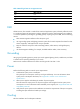
Figure 59 Removing the mounting brackets from the chassis 3. Put the mounting brackets into the box. Removing the cable management brackets The 11908-V has two cable management brackets—the one on the chassis bottom routes power cables, and the one on the chassis top routes other cables. To remove the cable management brackets: 1. Prepare the packing bag of the cable management brackets. Make sure the bag is clean, dry, and not damaged. 2.
Figure 60 Removing the cable management brackets from the 11908-V (1) Loosen the screws that attach the cable management brackets to the chassis. (2) Remove the cable management brackets. Repackaging the switch chassis 1. As shown in Figure 61, align the screw holes on the two sides of the chassis bottom to the L-type brackets on the pallet base of the wooden carton. 2. Screw in the screws shipped with your switch and fasten.
Figure 61 Installing the screws 3. Cover the chassis with the packing bag, and then tape the bag to the base pallet. 4. Install the side panels to the base pallet. 5. Put the accessories box and mounting bracket box into the wooden carton—at the clearance between the chassis and the wooden panel. 6. Cover the foam cushion to the chassis top, and make sure the surface of the foam cushion aligns to the upper rims of the wooden carton.
Index ESD wrist strap, 20 Numerics 19-inch rack authenticating user interface, 41 cabling recommendations, 86 B general cabling recommendations, 86 binding (cable management), 86 installing cable management brackets, 11, 12 installing mounting brackets, 11 bracket 19-inch rack cable management bracket installation), 11, 12 installing slide rail, 6 mounting bracket attachment to chassis, 12 19-inch rack cabling recommendations, 86 mounting cage nuts, 6, 10 19-inch rack general cabling recommendat
optical fiber technical specifications, 82 19-inch rack general cabling recommendations, 86 patch cord technical specifications, 82 19-inch rack mounting bracket attachment to chassis, 12 performance-based type technical specifications, 79 cooling and ventilation, 4 pigtail cord technical specifications, 83 grounding recommendation, 4 pin assignment technical specifications, 81 rack dimension requirements, 5 pinout technical specifications, 79 removing from rack, 92 pinout-based type technical s
D grounding, 4 DC power cable grounding switch through AC power supply PE wire, 17 connecting DC power cable, 27 grounding switch through DC power supply RTN wire, 18 technical specifications, 71 DC power supply grounding switch with grounding strip, 16 grounding switch through DC power supply RTN wire, 18 grounding the switch, 16 heat dissipation, 63 device module power consumption, 62 connecting switch to network, 35 power requirements, 4 installing fan tray, 55 power supply installation, 2
performance-based cable technical specifications, 79 ESD prevention, 2 pin assignment technical specifications, 81 removing the grounding cable, 90 grounding strip, 16 pinout-based cable technical specifications, 80 switch, 16 RJ-45 Ethernet port LED technical specification, 75 switch through AC power supply PE wire, 17 switch through DC power supply RTN wire, 18 twisted pair cable technical specifications, 78 switch with grounding strip, 16 examining installation site, 2 F verifying installatio
configuring basic settings, 32 heat dissipation, 63 humidity (installation site), 3 connecting physical ports, 33 I displaying configuration, 34 displaying running status, 34 ID (IRF member), 31 identifying master switch, 31 identifying identifying member switch physical ports, 32 IRF master switch, 31 installing member switch, 32 IRF member switch physical ports, 32 maintaining configuration, 34 installing maintaining running status, 34 19-inch rack cable management brackets, 11, 12 plannin
troubleshooting LPU failure, 48 management Ethernet port LED technical specifications, 73 M switch troubleshooting methods, 46 maintaining technical specifications, 65 IRF fabric configuration, 34 troubleshooting fan failure, 48 IRF fabric running status, 34 troubleshooting LPU failure, 48 making Ethernet twisted pair cable, 81 troubleshooting MPU failure, 48 master switch configuring IRF basic settings, 32 IRF fabric, 31 member troubleshooting switching fabric module failure, 48 N network conf
SC fiber connector technical specifications, 83 grounding switch through AC power supply PE wire, 17 single mode cable technical specifications, 82 grounding switch through DC power supply RTN wire, 18 single-mode patch cord, 82 P installation, 24 parameter (terminal), 36 LED, 73 patch cord technical specifications, 82 LED technical specifications, 76 PE wire, 17 removing the console cable, 90 physical port removing the grounding cable, 90 connecting, 33 removing the optical fiber, 91 identi
grounding switch through DC power supply RTN wire, 18 replacing QSFP+ cable, 56 grounding switch with grounding strip, 16 replacing QSFP+ transceiver module, 56, 56 replacing QSFP+ to SFP+ cable, 56 grounding the switch, 16 replacing SFP transceiver module, 56, 56 identifying IRF master switch, 31 replacing SFP+ cable, 56 identifying IRF member switch physical ports, 32 replacing SFP+ transceiver module, 56, 56 installing 19-inch rack cable management brackets, 11, 12 replacing transceiver modul
XFP transceiver module, 56 installing mounting brackets (19-inch rack), 11 installing slide rail (19-inch rack), 6 requirements (cable management), 86 mounting cage nuts (19-inch rack), 6, 10 RJ-45 mounting slide rail (19-inch rack), 6 connector technical specifications, 79 mounting switch to 19-inch rack, 13 Ethernet port LED technical specification, 75 mounting switch to workbench, 14 room dimensions (installation site), 5 removing cable management brackets, 93 RTN wire, 18 removing mounting
10-Gigabit SFP+ transceiver cable technical specifications, 68 connecting to network through twisted pair cables, 43 10-Gigabit SFP+ transceiver module technical specifications, 68 first time access, 35 cable technical specifications, 84 grounding, 16 general cabling recommendations, 86 connecting cable, 29 grounding through AC power supply PE wire, 17 connecting QSFP+ to SFP+ cable, 29 grounding through DC power supply RTN wire, 18 port LED technical specification, 75 grounding with grounding s
troubleshooting configuration terminal problems, 46 pigtail cord, 83 troubleshooting power supply system failure, 47 pinout-based cable type, 80 troubleshooting switch during operation, 47 power supply, 67 pin assignment, 81 system power consumption, 62, 63 power supply LEDs, 76 power supply weights and dimensions, 61 T QSFP+ cable, 84 technical specifications, 60 QSFP+ port LPU LEDs, 75 100-Mbps SFP transceiver modules, 68 QSFP+ to SFP+ cable, 84 10-Gigabit SFP+ transceiver cables, 68 QSFP+
MPU failure, 48 no terminal display, 46 power supply system failure, 47 switch, 46 switch during operation, 47 switching fabric module failure, 48 twisted pair cable network connection, 43 Ethernet twisted pair cable technical specifications, 78 making Ethernet twisted pair cable, 81 type cable technical specifications, 79 performance-based cable technical specifications, 79 pinout-based cable technical specifications, 80 U user interface authentication, 41 V ventilation (installation site), 4 verifying ins