
HP FlexFabric 11900 Switch Series Installation Guide


5
• Leave at least 10 cm (3.94 in) of clearance at the inlet and outlet air vents.
• The rack for the switch has a good cooling system.
• The installation site has a good cooling system.
• Verify that the airflow design of the chassis meets the airflow design of the installation site.
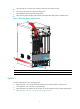
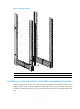
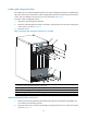
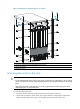
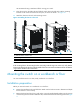
Figure 1 Airflow through the 11908-V Chassis
(1) Power supply air intake vents (2) Power supply
air exhaust vents
(3) Chassis air intake vents (4) Chassis
air
exhaust
vents
Space
For easy maintenance, follow these guidelines:
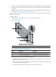
• Reserve at least 1 m (3.28 ft) of clearance between the rack and walls or other devices.
• The equipment room is at least 3 m (9.84 ft) high.
• Rack dimensions are sufficient for the chassis. For more information about chassis specifications,
see "Appendix A Chassis views and technical specifications."
1
2
4
3