HP FlexFabric 11900 Switch Series EVB Configuration Guide Part number: 5998-5269 Software version: Release 2111 and later Document version: 6W100-20140110
Legal and notice information © Copyright 2014 Hewlett-Packard Development Company, L.P. No part of this documentation may be reproduced or transmitted in any form or by any means without prior written consent of Hewlett-Packard Development Company, L.P. The information contained herein is subject to change without notice.
Contents Configuring EVB ··························································································································································· 1 Overview············································································································································································ 1 Basic concepts ···································································································································
Configuring EVB Edge Virtual Bridging (EVB) allows virtual machines (VMs) on a physical server to obtain bridge relay services through a common bridge port. It enables coordinated configuration and management of bridge services for VMs. Overview Data center virtualization includes network virtualization, storage virtualization, and server virtualization. Server virtualization uses specific virtualization software such as VMware to create VMs on a single physical server.
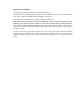
Basic concepts Figure 2 shows the components on the EVB station and EVB bridge. Figure 2 EVB architecture • Edge Relay (ER)—Transfers packets between one URP and one or more DRPs. An ER has one or more DRPs and one URP. Both URP and DRPs are called ER ports. An EVB station can have multiple ERs. • S-channel—A point-to-point S-VLAN established between a Port-mapping S-VLAN component in an EVB station and a Port-mapping S-VLAN component in an EVB bridge. An S-channel corresponds to the URP of an ER.
When a station creates a VM, it sends a VDP pre-associate, pre-associate with resource reservation, or associate packet to the bridge. The bridge sends the request to a VSI manager. The VSI manager notifies the bridge to create a VSI and apply policies. When a station shuts down a VM, it sends a VDP de-associate packet to the bridge. The bridge sends the request to the VSI manager. The VSI manager notifies the bridge to delete the VSI. Protocols and standards IEEE P802.1Qbg/D2.
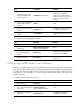
Do not enable both EVB and VLAN mapping, or both EVB and TRILL on the same interface. Do not execute the qinq enable or qinq ethernet-type command on an interface enabled with EVB, and vice versa. For more information about the two commands, see Layer 2—LAN Switching Command Reference. To enable EVB: Step Command Remarks 1. Enter system view. system-view N/A 2. Enter Layer 2 Ethernet interface view or Layer 2 aggregate interface view. interface interface-type interface-number N/A Enable EVB.
Step Command Remarks 1. Enter system view. system-view N/A 2. Specify a default VSI manager. evb default-manager { { ip ip-address | ipv6 ipv6-address | name name } [ port port-number ] | local-server } By default, no default VSI manager is specified. Configuring VDP negotiation parameters After a station sends a VDP request other than a De-Associate request to the bridge, the bridge requests the VSI resources and policies from the VSI manager.
Configuring an S-channel Creating an S-channel An S-channel is automatically created by CDCP, and the system automatically saves the configuration in the configuration file on the bridge. You can also manually create an S-channel by performing this task. If an (SCID, SVID) pair for an S-channel is created both automatically and manually, the one automatically created takes precedence. After an S-channel is created, an S-channel interface or S-channel aggregate interface is generated.
Step 3. 4. 5. 6. Command Remarks (Optional.) Configure the expected bandwidth of the S-channel interface. bandwidth bandwidth-value By default, the expected bandwidth of an S-channel interface is the default maximum bandwidth of the physical port to which the S-channel interface belongs. (Optional.) Restore the default settings for the S-channel interface. default N/A (Optional.) Configure a description for the S-channel interface.
Configuring MAC address learning for an S-channel You can manually disable the MAC address learning function for an S-channel by performing this task. To disable MAC address learning for an S-channel: Step Command Remarks 1. Enter system view. system-view N/A 2. Enter S-channel interface view or S-channel aggregate interface view. interface { s-channel | schannel-aggregation } interface-number:channel-id N/A By default, the MAC address learning function is enabled for an S-channel.
Step 3. Create a VSI or VSI aggregate interface. Command Remarks evb vsi vsi-local-id { association | pre-association } By default, no VSI or VSI aggregate interface exists on an S-channel. Configuring VSI filters The EVB bridge uses a VSI filter to identify VSI traffic for a VM. Filters are usually assigned by a VSI manager. You can manually create or remove VSI filters through this task. A VSI filter contains a set of VID values, MAC addresses, and group ID values.
• When a filter configured on a VSI aggregate interface contains information about a VLAN, you must not configure the filter on the same VSI aggregate interface again or on other VSI aggregate interfaces of the S-channel aggregate interface. If you do, an error message appears. • Activate a VSI aggregate interface after configuring a VSI filter, and deactivate a VSI aggregate interface before removing a VSI filter. To configure a VSI filter: Step Command Remarks 1. Enter system view.
Step Command Remarks 2. Enter VSI aggregate interface view. interface schannel-aggregation interface-number:channel-id.vsi-loc al-id N/A 3. (Optional.) Configure a description for the VSI aggregate interface. description text The default description information is "interface name Interface." Activate the VSI aggregate interface. evb vsi active By default, no VSI aggregate interface is activated. 4.
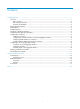
Figure 3 Network diagram Configuration procedure This section only contains EVB configurations. 1. Configure the EVB bridge: # Create VLAN 100 on EVB bridge 1. system-view [EVB_bridge1] vlan 100 [EVB_bridge1-vlan100] quit # Enable EVB on Ten-GigabitEthernet 1/0/1 that connects to EVB station 1, and configure Ten-GigabitEthernet 1/0/1 to operate in trunk mode.
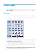
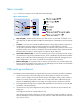
3. Configure the NMS: Use VAN Connection Manager of IMC on the NMS to configure network resources. The IMC PLAT 5.2 (E0401) and IMC CRM 5.2 (E0401) versions are used in this section. Figure 4 VAN Connection Manager To configure the NMS, log in to IMC, click the Resource tab, and select VAN Connection Manager from the navigation tree (see Figure 4), and perform the following steps: a.
Select Network from the navigation tree, click Add on the page that appears, enter For FTP for Name, 100 for VLAN ID, and 10 for Max. Connections, and click OK. The network name For FTP is displayed in the Network List page, as shown in Figure 6. Figure 6 Network List page c. Define the VSI type of VM 1: i Select VSI Type from the navigation tree. The VSI Type List page appears. ii Click Add. iii On the page that appears, do the following: − Enter VM1 VSI for Name.
− Select For FTP from the Network list, VM1 VSI from VSI Type, and VM1 VSI (V1) from VSI Type Version. iv Click OK. The connection VM1CON is displayed in the Connection List page, as shown in Figure 8. Figure 8 Connection List page 4. Verify the configuration: After VM 1 starts, the VAN Connection Manager service component of IMC deploys the VSI type VM1 VSI on EVB bridge 1. Only the R&D center can use the FTP service on VM 1.
Support and other resources Contacting HP For worldwide technical support information, see the HP support website: http://www.hp.
Conventions This section describes the conventions used in this documentation set. Command conventions Convention Description Boldface Bold text represents commands and keywords that you enter literally as shown. Italic Italic text represents arguments that you replace with actual values. [] Square brackets enclose syntax choices (keywords or arguments) that are optional. { x | y | ... } Braces enclose a set of required syntax choices separated by vertical bars, from which you select one.
Network topology icons Represents a generic network device, such as a router, switch, or firewall. Represents a routing-capable device, such as a router or Layer 3 switch. Represents a generic switch, such as a Layer 2 or Layer 3 switch, or a router that supports Layer 2 forwarding and other Layer 2 features. Represents an access controller, a unified wired-WLAN module, or the switching engine on a unified wired-WLAN switch. Represents an access point.
Index EVB default VSI manager, 4 A activating displaying EVB, 11 EVB VSI aggregate filter, 10 EVB VSI filter, 10 E edge relay (EVB), 2 B bridging EVB configuration, 1, 3, 11 EVB default VSI manager specification, 4 EVB LLDP configuration, 4 Edge Virtual Bridging.
configuring EVB S-channel VSI aggregate, 8 LLDP configuring EVB VDP negotiation parameter, 5 EVB LLDP configuration, 4 configuring EVB VSI filter, 9 M creating EVB S-channel, 6 MAC address creating EVB VSI, 8 EVB S-channel MAC address learning configuration, 8 creating EVB VSI aggregate, 8 displaying EVB, 11 maintaining enabling EVB, 3 EVB, 11 maintaining EVB, 11 N specifying EVB default VSI manager, 4 network protocols and standards EVB default VSI manager specification, 4 EVB LLDP confi
virtual EVB virtual station interface. See VSI Virtual Ethernet Bridge. Use VEB VSI configuration, 8 creation, 8 Discovery Configuration Protocol.