HP FlexFabric 11900 Switch Series FCoE Configuration Guide Part number: 5998-5267 Software version: Release 2111 and later Document version: 6W100-20140110
Legal and notice information © Copyright 2014 Hewlett-Packard Development Company, L.P. No part of this documentation may be reproduced or transmitted in any form or by any means without prior written consent of Hewlett-Packard Development Company, L.P. The information contained herein is subject to change without notice.
Contents FCoE overview ····························································································································································· 1 Storage area network ······················································································································································· 1 FC SAN ···················································································································································
Setting up a fabric ····················································································································································· 29 Overview········································································································································································· 29 Principal switch selection ···································································································································
FSPF routes ····························································································································································· 65 Configuring static routes for FC ···································································································································· 66 Configuration restrictions and guidelines ··········································································································· 66 Configuration pro
Disruptive load balancing ···································································································································· 97 NPV configuration task list ············································································································································ 97 Configuring uplink interfaces and downlink interfaces ······························································································ 97 Configuring uplink interfa
FCoE overview The switch supports FCoE only when operating in advanced mode. For more information about system operating modes, see Fundamentals Configuration Guide. In an FCoE network, HP recommends that you set the delay for the IRF ports to report a link down event as 0 on IRF member devices. For more information, see the irf link-delay command in Fundamentals Command Reference.
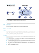
Figure 1 FC SAN networking NOTE: • An FC SAN refers to a network comprising FC switches and nodes. • A fabric refers to a transmission network comprising FC switches. FC protocol The servers, FC switches, and disk devices in an FC SAN must all support FC. Basic concepts WWN The World Wide Name (WWN) is a 64-bit address that identifies a fabric or an entity (such as an FC switch, node, or port) in an FC SAN. The upper-layer protocol of FC uses WWNs for communication.
Figure 2 Structure of an FC address A Domain_ID can uniquely identify an FC switch. Different FC switches in the same fabric have different Domain_IDs. An FC address can uniquely identify an N_Port on a node. Different N_Ports on the same node have different FC addresses. FC switches use Domain_IDs to route messages between each other. The FC protocol standardizes the FC address usage. For more information, see "Appendixes.
Figure 4 FC SAN communication model The following takes a server accessing a disk device as an example to see how data communication occurs in an FC SAN. 1. The server and the disk device use the fabric login (FLOGI) protocol to register with the FC switches, which then assign FC addresses to each directly-connected node. A FLOGI packet contains such information as the port WWN, node WWN, and the expected FC address. 2.
Zoning can solve the preceding problem by dividing a VSAN into zones and adding N_Ports to different zones for different purposes. In this manner, N_Ports in different zones are separated to implement access control. For more information about FC zones, see "Configuring FC zones." FCoE A data center using the FC SAN technology usually comprises separate local area networks (LANs) and SANs. LANs carry traditional Ethernet/IP services, and SANs carry network storage services.
Figure 6 FCoE network diagram VFC interface and VN interface A virtual fiber channel (VFC) interface is a logical interface manually created on the FCF switch to simulate the function of a physical FC interface. To use a VFC interface, bind it to a physical Ethernet interface. You can connect either an ENode or an FCF switch to a VFC interface. VFC interfaces support E mode, F mode (default), and NP mode.
Figure 7 FPMA composition How FCoE works Figure 8 Block diagrams of the ENode and the FCF switch ENode FCF VN interface Virtual link VFC interface FC layer FC layer Ethernet layer Ethernet layer Ethernet interface Ethernet interface NOTE: This section describes how FCoE works only on the FCF switch, rather than on the ENode.
Figure 9 FIP operation ENode FCF (1) Send Discovery Solicitation Learn FCoE MAC address (2) Send solicited Discovery Advertisement (3) Send solicited Discovery Advertisements periodically (4) Send FLOGI request Check FCoE MAC address (5) Send FLOGI LS_ACC (6) Send solicited Discovery Advertisements periodically As shown in Figure 9, the following workflow is used to set up a virtual link: 1. The ENode sends a Discovery Solicitation containing its FCoE MAC address. 2.
• FCF mode—A switch operating in this mode is called an FCF switch. Its VFC interfaces support E mode (E_Port) and F mode (F_Port). • NPV mode—A switch operating in this mode is called an N_Port Virtualization (NPV) switch. Its VFC interfaces support F mode (F_Port) and NP mode (NP_Port). • Transit mode—A switch operating in this mode is called a Transit switch. Its Ethernet interfaces can operate in ENode mode or FCF mode.
NPV mode An FC SAN needs a large number of edge switches that are connected directly to nodes. NPV switches are developed to expand the number of switches in an FC SAN. Figure 11 NPV network diagram As shown in Figure 11, the NPV switch resides between nodes and the core switch on the edge of the fabric. The core switch is a switch operating in FCF mode. The NPV switch is connected to the nodes through its F_Ports and to the core switch through its NP_Port.
Figure 13 Transit cascading network diagram Figure 14 shows a network scenario where both Transit and NPV switches are present. Figure 14 Network diagram for NPV and Transit switches The primary responsibilities of Transit switches are filtering and forwarding FCoE protocol packets. They can recognize and control FCoE packets as compared to standard Ethernet switches, but they do not provide FCoE traffic processing capabilities as complex as FCF switches or NPV switches.
Configuring an FCoE mode The switch supports FCoE only when operating in advanced mode. For more information about system operating modes, see Fundamentals Configuration Guide. FCoE features supported in different FCoE modes The switch supports three FCoE modes: FCF mode, NPV mode, and Transit mode. Each mode has different features as shown in Table 1. You can choose to configure different features based on the FCoE mode of a switch.
To configure an FCoE mode for a switch: Step Command Remarks 1. Enter system view. system-view N/A 2. Configure an FCoE mode for the switch. fcoe-mode { fcf | npv | transit } By default, a switch operates in non-FCoE mode. 3. Display the FCoE mode of the switch. display fcoe-mode This command can be executed in any view.
Configuring VFC interfaces and FIP VFC interfaces and FIP configuration task list Tasks at a glance (Required.) Configuring a VFC interface (Required.) Enabling FCoE for a VLAN and mapping a VSAN to the VLAN (Optional.) Configuring the FC-MAP value (Optional.) Configuring the FKA advertisement period value (Optional.) Configuring the FCF priority Configuring a VFC interface Step Command Remarks 1. Enter system view. system-view N/A 2. Create a VFC interface and enter its view.
Step 8. 9. Command Remarks (Optional.) Restore the default settings for the VFC interface. default N/A Bring up the VFC interface. undo shutdown By default, a VFC interface is up. Enabling FCoE for a VLAN and mapping a VSAN to the VLAN When you use a VFC interface to transmit packets, the Ethernet interface bound to the VFC interface may allow multiple VLANs.
Configuring the FC-MAP value IMPORTANT: After FC-MAP values are configured, VFC interfaces perform a renegotiation. The same FC-MAP value is required for two VFC interfaces to negotiate successfully. The FC-MAP value identifies an FCoE network. Switches in the same FCoE network must have the same FC-MAP value. To configure an FC-MAP value: Step Command Remarks 1. Enter system view. system-view N/A 2. Configure an FC-MAP value. fcoe fcmap fc-map The default setting is 0x0EFC00.
Table 2 Recommended values for different application scenarios Recommended value Less than 90 seconds 60–90 seconds 300–600 seconds Application scenarios Remarks Connected to servers, storage devices, or third-party switches. Active/standby switchover on the switch takes more than 2.5 x 60 seconds because of the amount of FCoE configuration. ISSU reboot on a dual-MPU switch takes more than 2.5 x 60 seconds because of the amount of FCoE configuration.
An ENode selects the FCF switch with the highest priority from the FCF switches sending Discovery Advertisements and sends a FLOGI request to it for login. The FCF priority is effective only on a VFC interface connected to an ENode (VFC interface in F mode). Configuring the system FCF priority Step Command Remarks N/A 1. Enter system view. system-view 2. Configure the system FCF priority. fcoe global fcf-priority priority The default setting is 128.
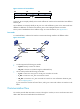
Figure 15 Network diagram LAN Ethernet switch SAN VFC2 XGE1/0/2 FCF switch Switch B VFC2 XGE1/0/2 FCF switch Switch A VFC1 XGE1/0/1 Ethernet Server FCoE Configuration procedure This section describes the configurations for VFC interfaces and FIP on the FCF switch. 1. Configure Switch A: # Configure the switch to operate in advanced mode, save the configuration, and reboot the switch. (Skip this step if the switch is operating in advanced mode.
# Create a class named app_c with the logic OR operator, and specify ACL 4000 as the match criterion. [SwitchA] traffic classifier app_c operator or [SwitchA-classifier-app_c] if-match acl 4000 [SwitchA-classifier-app_c] quit # Create a behavior named app_b, and configure the action of marking packets with 802.1p priority 3.
[SwitchA-Ten-GigabitEthernet1/0/1] port trunk permit vlan 20 [SwitchA-Ten-GigabitEthernet1/0/1] quit # Create interface VFC 2, and configure it to operate in E mode. [SwitchA] interface vfc 2 [SwitchA-Vfc2] fc mode e # Bind interface VFC 2 to interface Ten-GigabitEthernet 1/0/2, and assign it to VSAN 10 as a trunk port. [SwitchA-Vfc2] bind interface ten-gigabitethernet 1/0/2 [SwitchA-Vfc2] port trunk vsan 10 [SwitchA-Vfc2] quit # Assign interface Ten-GigabitEthernet 1/0/2 to VLAN 20 as a trunk port.
[SwitchB-Ten-GigabitEthernet1/0/2] port link-type trunk [SwitchB-Ten-GigabitEthernet1/0/2] port trunk permit vlan 20 [SwitchB-Ten-GigabitEthernet1/0/2] quit # Enable FCoE for VLAN 20 and map VLAN 20 to VSAN 10. [SwitchB] vlan 20 [SwitchB-vlan20] fcoe enable vsan 10 [SwitchB-vlan20] quit # Permit the members in the default zone in VSAN 10 to access each other.
Configuring FIP snooping Overview A node must register with an FC fabric to communicate with devices in the FC SAN. An FC switch has point-to-point connections with nodes and brings up an interface connected to a node only after the node completes fabric login on the interface. In an FCoE implementation, Transit switches can be present between ENodes and FCF switches, so the connections between ENodes and FCF switches are no longer point-to-point.
To facilitate description, the following definitions are specified: • FIP snooping rules generated on an Ethernet interface operating in FCF mode are called FCF FIP snooping rules. • FIP snooping rules generated on an Ethernet interface operating in ENode mode are called ENode FIP snooping rules. Establishing FIP snooping rules FIP snooping rules are established during the setup of a virtual link between an ENode and an FCF switch. The following workflow is used to establish FIP snooping rules: 1.
To enable FIP snooping: Step Command Remarks 1. Enter system view. system-view N/A 2. Enter VLAN view. vlan vlan-id N/A 3. Enable FIP snooping. fip-snooping enable By default, FIP snooping is disabled. Configuring the operating mode of an Ethernet interface Ethernet interfaces on a Transit switch can operate in ENode mode or FCF mode.
Displaying and maintaining FIP snooping Execute display commands in any view. Task Command Display ENode information obtained by a Transit switch. display fip-snooping enode [ vlan vlan-id ] Display FCF switch information obtained by a Transit switch. display fip-snooping fcf [ vlan vlan-id ] Display the FIP snooping rules that have been flushed (in standalone mode).
[SwitchA] fcoe-mode transit # Create VLAN 10, and enable FIP snooping for VLAN 10. [SwitchA] vlan 10 [SwitchA-vlan10] fip-snooping enable [SwitchA-vlan10] quit # Assign interface Ten-GigabitEthernet 1/0/1 to VLAN 10, and configure the interface to operate in ENode mode.
[SwitchB-Vfc2] bind interface ten-gigabitethernet 1/0/2 [SwitchB-Vfc2] port trunk vsan 10 [SwitchB-Vfc2] quit # Assign Ten-GigabitEthernet 1/0/2 to VLAN 10 as a trunk port. [SwitchB] interface ten-gigabitethernet 1/0/2 [SwitchB-Ten-GigabitEthernet1/0/2] port link-mode bridge [SwitchB-Ten-GigabitEthernet1/0/2] port link-type trunk [SwitchB-Ten-GigabitEthernet1/0/2] port trunk permit vlan 10 [SwitchB-Ten-GigabitEthernet1/0/2] quit # Enable FCoE for VLAN 10 and map VLAN 10 to VSAN 10.
Setting up a fabric Overview A fabric transmits data for servers and disk devices. When setting up a fabric, you must assign a domain ID to each FCF switch in the fabric and assign an FC address to each node connected to the fabric. You can build a fabric through one of the following modes: • Static mode—You must manually assign domain IDs to all switches in the network, and then each switch assigns FC addresses to the N_Ports connected to it.
in the packet is higher, or the priority in the packet is the same and the WWN is smaller, the switch replaces the locally-record principal switch information with the principal switch information recorded in the packet, and notifies the other switches. Finally, all switches in the network make an agreement on which switch is the principal switch. 3. When the PSST times out, if the locally-recorded principal switch information is the local switch, the switch becomes the principal switch.
{ { 5. If the downstream switch has been configured with a static domain ID and the static domain ID is different from the one assigned by the principal switch, or if the principal switch notifies the downstream switch that no domain ID can be assigned, the downstream switch isolates its upstream principal link and brings down the relevant interface. For more information about domain ID types, see "Configuring a domain ID for a switch.
Tasks at a glance Remarks (Required.) Configuring a domain ID for a switch When statically building a fabric, you must manually configure a domain ID for each switch. (Optional.) Configuring the mapping between the N_Port WWN and an FC address N/A (Optional.) Configuring the fabric timers N/A (Optional.) Configuring RSCN aggregation N/A (Optional.) Configuring and obtaining FC4 information of nodes N/A Building a fabric dynamically Tasks at a glance Remarks (Required.
Step Command Remarks 1. Enter system view. system-view N/A 2. Enter VSAN view. vsan vsan-id N/A 3. Enable the fabric configuration function. domain configure enable Enable or disable the function for all switches in the VSAN as required. Disable the fabric configuration function. undo domain configure enable 4. By default, the fabric configuration function is enabled. Setting a fabric name The fabric name configured takes effect only on a statically-built fabric.
Step Command Remarks 1. Enter system view. system-view N/A 2. Enter VSAN view. vsan vsan-id N/A 3. Configure a priority value for the switch. priority value By default, the priority value of a switch is 128. Configuring the allowed domain ID list Configuring the allowed domain ID list has an effect on switches as follows: • Principal switch—Can only assign domains IDs within the allowed domain ID list.
HP recommends that you configure domain IDs of the same type for all switches in a VSAN. To configure a domain ID for a switch: Step Command Remarks 1. Enter system view. system-view N/A 2. Enter VSAN view. vsan vsan-id N/A 3. Configure a domain ID for the switch. domain-id domain-id { preferred | static } By default, the domain ID of a switch is 0 and is of the preferred type.
If you perform the configuration in both system view and VSAN view, the configuration made in VSAN view applies to the VSAN. Configuring the fabric timers in system view Step Command Remarks 1. Enter system view. system-view N/A 2. Configure the global distributed service timeout period. fc timer distributed-services value By default, the distributed service timeout period is 5000 milliseconds. 3. Configure the global error detection timeout period.
• Disruptive reconfiguration—Floods the Reconfigure Fabric (RCF) frames throughout the fabric, and notifies all switches to perform a disruptive reconfiguration. During the reconfiguration procedure, each switch clears all data for renegotiation, and data transmission in the fabric is disrupted. • Non-disruptive reconfiguration—Floods the Build Fabric (BF) frames throughout the fabric, and notifies all switches to perform a non-disruptive reconfiguration.
Step Command Remarks 1. Enter system view. system-view N/A 2. Enter VFC interface view. interface vfc interface-number N/A 3. Configure the interface to reject the received RCF requests. fc domain rcf-reject vsan vsan-id By default, a VFC interface does not reject the received RCF requests. Configuring RSCN aggregation RSCN overview An FC switch uses a name service database to store information about registered nodes on the local switch and on remote switches in the fabric.
Step Command Remarks 2. Enter VSAN view. vsan vsan-id N/A 3. Enable RSCN aggregation. rscn aggregation enable By default, RSCN aggregation is disabled. The default setting is 2000 ms. 4. Set the RSCN aggregation timer. rscn aggregation timer time You can adjust this timer to control the frequency the switch responds to node information changes based on switch performance.
Step Command Remarks 1. Enter system view. system-view N/A 2. Enter VSAN view. vsan vsan-id N/A 3. Enable auto discovery of SCSI-FCP information. fc name-service auto-discovery By default, auto discovery of SCSI-FCP information is enabled. Configuring the default FC4 information for a node If a node does not register FC4 information and the switch fails to obtain SCSI-FCP information from the node, the switch records the default FC4 information in the name service database for that node.
Static fabric building configuration example Network requirements As shown in Figure 19, use the static approach to build a fabric. Figure 19 Network diagram Configuration procedure 1. Configure Switch A: # Configure the switch to operate in advanced mode, save the configuration, and reboot the switch. (Skip this step if the switch is operating in advanced mode.
[SwitchA] acl number 4000 [SwitchA-acl-ethernetframe-4000] rule permit type 8906 ffff [SwitchA-acl-ethernetframe-4000] rule permit type 8914 ffff [SwitchA-acl-ethernetframe-4000] quit # Create a class named app_c with the logic OR operator, and specify ACL 4000 as the match criterion. [SwitchA] traffic classifier app_c operator or [SwitchA-classifier-app_c] if-match acl 4000 [SwitchA-classifier-app_c] quit # Create a behavior named app_b, and configure the action of marking packets with 802.1p priority 3.
[SwitchA-Vfc1] quit # Assign interface Ten-GigabitEthernet 1/0/1 to VLAN 10 as a trunk port. [SwitchA] interface ten-gigabitethernet 1/0/1 [SwitchA-Ten-GigabitEthernet1/0/1] port link-type trunk [SwitchA-Ten-GigabitEthernet1/0/1] port trunk permit vlan 10 [SwitchA-Ten-GigabitEthernet1/0/1] quit # Create interface VFC 2, and configure it to operate in E mode.
e? [Y/N]:y [SwitchB-vsan1] quit # Enable LLDP globally. [SwitchB] lldp global enable # Enable LLDP on interface Ten-GigabitEthernet 1/0/1, and enable the interface to advertise DCBX TLVs.
# Enable interface Ten-GigabitEthernet 1/0/1 to automatically negotiate with its peer to decide whether to enable PFC, enable PFC for 802.1p priority 3, and configure Ten-GigabitEthernet 1/0/1 to trust the 802.1p priority carried in packets.
Domain Information of VSAN 1: Running time information: State: Stable Switch WWN: 48:33:43:2d:46:43:1A:1A Fabric name: 11:11:11:11:11:11:11:11 Priority: 128 Domain ID: 1 Configuration information: Domain configure: Disabled Domain auto-reconfigure: Disabled Fabric name: 11:11:11:11:11:11:11:11 Priority: 128 Domain ID: 1 (static) Principal switch running time information: Priority: 128 No interfaces available.
Dynamic fabric building configuration example Network requirements As shown in Figure 20, use the dynamic approach to build a fabric. Figure 20 Network diagram Configuration procedure 1. Configure Switch A: # Configure the switch to operate in advanced mode, save the configuration, and reboot the switch. (Skip this step if the switch is operating in advanced mode.
[SwitchA-Vfc1] quit # Assign interface Ten-GigabitEthernet 1/0/1 to VLAN 10 as a trunk port. [SwitchA] interface ten-gigabitethernet 1/0/1 [SwitchA-Ten-GigabitEthernet1/0/1] port link-type trunk [SwitchA-Ten-GigabitEthernet1/0/1] port trunk permit vlan 10 [SwitchA-Ten-GigabitEthernet1/0/1] quit # Create interface VFC 2, and configure it to operate in E mode.
[SwitchB-Vfc1] fc mode e # Bind interface VFC 1 to interface Ten-GigabitEthernet 1/0/1, and assign it to VSAN 1 as a trunk port. [SwitchB-Vfc1] bind interface ten-gigabitethernet 1/0/1 [SwitchB-Vfc1] port trunk vsan 1 [SwitchB-Vfc1] quit # Assign interface Ten-GigabitEthernet 1/0/1 to VLAN 10 as a trunk port.
# Configure the switch to operate in advanced mode, save the configuration, and reboot the switch. (Skip this step if the switch is operating in advanced mode.) system-view [SwitchC] system-working-mode advance Do you want to change the system working mode? [Y/N]:y The system working mode is changed, please save the configuration and reboot the system to make it effective. # Configure the switch to operate in FCF mode, and enable the fabric configuration function in VSAN 1.
# Apply the QoS policy plcy to the outbound direction of interface Ten-GigabitEthernet 1/0/3. [SwitchC] interface ten-gigabitethernet 1/0/3 [SwitchC-Ten-GigabitEthernet1/0/3] qos apply policy plcy outbound [SwitchC-Ten-GigabitEthernet1/0/3] quit # Map 802.1p priority 3 to local precedence 3 in the outbound direction. (This is the default mapping, and you can modify the mapping as needed.
# Create interface VFC 3, and configure it to operate in F mode. [SwitchC] interface vfc 3 [SwitchC-Vfc3] fc mode f # Bind interface VFC 3 to interface Ten-GigabitEthernet 1/0/3, and assign it to VSAN 1 as a trunk port. [SwitchC-Vfc3] bind interface ten-gigabitethernet 1/0/3 [SwitchC-Vfc3] port trunk vsan 1 [SwitchC-Vfc3] quit # Assign interface Ten-GigabitEthernet 1/0/3 to VLAN 10 as a trunk port.
[SwitchD-Ten-GigabitEthernet1/0/2] lldp tlv-enable dot1-tlv dcbx [SwitchD-Ten-GigabitEthernet1/0/2] quit # Create an Ethernet frame header ACL numbered 4000, and configure two rules in the ACL to match FCoE frames (protocol type 0x8906) and FIP frames (protocol type 0x8914).
# Bind interface VFC 1 to interface Ten-GigabitEthernet 1/0/1, and assign it to VSAN 1 as a trunk port. [SwitchD-Vfc1] bind interface ten-gigabitethernet 1/0/1 [SwitchD-Vfc1] port trunk vsan 1 [SwitchD-Vfc1] quit # Assign interface Ten-GigabitEthernet 1/0/1 to VLAN 10 as a trunk port.
Domain auto-reconfigure: Disabled Fabric name: 48:33:43:2d:46:43:1A:1A Priority: 128 Domain ID: 11 (preferred) Principal switch running time information: Priority: 1 Path Interface Upstream Vfc1 Downstream Vfc2 The output shows that the domain configuration is complete and that the principal switch assigns domain ID 11 to Switch A. # Display the domain ID list of VSAN 1.
Configuring VSAN Overview The virtual storage area network (VSAN) technology breaks a physical SAN into multiple VSANs, and provides more secure, reliable, and flexible services. Devices in a VSAN cannot get information about any other VSAN and devices in any other VSAN. Each VSAN performs the following operations independently: selecting a principal switch, assigning domain IDs, running routing protocols, maintaining routing table and FIB table, and providing services.
Creating a VSAN Initially, only the default VSAN (VSAN 1) exists. You cannot create or delete VSAN 1. You can create VSANs 2 to 3839. To create a VSAN: Step Command Remarks 1. Enter system view. system-view N/A 2. Create a VSAN and enter VSAN view. vsan vsan-id By default, only the default VSAN (VSAN 1) exists. Configuring a trunk VSAN A VFC interface can be assigned to multiple VSANs as a trunk port.
• Server B can read and write only the data of Disk C. Figure 21 Network diagram Configuration considerations • To meet these requirements, divide the SAN into two VSANs, VSAN 10 and VSAN 20. Each VSAN contains a server and disk devices that can exchange data. • Configure the two interfaces connecting Switch A to the servers to operate in F mode, and assign the two interfaces as trunk ports to VSAN 10 and VSAN 20.
[SwitchA-vsan20] quit # Enable LLDP globally. [SwitchA] lldp global enable # Enable LLDP on interface Ten-GigabitEthernet 1/0/1, and enable the interface to advertise DCBX TLVs. [SwitchA] interface ten-gigabitethernet 1/0/1 [SwitchA-Ten-GigabitEthernet1/0/1] lldp enable [SwitchA-Ten-GigabitEthernet1/0/1] lldp tlv-enable dot1-tlv dcbx [SwitchA-Ten-GigabitEthernet1/0/1] quit # Enable LLDP on interface Ten-GigabitEthernet 1/0/2, and enable the interface to advertise DCBX TLVs.
[SwitchA-maptbl-out-dot1p-lp] import 3 export 3 [SwitchA-maptbl-out-dot1p-lp] quit # Enable byte-count WRR on interface Ten-GigabitEthernet 1/0/1, and configure queue 3 to use strict priority (SP) queuing. [SwitchA] interface ten-gigabitethernet 1/0/1 [SwitchA-Ten-GigabitEthernet1/0/1] qos wrr byte-count [SwitchA-Ten-GigabitEthernet1/0/1] qos wrr 3 group sp # Enable byte-count WRR on interface Ten-GigabitEthernet 1/0/2, and configure queue 3 to use SP queuing.
[SwitchA-Vfc2] bind interface ten-gigabitethernet 1/0/2 [SwitchA-Vfc2] port trunk vsan 20 [SwitchA-Vfc2] quit # Assign interface Ten-GigabitEthernet 1/0/2 to VLAN 10 as a trunk port. [SwitchA] interface ten-gigabitethernet 1/0/2 [SwitchA-Ten-GigabitEthernet1/0/2] port link-type trunk [SwitchA-Ten-GigabitEthernet1/0/2] port trunk permit vlan 10 [SwitchA-Ten-GigabitEthernet1/0/2] quit # Create interface VFC 4, and configure it to operate in E mode.
VSAN 10: Access Ports: Trunk Ports: Vfc1 Vfc4 VSAN 20: Access Ports: Trunk Ports: Vfc2 Vfc4 2. Verify the configuration on Switch B. The output on Switch B is the same as that on Switch A.
Configuring FC routing and forwarding Overview Routing and forwarding in an FC SAN is achieved through FCF switches. When an FCF switch receives a packet, the FCF switch selects an optimal route based on the destination address and forwards the packet to the next FCF switch in the path until the packet reaches the last FCF switch, which forwards the packet to the destination node. Routing provides the path information that guides the forwarding of packets.
• Protocol—Protocol type, which can be DIRECT (direct routes), STATIC (static routes), or FSPF (FSPF routes). • Preference—There might be direct routes, static routes, and FSPF routes to the same destination. All of these types of routes are assigned preferences. Direct routes have a preference of 0, static routes have a preference of 10, and FSPF routes have a preference of 20. The optimal route is the one with the highest priority (smallest preference value). • Cost—Cost of the route.
Static routes Static routes are manually configured by the administrator. After you configure a static route, an FC frame to the specified destination is forwarded along the path specified by the administrator. In a simple network, static routes are enough for implementing network connectivity. By correctly setting and using static routes, you can improve network performance and guarantee bandwidth for critical network applications.
{ Cost for packet transmission over the link. Each link has a different cost. The smaller the cost, the better the link. The route selection algorithm uses this value to determine the best route. The interface cost is configurable. FSPF packet types The following protocol packets are used in FSPF: • Hello packets—Sent periodically to discover and maintain FSPF neighbors. • Link state update (LSU)—Advertises local link state information in LSRs to the neighboring switches.
Step Command Remarks 1. Enter system view. system-view N/A 2. Enter VSAN view. vsan vsan-id N/A 3. Configure a static FC route. fc route-static fcid { mask | mask-length } interface-type interface-number [ cost cost-value ] By default, no static FC route exists. Configuring FSPF FSPF is enabled by default. Typically, you do not need to make special configurations. You can change FSPF parameters on a per-VSAN or per-interface basis as needed.
Configuring the shortest SPF calculation interval SPF calculations occur when the LSDB changes. To limit the amount of CPU resources consumed by frequent SPF calculations, you can change the shortest SPF calculation interval. The shortest SPF calculation interval defines the minimum interval between two consecutive SPF calculations. A smaller value means that FSPF responds faster to fabric changes by recalculating routes in a VSAN, but it requires more CPU resources.
Configuring the FSPF cost for an interface Each link has a different cost. The route selection algorithm uses this value to determine the best route. The smaller the interface FSPF cost, the smaller the link cost. To configure the interface FSPF cost: Step Command Remarks 1. Enter system view. system-view N/A 2. Enter VFC interface view. interface vfc interface-number N/A 3. Configure the FSPF cost for the interface in a specified VSAN. fspf cost value vsan vsan-id The default is 100.
Step Command Remarks 1. Enter system view. system-view N/A 2. Enter VFC interface view. interface vfc interface-number N/A 3. Configure the dead interval for the interface in a specified VSAN. fspf dead-interval value vsan vsan-id The default setting is 80 seconds. Configuring the LSR retransmission interval for interfaces The LSR retransmission interval specifies the time to wait for an LSR acknowledgement from the neighbor before retransmitting the LSR.
Configuring the GR restarter Step Command Remarks 1. Enter system view. system-view N/A 2. Enable FSPF GR. fspf graceful-restart By default, FSPF GR is disabled. 3. Configure the maximum interval for FSPF GR. fspf graceful-restart interval interval-value The default setting is 120 seconds. Command Remarks Configuring the GR helper Step 1. Enter system view. system-view N/A 2. Enable FSPF GR helper. fspf graceful-restart helper By default, FSPF GR helper is enabled.
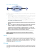
Static FC routing configuration example Network requirements As shown in Figure 22, configure static routes to enable any two FCF switches to communicate with each other. Figure 22 Network diagram Switch B Domain ID: 2 VFC1 XGE1/0/1 VFC2 XGE1/0/2 VFC1 XGE1/0/1 VFC2 XGE1/0/2 Switch A Domain ID: 1 Switch C Domain ID: 3 Configuration procedure 1. Configure Switch A: # Configure the switch to operate in advanced mode, save the configuration, and reboot the switch.
# Bind interface VFC 1 to interface Ten-GigabitEthernet 1/0/1, and assign it to VSAN 1 as a trunk port. [SwitchA-Vfc1] bind interface ten-gigabitethernet 1/0/1 [SwitchA-Vfc1] port trunk vsan 1 [SwitchA-Vfc1] quit # Assign interface Ten-GigabitEthernet 1/0/1 to VLAN 10 as a trunk port.
# Bind interface VFC 1 to interface Ten-GigabitEthernet 1/0/1, and assign it to VSAN 1 as a trunk port. [SwitchB-Vfc1] bind interface ten-gigabitethernet 1/0/1 [SwitchB-Vfc1] port trunk vsan 1 [SwitchB-Vfc1] quit # Assign interface Ten-GigabitEthernet 1/0/1 to VLAN 10 as a trunk port.
system-view [SwitchC] fcoe-mode fcf [SwitchC] vsan 1 [SwitchC-vsan1] domain configure enable # Configure the domain ID as 3. [SwitchC-vsan1] domain-id 3 static Non-disruptive reconfiguration or isolating the switch may be performed. Continu e? [Y/N]:y [SwitchC-vsan1] quit # Create interface VFC 2, and configure it to operate in E mode. [SwitchC] interface vfc 2 [SwitchC-Vfc2] fc mode e # Bind interface VFC 2 to interface Ten-GigabitEthernet 1/0/2, and assign it to VSAN 1 as a trunk port.
0xfffffc/24 DIRECT 0 0 InLoop0 0xfffffd/24 DIRECT 0 0 InLoop0 # Display the FC routing table in VSAN 1 on Switch B.
Figure 23 Network diagram Configuration procedure 1. Configure Switch A: # Configure the switch to operate in advanced mode, save the configuration, and reboot the switch. (Skip this step if the switch is operating in advanced mode.) system-view [SwitchA] system-working-mode advance Do you want to change the system working mode? [Y/N]:y The system working mode is changed, please save the configuration and reboot the system to make it effective.
# Permit the members in the default zone in VSAN 2 to access each other. [SwitchA] vsan 2 [SwitchA-vsan2] zone default-zone permit [SwitchA-vsan2] quit # Enable FSPF on interface VFC 1. [SwitchA] interface vfc 1 [SwitchA-Vfc1] port trunk vsan 2 [SwitchA-Vfc1] undo fspf silent vsan 2 [SwitchA-Vfc1] quit 2. Configure Switch B: # Configure the switch to operate in advanced mode, save the configuration, and reboot the switch. (Skip this step if the switch is operating in advanced mode.
[SwitchB-vlan10] quit # Permit the members in the default zone in VSAN 2 to access each other. [SwitchB] vsan 2 [SwitchB-vsan2] zone default-zone permit [SwitchB-vsan2] quit # Enable FSPF on interface VFC 1. [SwitchB] interface vfc 1 [SwitchB-Vfc1] port trunk vsan 2 [SwitchB-Vfc1] undo fspf silent vsan 2 [SwitchB-Vfc1] quit Verifying the configuration # Display FSPF neighbor information on Switch A.
Configuring FC zones Overview The VSAN technology divides a physical SAN into multiple VSANs, which are separated from one another, and provides more secure, reliable, and flexible services. A VSAN, however, cannot perform access control over the servers and disk devices (or the N_Ports) connected to a fabric. N_Ports in the same VSAN can access one another only if these N_Ports register name services. This creates data security risks.
• Each VSAN can have multiple zone sets, each zone set can have multiple zones, and each zone can have multiple zone members. • To facilitate configuration, zone membership configuration supports use of zone aliases. A zone alias is a set of N_Ports, which can be considered as a whole. You can add common zone members in multiple zones to a zone alias, and call the zone alias in different zones to simplify configuration.
Default zone The N_Ports in zones of the active zone set are part of the active zone set. Registered N_Ports that are not in the active zone set automatically become part of the default zone. If members of the default zone are allowed to access each other, the default zone can be considered to be part of the active zone set, and it participates in access control among N_Ports. Otherwise, the default zone is not in the active zone set and does not participate in access control among the N_Ports.
Figure 26 Distribution process The distribution process is as follows: 1. The manager switch obtains the status of each managed switch through an ACA request, which carries the fabric-wide list of domain IDs (addresses of all switches in the fabric) known to the manager switch. After sending the ACA request, the manager switch enters the locked state. After receiving the ACA request, a managed switch compares its list of domain IDs with that in the packet.
7. After receiving the RCA request, the managed switch releases its change authorization state and replies with an ACC packet. 8. The manager switch releases its change authorization state after receiving ACC packets from all managed switches. NOTE: • [1] This actually requires the routing information across the fabric to be correct and consistent and eliminating unreachable routes. You need to pay special attention to this in the case of using static routes.
Figure 27 Zone merge process between two switches The zone merge process is as follows: 1. Switch A and Switch B are new neighbors to each other. Suppose that Switch A first initiates a merge to Switch B: a. Switch A sends an MRRA request carrying the size of its data to be merged to Switch B. b. After receiving the MRRA request, Switch B determines whether to accept the merge according to its local data size. If the size of the data to be merged is acceptable, it replies with an ACC packet.
NOTE: Consistent active zone sets among switches can be achieved by a merge. Consistent zone databases achieved after a merge, however, require all participating switches to be configured with complete merge. Zone merge rules Table 4 Zone merge rules Local database Neighbor database Merge status Merge result Successful The union of the local database and neighbor database. Zone sets with the same name are merged. Successful The union of the local database and neighbor database.
Tasks at a glance (Required.) Configuring the default zone policy (Required.) Configuring zone distribution and merge types (Required.) Activating a zone set and distributing it to the entire fabric (Optional.) Triggering a complete distribution (Optional.) Renaming zone aliases, zones, and zone sets (Optional.) Copying zone aliases, zones, and zone sets (Optional.) Deleting the zone database NOTE: • You cannot modify zone configurations during zone distribution or merge.
Step Command Remarks 3. Create a zone and enter its view. zone name zone-name If the zone has been created, enter its view directly. 4. Add a member to the zone. member { fcid fcid | pwwn pwwn | zone-alias zone-alias-name } By default, no member exists in a zone. Configuring zone sets You can configure a maximum of 128 zone sets for all VSANs on a switch. To configure a zone set: Step Command Remarks 1. Enter system view. system-view N/A 2. Enter VSAN view. vsan vsan-id N/A 3.
Step Command Remarks 2. Enter VSAN view. vsan vsan-id N/A 3. Configure zone distribution and merge types as complete distribution and complete merge. zoneset distribute full The default setting is incomplete distribution and incomplete merge. Activating a zone set and distributing it to the entire fabric You can activate a zone set as the active zone set on a switch, distribute the active zone set to the entire fabric, and implement access control through the active zone set.
Step Command 1. Enter system view. system-view 2. Enter VSAN view. vsan vsan-id 3. Activate a complete distribution. zoneset distribute Renaming zone aliases, zones, and zone sets Step Command Remarks 1. Enter system view. system-view N/A 2. Enter VSAN view. vsan vsan-id N/A 3. Rename a zone alias. zone-alias rename old-name new-name The zone alias to be renamed must have been created, and the new zone alias must not have been created. 4. Rename a zone.
Deleting the zone database You can delete the zone database for the specified VSAN, including all zone sets, zones, and zone aliases, but not the active zone set. To delete the zone database: Step Command 1. Enter system view. system-view 2. Enter VSAN view. vsan vsan-id 3. Delete the zone database. delete zone database all Displaying and maintaining FC zones Execute display commands in any view. Task Command Display zone alias information.
Figure 28 Network diagram Server A FC_ID: 010001 Disk A PWWN: 11:22:33:44:55:66:77:88 (FC_ID:020006) Zone 1 Switch A Switch B Disk B PWWN: 22:33:44:55:66:77:88:99 (FC_ID:020005) Server B FC_ID: 010002 Zone 2 Alias 1 Server C FC_ID: 010003 Disk C FC_ID: 020004 Zone 3 Configuration considerations To meet the preceding requirements, divide VSAN 1 into three zones as follows: • Zone 1 consists of Server A. • Zone 2 consists of Server B and Disks A, B, and C.
# Configure the switch to operate in FCF mode, and enter the view of VSAN 1. system-view [SwitchA] fcoe-mode fcf [SwitchA] vsan 1 # Create zone alias Alias 1 and add pWWN 22:33:44:55:66:77:88:99 (Disk B) and FC address 020004 (Disk C) as its members.
fcid 0x010001 zone name Zone2 fcid 0x010002 pwwn 11:22:33:44:55:66:77:88 zone-alias Alias1 fcid 0x020004 pwwn 22:33:44:55:66:77:88:99 zone name Zone3 fcid 0x010003 zone-alias Alias1 fcid 0x020004 pwwn 22:33:44:55:66:77:88:99 # Display information about Zone 2 in VSAN 1. display zone name Zone2 vsan 1 VSAN 1: zone name Zone2 fcid 0x010002 pwwn 11:22:33:44:55:66:77:88 zone-alias Alias1 fcid 0x020004 pwwn 22:33:44:55:66:77:88:99 # Display information about all zone aliases.
*fcid 0x020004 *fcid 0x020005 [pwwn 22:33:44:55:66:77:88:99] 95
Configuring NPV Overview NPV enables an FC SAN to accommodate more than 239 switches. NPV switches forward traffic from nodes to the core switch. Figure 29 shows a typical NPV network diagram. Figure 29 NPV network diagram NOTE: An NPV switch must be directly connected to the core switch. Downlink interface and downlink A downlink interface, also known as a server interface, is an interface through which an NPV switch connects to a node. It can only be a VFC interface operating in F mode.
Downlink-to-uplink interface mappings NPV switches automatically map downlink interfaces to uplink interfaces. Before a downlink interface is brought up, the NPV switch maps it to the uplink interface with the minimum load among all operational uplink interfaces. The load here indicates the number of downlink interfaces mapped to the uplink interface.
Configuring uplink interfaces Uplink interfaces must be VFC interfaces in NP mode. To configure an uplink interface: Step Command Remarks 1. Enter system view. system-view N/A 2. Enter VFC interface view. interface vfc interface-number This interface is connected to the core switch. 3. Configure the interface to operate in NP mode. fc mode np By default, VFC interfaces of an NPV switch operate in F mode.
Step 3. Configure a downlink-to-uplink interface mapping. Command Remarks npv traffic-map server-interface interface-type interface-number external-interface interface-type interface-number By default, no mapping is configured. Initiating a disruptive load-balancing process IMPORTANT: This feature redistributes downlink traffic across all uplink interfaces for better load balancing, but it causes traffic interruption.
Figure 30 Network diagram Configuration procedure 1. Configure Switch A: # Configure the switch to operate in advanced mode, save the configuration, and reboot the switch. (Skip this step if the switch is operating in advanced mode.) system-view [SwitchA] system-working-mode advance Do you want to change the system working mode? [Y/N]:y The system working mode is changed, please save the configuration and reboot the system to make it effective.
[SwitchA-acl-ethernetframe-4000] quit # Create a class named app_c with the logic OR operator, and specify ACL 4000 as the match criterion. [SwitchA] traffic classifier app_c operator or [SwitchA-classifier-app_c] if-match acl 4000 [SwitchA-classifier-app_c] quit # Create a behavior named app_b, and configure the action of marking packets with 802.1p priority 3.
[SwitchA-Ten-GigabitEthernet1/0/1] quit # Enable interface Ten-GigabitEthernet 1/0/2 to automatically negotiate with its peer to decide whether to enable PFC, enable PFC for 802.1p priority 3, and configure Ten-GigabitEthernet 1/0/2 to trust the 802.1p priority carried in packets.
[SwitchA] interface vfc 3 [SwitchA-Vfc3] fc mode np [SwitchA-Vfc3] quit # Configure downlink interfaces VFC 1 and VFC 2. [SwitchA] interface vfc 1 [SwitchA-Vfc1] fc mode f [SwitchA-Vfc1] quit [SwitchA] interface vfc 2 [SwitchA-Vfc2] fc mode f [SwitchA-Vfc2] quit 2. Configure Switch B: # Configure the switch to operate in advanced mode, save the configuration, and reboot the switch. (Skip this step if the switch is operating in advanced mode.
Verifying the configuration # Display the nodes on downlink interfaces and their mapped uplink interfaces. [SwitchA] display npv login Server External Interface VSAN FCID Port WWN Node WWN Interface Vfc1 1 0x010001 21:00:00:00:c8:00:e4:30 20:00:00:00:c8:60:e4:9a Vfc3 Vfc2 1 0x010002 21:00:00:00:c9:00:e4:30 20:00:00:00:c9:60:e4:9a Vfc3 # Display the status of Switch A.
Configuring FC ping Overview In an FC SAN, use the fcping command to check whether a destination address is reachable and to test network connectivity. The FC ping works as follows: the source device sends an echo request to the destination device and determines whether the destination is reachable based on whether it receives an echo reply.
Configuration procedure 1. Configure Switch A: # Configure the switch to operate in advanced mode, save the configuration, and reboot the switch. (Skip this step if the switch is operating in advanced mode.) system-view [SwitchA] system-working-mode advance Do you want to change the system working mode? [Y/N]:y The system working mode is changed, please save the configuration and reboot the system to make it effective.
2. Configure Switch B: # Configure the switch to operate in advanced mode, save the configuration, and reboot the switch. (Skip this step if the switch is operating in advanced mode.) system-view [SwitchB] system-working-mode advance Do you want to change the system working mode? [Y/N]:y The system working mode is changed, please save the configuration and reboot the system to make it effective.
Verifying the configuration Check whether Switch A and Switch B can reach each other. # On Switch A, use the fcping command to ping Switch B and check whether Switch B is reachable. [SwitchA] fcping fcid fffc02 vsan 1 FCPING fcid 0xfffc02: 128 data bytes, press CTRL_C to break.
Configuring FC tracert Overview In an FC SAN, use the fctracert command to obtain bidirectional routing information between source and destination, and check the network connectivity. You can use this feature to identify failed nodes and test network connectivity.
1. Uplink process: a. Switch A adds its uplink path information (including its WWN and domain ID) to the STR request packet and sends the packet to the next hop Switch B. After receiving the packet, Switch B replies with an STR ACC packet to Switch A. b. Switch B adds its uplink path information to the received STR packet and sends it to the destination switch, Switch C. After receiving the packet, Switch C replies with an STR ACC packet to Switch B. c.
Do you want to change the system working mode? [Y/N]:y The system working mode is changed, please save the configuration and reboot the system to make it effective. # Configure the switch to operate in FCF mode, and enable the fabric configuration function in VSAN 1. system-view [SwitchA] fcoe-mode fcf [SwitchA] vsan 1 [SwitchA-vsan1] domain configure enable # Configure the domain ID as 1 in VSAN 1.
The system working mode is changed, please save the configuration and reboot the system to make it effective. # Configure the switch to operate in FCF mode, and enable the fabric configuration function in VSAN 1. system-view [SwitchB] fcoe-mode fcf [SwitchB] vsan 1 [SwitchB-vsan1] domain configure enable # Configure the domain ID as 2 in VSAN 1. [SwitchB-vsan1] domain-id 2 static Non-disruptive reconfiguration or isolating the switch may be performed. Continu e? [Y/N]:y # Disable FSPF.
[SwitchB-vlan10] quit # Permit the members in the default zone in VSAN 1 to access each other. [SwitchB] vsan 1 [SwitchB-vsan1] zone default-zone permit [SwitchB-vsan1] quit 3. Configure Switch C: # Configure the switch to operate in advanced mode, save the configuration, and reboot the switch. (Skip this step if the switch is operating in advanced mode.
[SwitchC-vsan1] quit 4. On Switch A, use the fcping command to ping Switch C and check whether Switch C is reachable. [SwitchA] fcping fcid fffc03 vsan 1 FCPING fcid 0xfffc03: 128 data bytes, press CTRL_C to break. Request time out Request time out Request time out Request time out Request time out --- 0xfffc03 fcping statistics --5 packet(s) transmitted 0 packet(s) received 100.00% packet loss The output shows that Switch A cannot reach Switch C. 5.
Appendixes Appendix A Fabric address assignment Table 5 Fabric address assignment FC_ID Description 0x000000 Undefined (when an N_Port uses FLOGI to request for an address, an all-zero FC ID is used). 0x000001–0x00FFFF Reserved. 0x010000–0xEFFFFF N_Port address. 0xF00000–0xFFF9FF Reserved. 0xFFFA00–0xFFFA0F Reserved for internal loopback. 0xFFFA10–0xFFFA1F Reserved for external loopback. 0xFFFA20–0xFFFAFF Reserved. 0xFFFB00–0xFFFBFF Reserved for multicast. 0xFFFC00 Reserved.
FC_ID Description 0xFFFFF9 Reserved. 0xFFFFFA Management services. 0xFFFFFB Time services. 0xFFFFFC Path services (name services).
Support and other resources Contacting HP For worldwide technical support information, see the HP support website: http://www.hp.
Conventions This section describes the conventions used in this documentation set. Command conventions Convention Description Boldface Bold text represents commands and keywords that you enter literally as shown. Italic Italic text represents arguments that you replace with actual values. [] Square brackets enclose syntax choices (keywords or arguments) that are optional. { x | y | ... } Braces enclose a set of required syntax choices separated by vertical bars, from which you select one.
Network topology icons Represents a generic network device, such as a router, switch, or firewall. Represents a routing-capable device, such as a router or Layer 3 switch. Represents a generic switch, such as a Layer 2 or Layer 3 switch, or a router that supports Layer 2 forwarding and other Layer 2 features. Represents an access controller, a unified wired-WLAN module, or the switching engine on a unified wired-WLAN switch. Represents an access point.
Index FC FSPF SPF calculation shortest interval configuration, 68 A accessing FCoE FC zone access control, 86 configuring default FC4 information, 40 activating FC fabric timer (system view), 36 FCoE FC zone set, 89 FC fabric timer (VSAN view), 36 active FC FSPF GR, 70 FC zone database active zone set, 81 FC FSPF GR helper, 71 address FC FSPF GR restarter, 71 FC (FCoE), 2 FC FSPF interface cost, 69 FC direct routes, 64 FC FSPF interface dead interval, 69 FC FSPF routes, 65 FC FSPF interfac
FCoE FC-MAP value, 16 FCoE fabric principal switch selection, 29 FCoE FIP snooping, 23, 24, 26 FCoE fabric setup, 29, 31 FCoE FIP snooping Ethernet interface operating mode, 25 FCoE fabric switch domain ID configuration, 34 FCoE fabric switch priority setting, 33 FCoE FIP snooping FC-MAP value, 25 FCoE FC zone, 4 FCoE FKA advertisement period value, 16 FCoE for VLAN enable, 15 FCoE FSPF, 76 FCoE mode configuration, 12 FCoE mode, 12 FCoE NPV configuration, 96, 97, 99 FCoE mode for switch, 12 F
Fibre Channel over Ethernet.
FCF FC FIB table, 63 FCoE FIP snooping mode, 23 FC forwarding configuration, 63, 72 FCoE FIP snooping rule establishment, 24 FC frame transmission, 7 FCoE mode, 8, 9, 12 FC FSPF configuration, 67, 67 FC FSPF GR configuration, 70 FC-MAP FC FSPF GR helper configuration, 71 FCoE FIP snooping FC-MAP value configuration, 25 FC FSPF GR restarter configuration, 71 FC-MAP value configuration, 16 FC FSPF interface cost configuration, 69 FCoE FC FSPF interface dead interval, 69 allowed domain ID list,
VSAN configuration, 56, 57 FCF mode, 9 FCF priority configuration, 17, 18 VSAN creation, 57 FC-MAP value configuration, 16 VSAN fundamentals, 56 FIP, 6 VSAN-VLAN mapping restrictions, 15 FIP operation, 7 well-known fabric addresses, 115 FIP snooping configuration, 23, 24, 26 FIP snooping Ethernet interface operating mode configuration, 25 WWN, 2 FIB FC FIB table, 63 FIP snooping FC-MAP value configuration, 25 FC routing table, 63 FKA advertisement period value, 16 Fibre Channel over Ethernet.
GR configuration, 70 LSR GR helper configuration, 71 FC FSPF interface LSR retransmission interval, 70 GR restarter configuration, 71 FC FSPF LSR, 65 how it works, 66 FC FSPF LSR receive min interval, 68 interface cost configuration, 69 FC FSPF LSR refresh min interval, 68 interface dead interval configuration, 69 LSU interface disable, 70 interface hello interval configuration, 69 interface LSR retransmission interval, 70 LSR receive min interval, 68 LSR refresh min interval, 68 SPF calculation
N_Port Virtualizer.
FCoE fabric setup, 29, 31 port FCoE FC forwarding configuration, 63, 72 FC direct routes, 64 FCoE FC ping configuration, 105, 105 FCoE FC zone database, 80 FCoE FC routing configuration, 63, 72 FCoE trunk VSAN configuration, 57 FCoE FC tracert configuration, 109, 110 FCoE trunk VSAN in FCoE network, 56, 56 FCoE FC zone configuration, 80, 86, 91 priority FCoE FSPF configuration, 76 FCoE fabric switch priority setting, 33 FCoE mode configuration, 12 FCoE FCF priority configuration, 17, 18 FCoE
configuring FCoE FC zone aliases, 87 distributing FCoE FC zone set to fabric, 89 configuring FCoE FC zone distribution, 88 configuring FCoE FC zone merge type, 88 enabling auto discovery of SCSI-FCP information, 39 configuring FCoE FC zone sets, 88 enabling FC FSPF, 67 configuring FCoE FC zones, 86, 87, 91 enabling FCoE fabric configuration, 32 configuring FCoE FCF priority, 17, 18 enabling FCoE FIP snooping, 24 enabling FCoE for VLAN, 15 configuring FCoE FC-MAP value, 16 initiating FCoE fabric m
FC FSPF SPF calculation shortest interval configuration, 68 FCoE FC zone alias configuration, 87 FC routing table, 63 FCoE FIP snooping configuration, 23, 24, 26 FC routing table contents, 63 FC static routes, 65 FCoE FIP snooping Ethernet interface operating mode configuration, 25 FC zone distribution, 82 FCoE FIP snooping FC-MAP value configuration, 25 FCoE FC default zone policy, 88 FCoE FSPF configuration, 76 FCoE FC forwarding configuration, 63, 72 FCoE mode configuration, 12 FCoE FC zone c
FCoE fabric configuration (static building), 41 transmitting FC frames, 7 FCoE fabric principal switch selection, 29 FCoE fabric setup, 29, 31 triggering FCoE fabric switch priority setting, 33 FCoE FC ping configuration, 105, 105 FCoE FC zone set distribution, 89 trunk VSAN FCoE FC tracert configuration, 109, 110 configuration, 57 FCoE FC zone alias configuration, 87 FCoE network, 56, 56 FCoE FC zone configuration, 80, 86, 91 FCoE mode configuration, 12 FCoE NPV configuration, 96, 97, 99 FCoE NPV
FCoE for VLAN enable, 15 FCoE FSPF configuration, 76 FCoE VSAN to VLAN mapping, 15 FCoE mode configuration, 12 FCoE NPV configuration, 96, 97, 99 VN FCoE overview, 1 FCoE interface, 6 FCoE trunk VSAN configuration, 57 VSAN auto fabric reconfiguration, 37 FCoE VSAN to VLAN mapping, 15 configuration, 56, 57 FCoE WWN, 2 creation, 57 fundamentals, 56 displaying, 57 manual FCoE fabric reconfiguration, 37 FC default zone policy, 88 trunk VSAN in FCoE network, 56, 56 FC forwarding configuration,
FCoE FC zone-related renaming, 90 132