
R211x-HP Flexfabric 11900 FCoE Configuration Guide


98
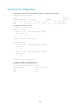
Configuring uplink interfaces
Uplink interfaces must be VFC interfaces in NP mode.
To configure an uplink interface:
Ste
p
Command
Remarks
1. Enter system view.
system-view N/A
2. Enter VFC interface view.
interface vfc interface-number
This interface is connected to the core
switch.
3. Configure the interface
to operate in NP mode.
fc mode np
By default, VFC interfaces of an NPV
switch operate in F mode.
Configuring downlink interfaces
Downlink interfaces must be FC or VFC interfaces in F mode.
To configure a downlink interface:
Ste
p
Command
Remarks
1. Enter system view.
system-view N/A
2. Enter VFC interface view.
interface vfc interface-number This interface is connected to a node.
3. Configure the interface to
operate in F mode.
fc mode f
By default, VFC interfaces of an NPV
switch operate in F mode.
Configuring downlink-to-uplink interface mappings
CAUTION:
If an uplink interface mapped by a downlink interface is not in the configured mappings, the switch
initializes the downlink interface, resulting in traffic interruption.
NPV switches automatically map downlink interfaces to uplink interfaces. When automatic mapping
cannot meet requirements, for example, when a downlink interface must be connected to a fabric
through a specified uplink interface, you can manually map the downlink interface to a specified uplink
interface or a set of uplink interfaces.
After you configure the mapping, the downlink interface can be mapped to only the configured uplink
interfaces. If none of the configured uplink interfaces is operational, the downlink interface cannot be
operational. A configured mapping selects the uplink interface with the minimum load from configured
uplink interfaces and then maps the downlink interface to it.
To configure uplink and downlink mapping:
Ste
p
Command
Remarks
1. Enter system view.
system-view
N/A
2. Enter VSAN view.
vsan vsan-id N/A