
R211x-HP Flexfabric 11900 FCoE Configuration Guide


99
Ste
p
Command
Remarks
3. Configure a
downlink-to-uplink
interface mapping.
npv traffic-map server-interface
interface-type interface-number
external-interface interface-type
interface-number
By default, no mapping is configured.
Initiating a disruptive load-balancing process
IMPORTANT:
This feature redistributes downlink traffic across all uplink interfaces for better load balancing, but it
causes traffic interruption.
If interfaces in a VSAN are not distributed evenly, you can use this feature to force all nodes in the VSAN
to relog in to the core switch.
To initiate a disruptive load-balancing process:
Ste
p
Command
1. Enter system view.
system-view
2. Enter VSAN view.
vsan vsan-id
3. Initiate a disruptive load-balancing process.
npv load-balance disruptive
Displaying and maintaining NPV
Execute display commands in any view.
Task Command
Display the nodes on downlink interfaces and their
mapped uplink interfaces.
display npv login [ vsan vsan-id ] [ interface
interface-type interface-number ]
display npv login [ vsan vsan-id ] count
Display the traffic mapping information.
display npv traffic-map [ vsan vsan-id ] [ interface
interface-type interface-number ]
Display status information. display npv status [ vsan vsan-id ]
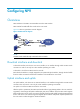
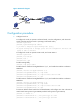
NPV configuration example
Network requirements
As shown in Figure 30, configure Switch A (edge switch) as an NPV switch to expand the network.