
R211x-HP Flexfabric 11900 FCoE Configuration Guide


92
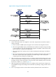
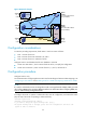
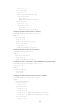
Figure 28 Network diagram
Configuration considerations
To meet the preceding requirements, divide VSAN 1 into three zones as follows:
• Zone 1 consists of Server A.
• Zone 2 consists of Server B and Disks A, B, and C.
• Zone 3 consists of Server C and Disks B and C.
Configure Switch A and distribute the full zone database to Switch B:
• Create zone alias Alias 1, which consists of Disks B and C, to simplify the configuration.
• Create zone set Zoneset 1, which consists of Zones 1, 2, and 3, and activate it.
Configuration procedure
Configure Switch A only.
For information about configuring Ethernet-to-VFC interface bindings and VLAN-to-VSAN mappings, see
"Configuring a VFC interface" and "Enabling FCoE for a VLAN and mapping a VSAN to the VLAN."
NOTE:
If a switch is connected to a server or storage device with a converged network adapter (CNA), you mus
t
also configure DCBX on the connecting Ethernet interface. For information about confi
g
urin
g
DCBX, see
Layer 2—LAN Switching Configuration Guide
.
# Configure the switch to operate in advanced mode, save the configuration, and reboot the switch.
(Skip this step if the switch is operating in advanced mode.)
<SwitchA> system-view
[SwitchA] system-working-mode advance
Do you want to change the system working mode? [Y/N]:y
The system working mode is changed, please save the configuration and reboot the
system to make it effective.
PWWN:
11:22:33:44:55:66:77:88
(FC_ID:020006)
FC_ID:
010001
FC_ID:
010002
FC_ID:
010003
FC_ID:
020004
PWWN:
22:33:44:55:66:77:88:99
(FC_ID:020005)
Switch A Switch B
Server A
Server B
Server C
Disk A
Disk B
Disk C
Zone 1
Zone 2
Zone 3
Alias 1