HP FlexFabric 11900 Switch Series Fundamentals Configuration Guide Part number: 5998-5255 Software version: Release 2111 and later Document version: 6W100-20140110
Legal and notice information © Copyright 2014 Hewlett-Packard Development Company, L.P. No part of this documentation may be reproduced or transmitted in any form or by any means without prior written consent of Hewlett-Packard Development Company, L.P. The information contained herein is subject to change without notice.
Contents Using the CLI ································································································································································ 1 CLI views ············································································································································································ 1 Entering system view from user view ·········································································································
Controlling user access ·············································································································································· 43 FIPS compliance ····························································································································································· 43 Controlling Telnet/SSH logins ······································································································································
Using the device as an FTP client ································································································································· 79 Establishing an FTP connection ···························································································································· 79 Managing directories on the FTP server ············································································································· 81 Working with files on the FTP serv
Upgrading software ················································································································································ 105 Overview······································································································································································· 105 Software types ·····················································································································································
Verifying software images··········································································································································· 148 Removing inactive software images ··························································································································· 148 Displaying and maintaining ISSU ······························································································································ 148 ISSU examples for
MDC configuration task list ········································································································································· 182 Creating an MDC ························································································································································ 183 Assigning hardware resources to an MDC ··············································································································· 183 Assigning an i
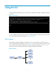
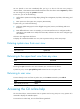
Using the CLI At the command-line interface (CLI), you can enter text commands to configure, manage, and monitor your device. Figure 1 CLI example You can use different methods to log in to the CLI, including through the console port, Telnet, and SSH. For more information about login methods, see "Login overview." CLI views Commands are grouped in different views by function. To use a command, you must enter its view. CLI views are hierarchically organized, as shown in Figure 2.
You are placed in user view immediately after you log in to the CLI. The user view prompt is , where Device-name indicates the device name. The device name is Sysname by default. You can change it by using the sysname command. In user view, you can do the following: • Perform basic operations including display, debug, file management, FTP, Telnet, clock setting, and reboot. • Enter system view. The system view prompt is [Device-name].
• Enter a question mark at a view prompt to display the first keyword of every command available in the view. For example: ? User view commands: archive Archive configuration backup Backup the startup configuration file to a TFTP server boot-loader Set boot loader … • Enter a space and a question mark after a command keyword to display all available, subsequent keywords and arguments.
For example, the info-center enable command enables the information center. The undo info-center enable command disables the information center. Entering a command When you enter a command, you can do the following: • Use keys or hotkeys to edit the command line. • Use abbreviated keywords or keyword aliases. Editing a command line To edit a command line, use the keys listed in Table 1 or the hotkeys listed in Table 2. When you are finished, you can press Enter to execute the command.
A specific argument might have more requirements. For more information, see the relevant command reference. To enter a printable character, you can enter the character or its ASCII code (in the range of 32 to 126). Abbreviating commands You can enter a command line quickly by entering incomplete keywords that uniquely identify the complete command. In user view, for example, commands starting with an s include startup saved-configuration and system-view.
Configuring and using command hotkeys The system defines the hotkeys shown in Table 2 and provides five configurable command hotkeys. Pressing a command hotkey is the same as entering a command. If a hotkey is also defined by the terminal software you are using to interact with the device, the terminal software definition takes effect. To configure a command hotkey: Step 1. Enter system view. Command Remarks system-view N/A By default: • Ctrl+G is assigned the display current-configuration command.
Hotkey Function Esc+F Moves the cursor forward one word. Esc+N Moves the cursor down one line. This hotkey is available before you press Enter. Esc+P Moves the cursor up one line. This hotkey is available before you press Enter. Esc+< Moves the cursor to the beginning of the clipboard. Esc+> Moves the cursor to the ending of the clipboard. Enabling redisplaying entered-but-not-submitted commands Your input might be interrupted by system information output.
Using the command history function The system automatically saves commands successfully executed by a login user to two command history buffers: • Command history buffer for the user line. • Command history buffer for all user lines. Table 4 Comparison between the two types of command history buffers Item Command history buffer for a user line Command history buffer for all user lines What kind of commands are stored in the buffer? Commands successfully executed by the current user of the user line.
Pausing between screens of output The system automatically pauses after displaying a screen if the output is too long to fit on one screen. You can use the keys described in "Output controlling keys" to display more information or stop the display. By default, up to 24 lines can be displayed on a screen. You can change the limit by using the screen-length screen-length command. For more information about this command, see Fundamentals Command Reference.
# Display information about VLAN 999, numbering each output line. display vlan 999 | by-linenum 1: VLAN ID: 999 2: VLAN type: Static 3: Route interface: Configured 4: IP address: 192.168.2.1 5: Subnet mask: 255.255.255.
Characters \N [] Meaning Examples Matches the preceding strings in parentheses, with the Nth string repeated once. Matches a single character in the brackets. "(string)\1" matches a string containing "stringstring". "(string1)(string2)\2" matches a string containing "string1string2string2". "(string1)(string2)\1\2" matches a string containing " string1string2string1string2". "[16A]" matches a string containing 1, 6, or A; "[1-36A]" matches a string containing 1, 2, 3, 6, or A (- is a hyphen).
Characters Meaning Examples \ Escape character. If a special character listed in this table follows \, the specific meaning of the character is removed. "\\" matches a string containing "\", "\^" matches a string containing "^", and "\\b" matches a string containing "\b". For example: # Use | begin line in the display current-configuration command to match the first line of output that contains line to the last line of output.
Use one of the following methods to save the output from a display command: • Save the output to a separate file. Use this method if you want to use one file for a single display command. • Append the output to the end of a file. Use this method if you want to use one file for multiple display commands. To save the output from a display command to a file, use one of the following commands in any view: Task Command Save the output from a display command to a separate file.
Untagged ports: Ten-GigabitEthernet1/0/1 Viewing and managing the output from a display command effectively You can use the following measures in combination to filter and manage the output from a display command: • Numbering each output line from a display command • Filtering the output from a display command • Saving the output from a display command to a file To use multiple measures to view and manage the output from a display command effectively, execute the following command in any view: Task
Login overview The first time you access the device, you can log in to the CLI of the default MDC through the console port. After login, you can create non-default MDCs, change console login parameters, or configure other access methods, including Telnet, SSH, modem, and SNMP. Non-default MDCs have no console port. To log in to a non-default MDC for the first time, you must log in to the default MDC and then switch to the non-default MDC using the switchto mdc command.
Login method Default settings and minimum configuration requirements By default, SNMP access is disabled. Accessing the device through SNMP To access the device through SNMP, complete the following configuration tasks: • Assign an IP address to a Layer 3 interface, and make sure the interface and the NMS can reach each other. • Configure SNMP basic parameters.
Logging in through the console port for the first device access The first time you access the device, you can only log in to the CLI through the console port. To log in through the console port, prepare a console terminal (for example, a PC) and make sure the console terminal has a terminal emulation program, for example, HyperTerminal in Windows XP. To log in through the console port: 1. Connect the DB-9 female connector of the console cable to the serial port of the PC. 2.
e. Select System Tools > Device Manager from the navigation tree. f. Select Ports (COM & LPT) from the right pane.
Figure 6 Setting the properties of the serial port 5. Power on the device and press Enter as prompted. Figure 7 Device CLI 6. At the default user view prompt , enter commands to configure the device or to view the running status of the device. To get help, enter ?.
Logging in to the CLI By default, you can log in to the CLI through the console port. After you log in, you can configure other login methods, including Telnet, SSH, and modem dial-in. To prevent illegal access to the CLI and control user behavior, you can configure login authentication, assign user roles, configure command authorization and command accounting, and use ACLs to filter unauthorized logins.
A relative number uniquely identifies a user line among all user lines that are the same type. The number format is user line type + number. Both the types of user lines are numbered starting from 0 and incrementing by 1. For example, the first VTY line is VTY 0. Login authentication modes You can configure login authentication to prevent illegal access to the device CLI. In non-FIPS mode, the device supports the following login authentication modes: • None—Disables authentication.
Telnet login is not supported in FIPS mode. Logging in through the console port locally You can connect a terminal to the console port of the device to log in and manage the device, as shown in Figure 8. For the login procedure, see "Logging in through the console port for the first device access." Figure 8 Logging in through the console port By default, console login is enabled and does not require authentication.
Step 3. Disable authentication. 4. Assign a user role. Command Remarks authentication-mode none By default, authentication is disabled for the AUX line. user-role role-name By default, an AUX line user of the default MDC is assigned the user role network-admin, and Non-default MDCs do not support console or AUX login. The next time you attempt to log in through the console port, you do not need to provide any username or password. Configuring password authentication for console login Step 1.
Configuring scheme authentication for console login Step Enter system view. 1. Command Remarks system-view N/A Use either command. A setting in user line view is applied only to the user line. A setting in user line class view is applied to all user lines of the class. • To enter AUX line view: Enter AUX line view or class view. 2. line aux first-number [ last-number ] • To enter AUX line class view: line class aux Enable scheme authentication. 3.
Step Command Remarks Use either command. A setting in user line view is applied only to the user line. A setting in user line class view is applied to all user lines of the class. • To enter AUX line view: 2. Enter AUX line view or class view. line aux first-number [ last-number ] • To enter AUX line class view: line class aux A non-default setting in either view takes precedence over a default setting in the other view.
Step Command Remarks By default, the terminal display type is ANSI. 10. Specify the terminal display type. terminal type { ansi | vt100 } 11. Set the maximum number of lines to be displayed on a screen. screen-length screen-length 12. Set the size of the command history buffer. history-command max-size value The device supports two terminal display types: ANSI and VT100. HP recommends that you set the display type to VT100 on both the device and the configuration terminal.
Task Remarks (Optional.) Setting the maximum number of concurrent Telnet users N/A (Optional.) Setting the DSCP value for outgoing Telnet packets N/A (Optional.) Configuring common VTY line settings N/A The Telnet login configuration is effective only for users who log in after the configuration is completed. Disabling authentication for Telnet login Step Command Remarks 1. Enter system view. system-view N/A 2. Enable Telnet server.
Figure 9 Telnetting to the device without authentication Configuring password authentication for Telnet login Step Command Remarks 1. Enter system view. system-view N/A 2. Enable Telnet server. telnet server enable By default, the Telnet server function is disabled. Use either command. A setting in user line view is applied only to the user line. A setting in user line class view is applied to all user lines of the class. • To enter VTY line view: 3. Enter VTY line view or class view.
Step Command Remarks By default, password authentication is enabled for VTY lines. In VTY line view, this command is associated with the protocol inbound command: 4. Enable password authentication. authentication-mode password • If the setting of either command is not the default in VTY line view, the setting of the other command in VTY line view takes effect. • If the settings of both commands are the defaults in VTY line view, the settings of the commands in VTY line class view take effect. 5.
Step Command Remarks Use either command. A setting in user line view is applied only to the user line. A setting in user line class view is applied to all user lines of the class. • To enter VTY line view: 3. Enter VTY line view or class view. line vty first-number [ last-number ] • To enter VTY line class view: line class vty A non-default setting in either view takes precedence over a default setting in the other view.
Figure 11 Scheme authentication interface for Telnet login Setting the maximum number of concurrent Telnet users Step 1. Enter system view. Command Remarks system-view N/A By default, the maximum number of concurrent Telnet users is 16. 2. Set the maximum number of concurrent Telnet users. aaa session-limit telnet max-sessions Changing this setting does not affect online users.
Typically, you configure the auto-execute command telnet X.X.X.X command on the device so the device redirects a Telnet user to the host at X.X.X.X. In this case, the connection to the current device is closed when the user terminates the Telnet connection to X.X.X.X. To configure common settings for VTY lines: Step 1. Enter system view. Command Remarks system-view N/A Use either command. • To enter VTY line view: 2. Enter VTY line view or class view.
Step Command Remarks By default, the session idle timeout is 10 minutes for all user lines. 9. Set the session idle timeout. idle-timeout minutes [ seconds ] If there is no interaction between the device and the user within the idle timeout, the system automatically terminates the user connection on the user line. If you set the idle timeout to 0, the session will not be aged out. 10. Specify a command to be automatically executed when users log in to the user lines.
Logging in through SSH SSH offers a secure method to remote login. By providing encryption and strong authentication, it protects devices against attacks such as IP spoofing and plain text password interception. For more information, see Security Configuration Guide. You can use an SSH client to log in to the device for remote management, or use the device as an SSH client to log in to an SSH server. By default, SSH login is disabled on the device.
Step Command Remarks Use either command. A setting in user line view is applied only to the user line. A setting in user line class view is applied to all user lines of the class. • To enter VTY line view: 5. Enter VTY line view or class view. line vty first-number [ last-number ] • To enter VTY line class view: line class vty A non-default setting in either view takes precedence over a default setting in the other view.
Step Command Remarks By default, the maximum number of concurrent SSH users is 16. 8. Set the maximum number of concurrent SSH users. aaa session-limit ssh max-sessions Changing this setting does not affect online users. If the current number of online SSH users is equal to or greater than the new setting, no additional SSH users can log in until the online users log out. For more information about this command, see Security Command Reference. 9. Exit to system view. 10. (Optional.
By default, modem dial-in is enabled, and does not require a username or password. After login, the user role network-admin is assigned. To use a pair of modems to remotely log in to the device: 1. Connect one modem to the serial port of the PC and another modem to the AUX port of the device. 2. Connect each modem to the PSTN through a telephone cable. 3. Obtain the telephone number of the device-side modem. 4.
Figure 15 Creating a connection Figure 16 Configuring the dialing parameters 7. Dial the telephone number to establish a connection to the device.
Figure 17 Dialing the number 8. After you hear the dial tone, press Enter as prompted: { { { If authentication is disabled, the user view prompt appears, as shown in Figure 18. If password authentication is enabled, the user view prompt appears after you provide the correct password. If password authentication is enabled, the user view prompt appears after you provide the correct username and password.
ATH command. The connection is terminated if OK is displayed. You can also terminate the connection by clicking in the HyperTerminal window. Displaying and maintaining CLI login Execute display commands in any view and the other commands in user view. Task Command Remarks Display online CLI user information. display users [ all ] N/A Display user line information.
Accessing the device through SNMP You can run SNMP on an NMS to access the device MIB and perform Get and Set operations to manage and monitor the device. Figure 19 SNMP access diagram Get/Set requests NMS Get/Set responses and Traps MIB Agent The device supports SNMPv1, SNMPv2c, and SNMPv3, and can work with various network management software products, including IMC. However, the device and the NMS must use the same SNMP version.
Step 5. Create an SNMPv3 user. Command Remarks snmp-agent usm-user v3 user-name group-name [ remote { ip-address | ipv6 ipv6-address } [ vpn-instance vpn-instance-name ] ] [ { cipher | simple } authentication-mode { md5 | sha } auth-password [ privacy-mode { aes128 | des56 } priv-password ] ] [ acl acl-number | acl ipv6 ipv6-acl-number ] * To send informs to an SNMPv3 NMS, you must use the remote ip-address option to specify the IP address of the NMS.
Controlling user access Use ACLs to prevent unauthorized access and configure command authorization and accounting to monitor and control user behavior. For more information about ACLs, see ACL and QoS Configuration Guide. FIPS compliance The device supports the FIPS mode that complies with NIST FIPS 140-2 requirements. Support for features, commands, and parameters might differ in FIPS mode and non-FIPS mode. For more information about FIPS mode, see Security Configuration Guide.
Configuration example Network requirements Configure the device in Figure 20 to permit only Telnet packets sourced from Host A and Host B. Figure 20 Network diagram Configuration procedure # Configure an ACL to permit packets sourced from Host A and Host B. system-view [Sysname] acl number 2000 match-order config [Sysname-acl-basic-2000] rule 1 permit source 10.110.100.52 0 [Sysname-acl-basic-2000] rule 2 permit source 10.110.100.
Step Command Remarks • SNMP community: snmp-agent community { read | write } [ simple | cipher ] community-name [ mib-view view-name ] [ acl acl-number | acl ipv6 ipv6-acl-number ] * • SNMPv1/v2c group: snmp-agent group { v1 | v2c } group-name [ read-view view-name ] [ write-view view-name ] [ notify-view view-name ] [ acl acl-number | acl ipv6 ipv6-acl-number ] * • SNMPv3 group: 2. Apply the ACL to an SNMP community, group, or user.
[Sysname-acl-basic-2000] rule 2 permit source 10.110.100.46 0 [Sysname-acl-basic-2000] quit # Associate the ACL with the SNMP community and the SNMP group. [Sysname] snmp-agent community read aaa acl 2000 [Sysname] snmp-agent group v2c groupa acl 2000 [Sysname] snmp-agent usm-user v2c usera groupa acl 2000 Configuring command authorization By default, commands are available for a user depending only on that user's user roles.
Step Command Remarks By default, authentication is disabled for the AUX line and password authentication is enabled for the VTY line. 3. Enable scheme authentication. In VTY line view, this command is associated with the protocol inbound command: authentication-mode scheme • If the setting of either command is not the default in VTY line view, the setting of the other command in VTY line view takes effect.
system-view [Device] telnet server enable # Enable scheme authentication for user lines VTY 0 through VTY 63. [Device] line vty 0 63 [Device-line-vty0-63] authentication-mode scheme # Enable command authorization for the user lines. [Device-line-vty0-63] command authorization [Device-line-vty0-63] quit # Configure an HWTACACS scheme that does the following: • Uses the HWTACACS server at 192.168.2.20:49 for authentication and authorization.
This section provides only the procedure for configuring command accounting. To make the command accounting function take effect, you must configure a command accounting method in ISP domain view. For more information, see Security Configuration Guide. Configuration procedure To configure command accounting: Step 1. Enter system view. Command Remarks system-view N/A Use either command. A setting in user line view is applied only to the user line.
Configuration example Network requirements To monitor and control user operations on the device in Figure 23, configure the device to send commands executed by users to the HWTACACS server. Figure 23 Network diagram Configuration procedure # Enable the Telnet server. system-view [Device] telnet server enable # Enable command accounting for user line AUX 0.
[Device-hwtacacs-tac] user-name-format without-domain [Device-hwtacacs-tac] quit # Configure the system-predefined domain system to use the HWTACACS scheme for command accounting.
Configuring RBAC Role based access control (RBAC) controls user access to commands and resources based on user role. This chapter describes the basic idea of RBAC and guides you through the RBAC configuration procedure. Overview On devices that support multiple users, RBAC is used to assign command and resource access permissions to user roles that are created for different job functions. Users are given permission to access a set of commands and resources based on their user roles.
A user role can access the set of permitted commands specified in its rules. The user role rules include predefined (identified by sys-n) and user-defined user role rules. • If two user-defined rules of the same type conflict, the one with the higher ID takes effect. For example, if rule 1 permits the ping command, rule 2 permits the tracert command, and rule 3 denies the ping command, the user role can use the tracert command but not the ping command.
User role name Permissions mdc-admin Accesses all the features and resources in the administered MDC, except for the display security-logfile summary, info-center security-logfile directory, and security-logfile save commands. • Accesses the display commands for all the features and resources mdc-operator available in the administered MDC, except for commands such as display history-command all and display security-logfile summary.
Assigning user roles You assign access rights to users by assigning at least one user role. The users can use the collection of commands and resources accessible to any user role assigned to them. For example, you can access any interface to use the qos apply policy command if you are assigned the following user roles: • User role A denies access to the qos apply policy command and permits access to only interface Ten-GigabitEthernet 1/0/1.
Creating user roles In addition to the predefined user roles, you can create up to 64 custom user roles for granular access control. To create a user role: Step 1. Enter system view. Command Remarks system-view N/A 2. Create a user role and enter user role view. role name role-name By default, the system has 21 predefined user roles: network-admin, network-operator, mdc-admin, mdc-operator, level-n (where n equals an integer in the range 0 to 15), and security-audit.
Step Command Remarks Configure at least one command. • Configure a command rule: By default, a user-defined user role has no rules or access to any command. • Configure a feature rule: Repeat this step to add up to 256 rules to the user role. rule number { deny | permit } command command-string 3. rule number { deny | permit } { execute | read | write } * feature [ feature-name ] Configure a rule.
Changing the interface policy of a user role Step Command Remarks 1. Enter system view. system-view N/A 2. Enter user role view. role name role-name N/A interface policy deny By default, the interface policies of user roles permit access to all interfaces. 3. 4. Enter user role interface policy view. (Optional.) Specify a list of interfaces accessible to the user role. This command disables the access of the user role to any interface.
Assigning user roles To control user access to the system, you must assign at least one user role. Make sure at least one user role among the user roles assigned by the server exists on the device. User role assignment procedure varies with remote AAA authentication users, local AAA authentication users, and non-AAA authentication users (see "Assigning user roles"). For more information about AAA authentication, see Security Configuration Guide.
Assigning user roles to local AAA authentication users Configure user roles for local AAA authentication users in their local user accounts. Every local user has a default user role. If this default user role is not suitable, delete it. If a local user is the only one with the security-audit user role, this local user cannot be deleted. The security-audit user role is mutually exclusive with other user roles.
Step Command Remarks • To enter user line view: 2. line { first-num1 [ last-num1 ] | { aux | vty } first-num2 [ last-num2 ] } Enter user line view or user line class view. • To enter user line class view: line class { aux | vty } For information about the priority order and application scope of the configurations in user line view and user line class view, see "Logging into the CLI." Repeat this step to specify up to 64 user roles on a user line.
{ If RADIUS authentication is used, you must create a user account for each level-n user role in the $enabn$ format or the $enabn$@domain-name format, where n represents the user role level. When you use this method, the username you enter is ignored. You can pass authentication as long as the password is correct. If you execute the quit command after obtaining user role authorization, you are logged out of the device.
Step Command Remarks Use this step for local password authentication. 3. Set a local authentication password for a user role. • In non-FIPS mode: By default, no password is configured. • In FIPS mode: If you log in to the default MDC and do not specify a user role for the command, the command sets a password for the user role network-admin. If you log in to a non-default MDC and do not specify a user role for the command, the command sets a password for the user role mdc-admin.
RBAC configuration examples RBAC configuration example for local AAA authentication users Network requirements The switch in Figure 24 performs local AAA authentication for the Telnet user at 192.168.1.58. This Telnet user has the username user1@bbb and is assigned the user role role1. Configure role1 to have the following permissions: • Executes the read commands of any feature. • Configures no VLANs except VLANs 10 to 20.
[Switch-role-role1] vlan policy deny [Switch-role-role1-vlanpolicy] permit vlan 10 to 20 [Switch-role-role1-vlanpolicy] quit [Switch-role-role1] quit # Create a device management user named user1 and enter its view. [Switch] local-user user1 class manage # Set a plaintext password aabbcc for the user. [Switch-luser-manage-user1] password simple aabbcc # Set the service type to Telnet. [Switch-luser-manage-user1] service-type telnet # Assign role1 to the user.
• Performs read and write commands of the features arp and radius. • Has no access to read commands of the feature acl. • Configures VLANs 1 to 20 and interfaces Ten-GigabitEthernet 1/0/1 to Ten-GigabitEthernet 1/0/24. The switch and the FreeRADIUS server use the shared key expert and authentication port 1812. The switch delivers usernames with their domain names to the server. Figure 25 Network diagram Configuration procedure Make sure the settings on the switch and the RADIUS server match. 1.
IMPORTANT: Because RADIUS user authorization information is piggybacked in authentication responses, the authentication and authorization methods must use the same RADIUS scheme. [Switch] domain bbb [Switch-isp-bbb] authentication login radius-scheme rad [Switch-isp-bbb] authorization login radius-scheme rad [Switch-isp-bbb] quit # Create the feature group fgroup1. [Switch] role feature-group name fgroup1 # Add the features arp and radius to the feature group.
# Configure the settings required for the FreeRADIUS server to communicate with the switch. (Details not shown.) Verifying the configuration # Telnet to the switch, and enter the username and password to access the switch. (Details not shown.) # Verify that you can use all commands available in ISP view. system-view [Switch] domain abc [Switch-isp-abc] authentication login radius-scheme abc [Switch-isp-abc] quit # Verify that you can use all read and write commands of the features radius and arp.
Figure 26 Network diagram Configuration procedure 1. Configure the switch: # Assign an IP address to VLAN-interface 2, the interface connected to the Telnet user. system-view [Switch] interface vlan-interface 2 [Switch-Vlan-interface2] ip address 192.168.1.70 255.255.255.0 [Switch-Vlan-interface2] quit # Assign an IP address to VLAN-interface 3, the interface connected to the HWTACACS server. [Switch] interface vlan-interface 3 [Switch-Vlan-interface3] ip address 10.1.1.2 255.255.255.
# Configure ISP domain bbb to use local authorization for login users. [Switch-isp-bbb] authorization login local # Apply the HWTACACS scheme hwtac to the ISP domain. [Switch-isp-bbb] authentication super hwtacacs-scheme hwtac [Switch-isp-bbb] quit # Create a device management user named test and enter its view. Set the service type to Telnet, and set the password to aabbcc.
Figure 27 Configuring advanced TACACS+ settings Verifying the configuration 1. Telnet to the switch, and enter the username test@bbb and password aabbcc to access the switch. Verify that you have access to diagnostic commands. telnet 192.168.1.70 Trying 192.168.1.70 ... Press CTRL+K to abort Connected to 192.168.1.59 ... ****************************************************************************** * Copyright (c) 2010-2013 Hewlett-Packard Development Company, L.P.
ssh2 Establish a secure shell client connection super Switch to a user role system-view Enter the System View telnet Establish a telnet connection tracert Tracert function 2. Obtain the level-3 user role: # Use the super password to obtain the level-3 user role. When the system prompts for a username and password, enter the username test@bbb and password enabpass.
Login attempts by RADIUS users always fail Symptom Attempts by a RADIUS user to log in to the network access device always fail, even though the network access device and the RADIUS server can communicate with one another and all AAA settings are correct. Analysis RBAC requires that a login user have at least one user role. If the RADIUS server does not authorize the login user to use any user role, the user cannot log in to the device.
Configuring FTP File Transfer Protocol (FTP) is an application layer protocol based on the client/server model. It is used to transfer files from one host to another over an IP network. FTP server uses TCP port 20 to transfer data and TCP port 21 to transfer control commands. For more information about FTP, see RFC 959. FTP supports the following transfer modes: • Binary mode—Used to transfer image files, such as .app, .bin, and .btm files. • ASCII mode—Used to transfer text files, such as .txt, .
Configuring basic parameters Step Command Remarks 1. Enter system view. system-view N/A 2. Enable the FTP server. ftp server enable By default, the FTP server is disabled. 3. (Optional.) Use an ACL to control access to the FTP server. ftp server acl { acl-number | ipv6 acl-number6 } By default, no ACL is used for access control. The default idle-timeout interval is 30 minutes. 4. (Optional.) Configure the idle-timeout interval.
Remote authorization—A remote authorization server assigns authorized directories on the device to FTP clients. • For information about configuring authentication and authorization, see Security Configuration Guide. Manually releasing FTP connections Task Command • Release the FTP connection established using a specific user Manually release FTP connections.
[Sysname] local-user abc class manage [Sysname-luser-abc] password simple 123456 [Sysname-luser-abc] authorization-attribute user-role network-admin work-directory flash:/ [Sysname-luser-abc] service-type ftp [Sysname-luser-abc] quit NOTE: If the password control feature is configured, the password must meet the password requirements defined by the feature. For more information, see Security Configuration Guide. # Enable the FTP server.
ftp> put temp.bin # Exit FTP. ftp> bye FTP server configuration example in IRF mode Network requirements An IRF fabric that has two member devices acts as the FTP server. On each member, the active and standby MPUs reside in slot 4 and slot 5, respectively. Create a local user account with username abc and password 123456 on the FTP server. Use the user account to log in to the FTP server from the FTP client, upload the file temp.
[Sysname] ftp server enable [Sysname] quit 3. Perform FTP operations from the FTP client: # Log in to the FTP server at 1.1.1.1 using the username abc and password 123456. c:\> ftp 1.1.1.1 Connected to 1.1.1.1. 220 FTP service ready. User(1.1.1.1:(none)):abc 331 Password required for abc. Password: 230 User logged in. # Use the ASCII mode to download the configuration file config.cfg from the server to the client for backup. ftp> ascii 200 TYPE is now ASCII ftp> get config.cfg back-config.
Step Command Remarks • (Method 1) Log in to the FTP server 4. directly in user view: ftp [ ftp-server [ service-port ] [ vpn-instance vpn-instance-name ] [ dscp dscp-value | source { interface interface-type interface-number | ip source-ip-address } ] ] * Log in to the FTP server. • (Method 2) Log in to the FTP server in FTP client view: a. ftp Use either method. The source IP address specified in the ftp command takes precedence over the one set by the ftp client source command. b.
Managing directories on the FTP server Task Command • Display the detailed information of a directory or Display directory and file information on the FTP server. file on the FTP server: dir [ remotefile [ localfile ] ] • Display the name of a directory or file on the FTP server: ls [ remotefile [ localfile ] ] Change the working directory on the FTP server. cd { directory | .. | / } Return to the upper level directory on the FTP server. cdup Display the working directory that is being accessed.
Task Command Remarks Set the file transfer mode to binary. binary The default transfer mode is ASCII in versions prior to Release 2111, and binary in Release 2111 and later. Set the FTP operation mode to passive. passive The default mode is passive. Display or change the local working directory of the FTP client. lcd [ directory | / ] N/A Upload a file to the FTP server. put localfile [ remotefile ] N/A Download a file from the FTP server.
Task Command Remarks Display FTP connection status. status N/A Display the system information of the FTP server. system N/A Enable or disable FTP operation information display. verbose By default, this function is enabled. Enable or disable FTP client debugging. debug By default, FTP client debugging is disabled. Clear the reply information in the buffer.
• Log in to the FTP server from the FTP client using the user account with username abc and password 123456 (which has been created on the PC). • Download the file temp.bin from the PC to the device, and upload the configuration file startup.cfg from the device to the PC for backup. Figure 31 Network diagram Configuration procedure # Configure IP addresses as shown in Figure 31 and make sure the device and PC can reach each other. (Details not shown.) # Examine the storage space of the device.
ftp> put startup.cfg back-startup.cfg local: startup.cfg remote: back-startup.cfg 150 Connecting to port 47461 226 File successfully transferred 3494 bytes sent in 5.646 seconds (618.00 kbyte/s) ftp> bye 221-Goodbye. You uploaded 2 and downloaded 2 kbytes. 221 Logout. FTP client configuration example in IRF mode Network requirements • Use the IRF fabric that has two member devices as the FTP client and the PC as the FTP server.
The message "200 Type is Image (Binary)" appears only in Release 2111 or later. # Set the file transfer mode to binary. This step is required in a version prior to Release 2111. In Release 2111 or later, the default mode is binary. ftp> binary 200 TYPE is now 8-bit binary # Download the file temp.bin from the PC to the Flash root directory of the global active MPU. ftp> get temp.bin local: temp.bin remote: temp.
Configuring TFTP Trivial File Transfer Protocol (TFTP) is a simplified version of FTP for file transfer over secure reliable networks. TFTP uses UDP port 69 for data transmission. In contrast to TCP-based FTP, TFTP does not require authentication or complex message exchanges, and is easier to deploy. TFTP is suited for reliable network environments. The device can only operate as a TFTP client. You can upload a file from the device to the TFTP server or download a file from the TFTP server to the device.
Step 5. Command Download or upload a file in an IPv4 network. Remarks tftp tftp-server { get | put | sget } source-filename [ destination-filename ] [ vpn-instance vpn-instance-name ] [ dscp dscp-value | source { interface interface-type interface-number | ip source-ip-address } ] * The source IP address specified in this command takes precedence over the one set by the tftp client source command. Use this command in user view. Configuring the device as an IPv6 TFTP client Step Command Remarks 1.
Managing the file system This chapter describes how to manage the device's file system, including the storage media, directories, and files. IMPORTANT: • Before managing storage media, files, and directories, make sure you know the possible impacts. • A file or directory whose name starts with a period (.) is considered a hidden file or directory. Do not give a common file or directory a name that starts with a period. • Some system files and directories are hidden.
Format Description Example Specifies a file in a specific storage medium. The drive argument represents the storage medium name. The storage medium on the active MPU is typically flash. drive:/[path]/file-name The storage medium on the standby MPU is typically slotn#flash, where n represents the number of the slot that hosts the standby MPU, for example, slot16#flash. To view the correspondence between an MPU and its slot number, use the display device command. • flash:/test/a.
Managing files CAUTION: To avoid file system corruption: • In standalone mode, do not install or remove storage media or perform active/standby switchover during file operations. • In IRF mode, do not install or remove storage media or perform a switchover between the active MPU of the IRF fabric and the standby MPU of the IRF fabric during file operations. You can perform the following file management tasks: • Display directory and file information. • Display file contents.
Copying a file Perform this task in user view. Task Command Copy a file. copy fileurl-source fileurl-dest Moving a file Perform this task in user view. Task Command Move a file. move fileurl-source fileurl-dest Compressing/decompressing a file Perform the following tasks in user view: Task Command Compress a file. gzip filename Decompress a file. gunzip filename Archiving/extracting files Perform the following tasks in user view: Task Command Archive files.
Task Command Delete a file by moving it to the recycle bin. delete file-url Restore a file from the recycle bin. undelete file-url Delete a file permanently. delete /unreserved file-url IMPORTANT: Do not use the delete command to delete files from the recycle bin. To delete files from the recycle bin, use the reset recycle-bin command. Deleting files from the recycle bin The device supports multiple storage media. Each storage medium has a recycle bin of its own. A recycle bin is a folder named .
• Create or remove a directory. • Display or change the current working directory. • Display a specific directory. Displaying directory information Perform this task in user view. Task Command Display directory or file information. dir [ /all ] [ file-url | /all-filesystems ] Displaying the current working directory Perform this task in user view. Task Command Display the current working directory. pwd Changing the current working directory Perform this task in user view.
Managing storage media CAUTION: To avoid file system corruption: • In standalone mode, do not install or remove storage media or cards or perform active/standby switchover while the system is repairing or formatting a storage medium. • In IRF mode, do not install or remove storage media or perform a switchover between the active MPU of the IRF fabric and a standby MPU of the IRF fabric while the system is repairing or formatting a storage medium.
Setting the operation mode for files and folders The device supports the following file and folder operation modes: • alert—The system prompts for confirmation when your operation might cause problems such as file corruption and data loss. This mode provides an opportunity to cancel a disruptive operation. • quiet—The system does not prompt for confirmation. To set the operation mode for files and folders: Step Command Remarks 1. Enter system view. system-view N/A 2.
Managing configuration files You can use the CLI or the BootWare menus to manage configuration files. This chapter explains how to manage configuration files from the CLI. Overview A configuration file saves a set of commands for configuring software features on the device. You can save any configuration to a configuration file so they can survive a reboot. You can also back up configuration files to a host for future use.
Figure 34 Configuration loading process during startup Start BootWare runs Enter BootWare menus? Yes No No No Main configuration file available? Backup configuration file available? Yes Yes Select "Skip Current System Configuration" Load initial settings Load backup configuration file Load main configuration file Load initial settings Software runs with initial settings Software runs with settings in backup file Software runs with settings in main file Software runs with initial settings End
Startup configuration file selection At startup, the device uses the following procedure to identify the configuration file to load: 1. The device searches for a valid .cfg next-startup configuration file. 2. If one is found, the device searches for an .mdb file that has the same name and content as the .cfg file. 3. If an .mdb file has the same name and content as the .cfg file, the device starts up with the .mdb file. If none is found, the device starts up with the .cfg file.
Enabling configuration encryption Configuration encryption enables the device to encrypt a startup configuration file automatically when saving the running configuration. This function provides the following methods: • Private key method—Any HP device running Comware V7 software can decrypt the encrypted configuration file. • Public key method—Any HP device can decrypt the encrypted configuration file. To enable configuration encryption: Step Command Remarks 1. Enter system view.
Task Save the running configuration to a configuration file in the root directory of each MPU's flash memory and specify the file as the startup configuration file. Command Remarks If you execute the save [ safely ] command without specifying any other keyword, the command saves the configuration to the main startup configuration file for the MDC where you are logged in.
Task Command Remarks By default, no configuration file is specified for the next startup. Specify the next-startup configuration file. startup saved-configuration cfgfile [ backup | main ] Use the display startup command and the display saved-configuration command in any view to verify the configuration.
Step 1. Restore the main next-startup configuration file from a TFTP server in user view. 2. (Optional.) Verify that the specified configuration file has been set as the main next-startup configuration file. Command Remarks restore startup-configuration from src-addr src-filename This command is not supported in FIPS mode.
Task Command Display the contents of the configuration file for the next system startup. display saved-configuration Display names of the configuration files used at this startup and the next startup. display startup Display the valid configuration in the current view.
Upgrading software This chapter describes types of software and how to upgrade software from the CLI. For a comparison of all software upgrade methods, see "Upgrade methods." Overview Software upgrade enables you to have new features and fix bugs. Before performing an upgrade, use the release notes for the new software version to verify software and hardware compatibility and evaluate upgrade impacts. Software types The following software types are available: • BootWare image—A .
Comware image redundancy and loading procedure You can specify two sets of Comware software images: one main and one backup. The system always attempts to start up with the main images. If any main image does not exist or is invalid, the system tries the backup images. Figure 35 shows the entire Comware image loading procedure. This procedure assumes that the main image set and the backup image set have feature images and patch images.
Figure 36 System startup process Upgrade methods Upgrading method Software types Upgrading from the CLI • BootWare image • Comware images (excluding patches) Remarks This method is disruptive. You must reboot the entire device to complete the upgrade. Use this method when the device cannot start up correctly. Upgrading from the BootWare menus • BootWare image • Comware software images IMPORTANT: Upgrade an IRF fabric from the CLI rather than the BooWare menus.
If you skip this task, the device upgrades the BootWare automatically when it upgrades the startup software images. The BootWare image preloaded into the BootWare does not affect the device running status. 3. Specify the image file as the startup software image file. 4. If you are upgrading a standalone device, reboot the device. If you are upgrading an IRF fabric, reboot the entire IRF fabric. 5. Verify the upgrade. Preparing for the upgrade 1.
Step Command • In standalone mode: 4. (Optional.) Back up the current BootWare image in the Normal area of BootWare to the Backup area. bootrom backup slot slot-number-list • In IRF mode: bootrom backup chassis chassis-number slot slot-number-list Remarks Use one of the commands to back up the BootWare image for a future version rollback or image restoration, depending on the backup location and device operating mode. • In standalone mode: 5.
Step Command Remarks When you use method 3, make sure you understand the following requirements and upgrade results: • If the active MPU started up with • Method 1: boot-loader file ipe-filename slot slot-number { backup | main } • Method 2: 2. Specify main or backup startup images for the standby MPU.
Step Command Remarks Upgrade files must be saved in the root directory of the storage medium on the global active MPU. • Method 1: boot-loader file ipe-filename chassis chassis-number slot slot-number { backup | main } 1. Specify main or backup startup image files for the global active MPU.
Restoring or downgrading the BootWare image To restore or downgrade the BootWare image for a card, make sure you have used the bootrom backup command or the bootrom read command to back up the image to the Backup area of BootWare or the storage media. Before performing a downgrade, also verify software compatibility.
1. Copies the current software images of the active MPU. 2. Specifies them as startup software images. 3. Reboots with these images. IMPORTANT: To ensure a successful synchronization in a multi-user environment, prevent users from rebooting or swapping MPUs during the software synchronization process. You can configure the information center to output the synchronization status to configuration terminals (see Network Management and Monitoring Configuration Guide).
Figure 37 Network diagram TFTP server TFTP client 1.1.1.1/24 2.2.2.2/24 Internet Device Configuration procedure # Configure IP addresses and routes to make sure the device and the TFTP server can reach each other. (Details not shown.) # Complete TFTP settings on both the device and the TFTP server. (Details not shown.) # Display information about the current software images. display version # Use TFTP to download the image file 11900.
Figure 38 Network diagram Master (Member ID = 1) Internet Subordinate (Member ID = 2) IRF link IRF 1.1.1.1/24 2.2.2.2/24 TFTP server Configuration procedure # Configure IP addresses and routes to make sure the device and the TFTP server can reach each other. (Details not shown.) # Complete TFTP settings on both the device and the TFTP server. (Details not shown.) # Display information about the current software images. display version # Use TFTP to download the image file 11900.
ISSU overview The In-Service Software Upgrade (ISSU) function enables software upgrade with the least amount of downtime. ISSU is implemented on the basis of the following design advantages: • Separation of service features from basic functions. The Comware software is packaged into multiple images. Boot and system images provide the basic functionality and service features. Feature images provide advanced features. Patch images fix software bug.
ISSU method Application scenario ISSU method indicated by the display version comp-matrix file command Incompatible upgrade Upgrade to an incompatible version Incompatible upgrade ISSU methods for a compatible version The following are ISSU methods for a compatible version: • Incremental upgrade: An incremental upgrade analyzes the differences between the new and old software versions and upgrades only the different parts.
switching fabric card upgrade when the device has multiple switching fabric cards that support this method. ISSU method for an incompatible version Only one method is available for an ISSU to an incompatible version: incompatible upgrade. This method reboots the device to load the new software. To reduce service interruption during the upgrade, implement hardware redundancy. ISSU command series The switch provides two series of commands for ISSU: install series and issu series.
ISSU prerequisites • Read the software release notes to determine which software images need to be upgraded, whether these software images are compatible with one another, and whether these software images are compatible with the software images running on the device. Then, based on the compatibility, determine the command series to use. • Use the display device command to verify that the system is operating correctly. If there are any problems, remove the problems before performing an ISSU.
At reboot, a subordinate device automatically synchronizes the master device's configuration and status data. This process takes time. You must wait for the synchronization to complete before using the issu load command on the subordinate device. To verify that the synchronization has completed successfully, do the following: { { { Use the display device command to verify that all cards of the subordinate device are in normal state. Use the display mdc command to verify that all MDCs are in active state.
Performing an ISSU by using issu series commands Performing an ISSU in standalone mode When you use the issu series commands to install or upgrade the software of MPUs, the device automatically install or upgrade the software of the service cards and switching fabric cards as needed. You do not need to install or upgrade the software of the service cards and switching fabric cards separately. The ISSU procedure varies depending on whether the device has a single or two MPUs.
Step 5. 6. Command Remarks Perform an active/standby switchover and upgrade the service cards and switching fabric cards. issu run switchover N/A (Optional.) Accept the upgrade and delete the automatic-rollback timer. issu accept N/A • To upgrade the original active 7. Complete the ISSU process or roll back to the original software configuration.
on the Version compatibility list and the value of the Upgrade Way field is Service Upgrade or File Upgrade, the new and old images are compatible and an incremental upgrade applies. To perform an incremental upgrade to a compatible version, execute the following commands in user view: Step 1. Command Upgrade the MPU and configure the upgrade images as the main startup software images for the MPU.
Performing an ISSU for a multichassis IRF fabric ISSU for a multichassis IRF fabric should be performed as per member in two steps: first upgrade a subordinate member, and then upgrade the master and the other subordinate members.
To perform an ISSU for an incompatible version, execute the following commands in user view: Step Command Upgrade subordinate members and configure the upgrade images as the main startup software images for the subordinate members. 1.
Step Command Remarks By default, the automatic-rollback interval is 45 minutes. 2. 3. (Optional.) Set the automatic rollback timer. issu rollback-timer minutes Return to user view. quit This timer starts when you execute the issu run switchover command. If you do not execute the issu accept or issu commit command before this timer expires, the system automatically rolls back to the original software configuration. N/A • Method 1: 4. 5. 6. 7.
Step 1. Command Upgrade the global standby MPU and configure the upgrade images as the startup software images for the MPU. Remarks • Method 1: issu load file { boot filename | system filename | feature filename&<1-30> } * chassis chassis-number slot slot-number • issu load file ipe ipe-filename chassis chassis-number slot slot-number • To upgrade the original global active 2. Complete the ISSU process or roll back to the original software configuration.
Step Command • To complete the ISSU process: 2. Complete the ISSU process or roll back to the original software configuration. issu commit chassis chassis-number slot slot-number • To roll back to the original software configuration: issu rollback Remarks Specify the member ID and slot number of the only MPU for the chassis chassis-number slot slot-number option. After the issu commit command is completed, the ISSU process ends and the ISSU status changes to Init.
Task Command Display the software images included in an .ipe file. display install ipe-info ipe-filename Display ongoing ISSU activate, deactivate, and rollback operations. display install job Display ISSU logs. display install log [ verbose ] Display software image file information. display install package { filename | all } [ verbose ] Display rollback point information. display install rollback [ point-id ] Display all software image files that include a specific component or file.
Task Command Display all software image files that include a specific component or file. display install which [ chassis chassis-number slot slot-number] { component name | file filename } Display automatic-rollback timer information. display issu rollback-timer Display ISSU status information. display issu state Display version compatibility information. display version comp-matrix Clear ISSU logs. reset install log-history oldest log-number Clear ISSU rollback points.
flash:/boot-r2110.bin flash:/system-r2110.bin flash:/feature1-r2110.bin # Identify the ISSU method and possible impacts of the upgrade on the device. display version comp-matrix file feature flash:/feature1-r2111.bin Feature image: flash:/feature1-r2111.
issu commit slot 4 Upgrade summary according to following table: flash:/feature1-r2111.bin Running Version New Version Release 2110 Release 2111 Slot Upgrade Way 4 Service Upgrade Upgrading software images to compatible versions. Continue? [Y/N]: y # Verify that both MPUs are running the new image. display install active Active packages on slot 4: flash:/boot-r2110.bin flash:/system-r2110.bin flash:/feature1-r2111.bin Active packages on slot 5: flash:/boot-r2110.
flash:/boot-r2110.bin flash:/system-r2110.bin flash:/feature1-r2110.bin # Identify the ISSU method and possible impacts of the upgrade on the device. display version comp-matrix file feature flash:/feature1-r2111.bin Feature image: flash:/feature1-r2111.bin Version: V700R001B45D002 Version Compatibility List: V700R001B45D002 Version Dependency System List: V700R001B45D001 V700R001B45D002 incompatible upgrade. The output shows that the two versions are incompatible.
Feature rollback example Rollback requirement As shown in Figure 41, the device has two MPUs: one in slot 4 (active MPU) and the other in slot 5 (standby MPU). R2111 and R2110 are compatible. Roll back the feature1 feature from R2111 to R2110 after upgrading it from R2110 to R2111. Figure 41 Network diagram Rollback procedure # Download the upgrade image from the TFTP server. tftp 2.2.2.2 get feature1-r2111.
flash:/feature1-r2111.bin feature1 Influenced service according to following table on slot 5: flash:/feature1-r2111.bin feature1 The output shows that an incremental upgrade is recommended and the feature1 feature module will be rebooted during the upgrade process. # Upgrade feature1 on the standby MPU. issu load file feature flash:/feature1-r2111.bin slot 5 This operation will delete the rollback point information for the previous upgrade and maybe get unsaved configuration lost.
# Verify that both MPUs are running the old image. Active packages on slot 4: flash:/boot-r2110.bin flash:/system-r2110.bin flash:/feature1-r2110.bin Active packages on slot 5: flash:/boot-r2110.bin flash:/system-r2110.bin flash:/feature1-r2110.bin ISSU examples for using issu series commands in IRF mode Feature upgrade to a compatible version Upgrade requirement As shown in Figure 42, each member in the IRF fabric has one MPU in slot 4 (the active MPU) and one MPU in slot 5 (the standby MPU).
flash:/feature1-r2110.bin Active packages on chassis 1 slot 5: flash:/boot-r2110.bin flash:/system-r2110.bin flash:/feature1-r2110.bin Active packages on chassis 2 slot 4: flash:/boot-r2110.bin flash:/system-r2110.bin flash:/feature1-r2110.bin Active packages on chassis 2 slot 5: flash:/boot-r2110.bin flash:/system-r2110.bin flash:/feature1-r2110.bin # Identify the ISSU method and possible impacts of the upgrade on the IRF fabric. display version comp-matrix file feature flash:/feature1-r2111.
This operation will delete the rollback point information for the previous upgrade and maybe get unsaved configuration lost. Continue? [Y/N]:y Upgrade summary according to following table: flash:/feature1-r2111.bin Running Version New Version Release 2110 Release 2111 Chassis Slot Upgrade Way 2 4 Service Upgrade 2 5 Service Upgrade Upgrading software images to compatible versions. Continue? [Y/N]: y # Perform a master/subordinate switchover.
flash:/system-r2110.bin flash:/feature1-r2111.bin Active packages on chassis 2 slot 5: flash:/boot-r2110.bin flash:/system-r2110.bin flash:/feature1-r2111.bin Feature upgrade to an incompatible version Upgrade requirement As shown in Figure 43, each member in the IRF fabric has one MPU in slot 4 (the active MPU) and one MPU in slot 5 (the standby MPU). Upgrade the feature1 feature from R2110 to R2111. The two versions are ISSU-incompatible versions.
flash:/feature1-r2110.bin Active packages on chassis 2 slot 5: flash:/boot-r2110.bin flash:/system-r2110.bin flash:/feature1-r2110.bin # Identify the ISSU method and possible impacts of the upgrade on the IRF fabric. display version comp-matrix file feature flash:/feature1-r2111.bin Feature image: flash:/feature1-r2111.
flash:/boot-r2110.bin flash:/system-r2110.bin flash:/feature1-r2111.bin Active packages on chassis 1 slot 5: flash:/boot-r2110.bin flash:/system-r2110.bin flash:/feature1-r2111.bin Active packages on chassis 2 slot 4: flash:/boot-r2110.bin flash:/system-r2110.bin flash:/feature1-r2111.bin Active packages on chassis 2 slot 5: flash:/boot-r2110.bin flash:/system-r2110.bin flash:/feature1-r2111.
flash:/system-r2110.bin flash:/feature1-r2110.bin Active packages on chassis 1 slot 5: flash:/boot-r2110.bin flash:/system-r2110.bin flash:/feature1-r2110.bin Active packages on chassis 2 slot 4: flash:/boot-r2110.bin flash:/system-r2110.bin flash:/feature1-r2110.bin Active packages on chassis 2 slot 5: flash:/boot-r2110.bin flash:/system-r2110.bin flash:/feature1-r2110.bin # Identify the ISSU method and possible impacts of the upgrade on the IRF fabric.
issu load file feature flash:/feature1-r2111.bin chassis 2 This operation will delete the rollback point information for the previous upgrade and maybe get unsaved configuration lost. Continue? [Y/N]:y Upgrade summary according to following table: flash:/feature1-r2111.bin Running Version New Version Release 2110 Release 2111 Chassis Slot Upgrade Way 2 4 Service Upgrade 2 5 Service Upgrade Upgrading software images to compatible versions.
display install active Active packages on chassis 1 slot 4: flash:/boot-r2110.bin flash:/system-r2110.bin flash:/feature1-r2110.bin Active packages on chassis 1 slot 5: flash:/boot-r2110.bin flash:/system-r2110.bin flash:/feature1-r2110.bin Active packages on chassis 2 slot 4: flash:/boot-r2110.bin flash:/system-r2110.bin flash:/feature1-r2110.bin Active packages on chassis 2 slot 5: flash:/boot-r2110.bin flash:/system-r2110.bin flash:/feature1-r2110.
Performing an ISSU by using install series commands Performing an ISSU Obtaining and decompressing an .ipe file If the software images are contained in an .ipe file, you must obtain and decompress the .ipe file before starting the ISSU. To obtain and decompress an .ipe file: Step 1. Command Transfer the .ipe file to the root directory of the storage medium on the active MPU (in standalone mode) or global active MPU (in IRF mode). See FTP or TFTP configuration in this guide. 2.
When you install or upgrade a feature or patch image on the active MPU, the system automatically installs or upgrades the image on the service cards and switching fabric cards as needed. You do not need to install or upgrade the image for the cards separately. (In standalone mode–In IRF mode.) For an incremental upgrade, you must confirm the software changes to keep activated images effective after a reboot.
Uninstalling feature images Perform this task in user view. Task Command • In standalone mode: install deactivate feature filename&<1-30> slot slot-number Deactivate feature images. • In IRF mode: install deactivate feature filename&<1-30> chassis chassis-number slot slot-number Uninstalling patch images Perform this task in user view. Step Command • In standalone mode: install deactivate patch filename slot slot-number 1. Deactivate patch images.
Aborting a software activate/deactivate operation When the system is activating or deactivating a software image for an incremental upgrade, you can press Ctrl+C or use the install abort command in user view to abort the operation. After you abort a software activate or deactivate operation, the system runs with the software images that it used before the activate or deactivate operation.
ISSU examples for using install series commands in standalone mode Feature upgrade example Upgrade requirement As shown in Figure 45, the device has two MPUs: one in slot 4 (active MPU) and the other in slot 5 (standby MPU). Upgrade the feature1 feature from R2111 to R2110. The two versions are ISSU-compatible versions. Figure 45 Network diagram Upgrade procedure # Download the upgrade .ipe file from the TFTP server. tftp 2.2.2.2 get feature1-r2111.
5 Service Upgrade Influenced service according to following table on slot 5: flash:/feature1-r2111.bin feature1 install activate feature flash:/feature1-r2111.bin slot 4 test Upgrade summary according to following table: flash:/feature1-r2111.bin Running Version New Version Release 2110 Release 2111 Slot Upgrade Way 4 Service Upgrade 2 Service Upgrade Influenced service according to following table on slot 4: flash:/feature1-r2111.
flash:/system-r2110.bin flash:/feature1-r2111.bin Active packages on slot 5: flash:/boot-r2110.bin flash:/system-r2110.bin flash:/feature1-r2111.bin # Confirm the software change. install commit Feature rollback example Rollback requirement As shown in Figure 45, Device has two MPUs: one in slot 4 (active MPU) and the other in slot 5 (standby MPU). Roll back the feature1 feature from R2111 to R2110. Rollback procedure # Display active software images.
flash:/feature1-r2110.bin # Confirm the software change. install commit ISSU examples for using install series commands in IRF mode Feature upgrade example Upgrade requirement As shown in Figure 46, the IRF fabric has two members: the master member with the member ID 1 and the subordinate member with the member ID 2. Each member has one MPU in slot 4 (active MPU) and one MPU in slot 5 (standby MPU). Upgrade the feature1 feature from R2111 to R2110. The two versions are ISSU-compatible versions.
flash:/system-r2110.bin flash:/feature1-r2110.bin Active packages on chassis 2 slot 4: flash:/boot-r2110.bin flash:/system-r2110.bin flash:/feature1-r2110.bin Active packages on chassis 2 slot 5: flash:/boot-r2110.bin flash:/system-r2110.bin flash:/feature1-r2110.bin # Identify the ISSU method and possible impacts of the upgrade on the IRF fabric. install activate feature flash:/feature1-r2111.bin chassis 2 slot 4 test Upgrade summary according to following table: flash:/feature1-r2111.
Chassis Slot Upgrade Way 1 4 Service Upgrade 1 5 Service Upgrade Influenced service according to following table on chassis 1 slot 5: flash:/feature1-r2111.bin feature1 Influenced service according to following table on chassis 1 slot 5: flash:/feature1-r2111.bin feature1 install activate feature flash:/feature1-r2111.bin chassis 1 slot 4 test Upgrade summary according to following table: flash:/feature1-r2111.
flash:/feature1-r2111.bin Running Version New Version Release 2110 Release 2111 Chassis Slot Upgrade Way 1 5 Service Upgrade Upgrading software images to compatible versions. Continue? [Y/N]: y install activate feature flash:/feature1-r2111.bin chassis 1 slot 4 Upgrade summary according to following table: flash:/feature1-r2111.
Rollback procedure # Display active software images. display install active Active packages on chassis 1 slot 4: flash:/boot-r2110.bin flash:/system-r2110.bin flash:/feature1-r2111.bin Active packages on chassis 1 slot 5: flash:/boot-r2110.bin flash:/system-r2110.bin flash:/feature1-r2111.bin Active packages on chassis 2 slot 4: flash:/boot-r2110.bin flash:/system-r2110.bin flash:/feature1-r2111.bin Active packages on chassis 2 slot 5: flash:/boot-r2110.bin flash:/system-r2110.
flash:/system-r2110.bin flash:/feature1-r2110.bin Active packages on chassis 2 slot 5: flash:/boot-r2110.bin flash:/system-r2110.bin flash:/feature1-r2110.bin # Confirm the software change.
Managing the device This chapter describes how to monitor the operating status of the device, configure the running parameters (such as the device name, system time, and the temperature alarm thresholds), and reboot the device. You can perform the configuration tasks in this chapter in any order. Configuring the device name A device name, or "hostname," identifies a device in a network and is used as the user view prompt at the CLI.
Specifying the system time source The entire device uses one clock. All MDCs on the device use the same system time. You can do either of the following: • Configure the system time on the device, and perform this task to configure the device to use the local time source. • Configure a time protocol on one MDC, and perform this task to configure the device to use the time source of the MDC.
Configuring banners Banners are messages that the system displays when a user logs in. Banner types The system supports the following banners: • Legal banner—Appears after the copyright statement. To continue login, the user must enter Y or press Enter. To quit the process, the user must enter N. Y and N are case insensitive. • Message of the Day (MOTD) banner—Appears after the legal banner and before the login banner. Support for this banner depends on the device model.
Please input the password.A { Method 3—After you type the last command keyword, type the start delimiter and part of the banner and press Enter. At the system prompt, enter the rest of the banner and end the last line with the same delimiter. For example, you can configure the banner "Have a nice day. Please input the password." as follows: system-view [System] header shell AHave a nice day. Please input banner content, and quit with the character 'A'. Please input the password.
Step Set the operating mode. 2. Command Remarks system-working-mode { advance | standard } By default, the device operates in standard mode. Rebooting the device CAUTION: • A reboot can interrupt network services. • To avoid configuration loss, use the save command to save the running configuration before a reboot. For more information about the save command, see Fundamentals Command Reference.
Scheduling a device reboot The device supports only one device reboot schedule. If you configure the scheduler reboot at or scheduler reboot delay command multiple times or configure both commands, the most recent configuration takes effect. To schedule a reboot, execute either of the following commands in user view: Task Command Remarks Specify the reboot date and time. scheduler reboot at time [ date ] By default, no reboot date or time is specified. Specify the reboot delay time.
Step Command Remarks By default, no command is assigned to a job. 3. Assign a command to the job. command id command You can assign multiple commands to a job. A command with a smaller ID will be executed first. 4. Exit to system view. quit N/A 5. Create a schedule. scheduler schedule schedule-name By default, no schedule exists. 6. Assign a job to a schedule. By default, no job is assigned to a schedule. job job-name You can assign multiple jobs to a schedule.
Step Command Remarks • Execute the schedule at an interval 7. Specify an execution time table for the periodic schedule. from the specified time on: time repeating at time [ month-date [ month-day | last ] | week-day week-day&<1-7> ] • Execute the schedule at the specified time on every specified day in a month or week: time repeating [ at time [date ] ] interval interval-time Configure either command. By default, no execution time is specified for a schedule.
[Sysname-job-start-Ten-GigabitEthernet1/0/1] command 2 interface ten-gigabitethernet 1/0/1 [Sysname-job-start-Ten-GigabitEthernet1/0/1] command 3 undo shutdown [Sysname-job-start-Ten-GigabitEthernet1/0/1] quit # Configure a job for disabling interface Ten-GigabitEthernet 1/0/2.
Job name: start-Ten-GigabitEthernet1/0/2 system-view interface ten-gigabitethernet 1/0/2 undo shutdown # Display the schedule information.
[Sysname-Ten-GigabitEthernet1/0/2]undo shutdown Job name : shutdown-Ten-GigabitEthernet1/0/1 Schedule name : STOP-pc1/pc2 Execution time : Wed Sep 28 18:00:00 2011 Completion time : Wed Sep 28 18:00:01 2011 --------------------------------- Job output ----------------------------------system-view System View: return to User View with Ctrl+Z.
Setting the port status detection timer The device starts a detection timer when a port is shut down by a protocol. If the port is still down when the detection timer expires, the device automatically brings up the port so the port status reflects the port's actual physical status. To set the port status detection timer: Step Command Remarks 1. Enter system view. system-view N/A 2. Set the port status detection timer. shutdown-interval time The default setting is 30 seconds.
Step Command Remarks • In standalone mode: 5. Display CPU usage monitoring configuration. display cpu-usage configuration [ slot slot-number [ cpu cpu-number ] ] Available in any view. • In IRF mode: display cpu-usage configuration [ chassis chassis-number slot slot-number [ cpu cpu-number ] ] • In standalone mode: 6. Display the historical CPU usage statistics in charts. display cpu-usage history [ job job-id ] [ slot slot-number [ cpu cpu-number ] ] Available in any view.
Notification Triggering condition Remarks Severe alarm-removed notification The amount of free memory space increases to or above the minor alarm threshold. N/A Minor alarm-removed notification The amount of free memory space increases to or above the normal state threshold.
When the temperature of a card reaches the shutdown threshold, the device logs the event, notifies users by repeatedly sending log messages, and shuts down the card. The shutdown threshold is not configurable. To configure the temperature alarm thresholds: Step 1. 2. Enter system view. Configure the temperature alarm thresholds. Command Remarks system-view N/A • In standalone mode: For the default settings, see Table 16.
To specify a traffic load sharing mode for an LPU: Step Enter system view. 1. Command Remarks system-view N/A • In standalone mode: Specify a traffic load sharing mode. 2.
Step Command Remarks • In standalone mode: 2. Specify an operating mode. switch-mode { normal | standard-ipv6 } slot slot-number • In IRF mode: The default operating mode is normal. switch-mode { normal | standard-ipv6 } chassis chassis-number slot slot-number Enabling the port-down function globally The port-down function shuts down all network ports of a standalone switch or an IRF member switch immediately after all its MPUs are unplugged or reboot abnormally.
Disabling sending removal interrupt signals before switching fabric module removal By default, a switching fabric module sends removal interrupt signals before it is removed so that the device can switch the traffic to another switching fabric module, ensuring uninterrupted traffic. If the switching fabric module frequently sends incorrect removal interrupt signals before it is removed, the device might fail. To avoid this situation, configure the switch-fabric removal-signal-suppression command.
• Check the alarms that exist on the transceiver module to identify the fault source. • Examine the key parameters monitored by the digital diagnosis function, including the temperature, voltage, laser bias current, TX power, and RX power. To diagnose transceiver modules, execute the following commands in any view: Task Command Remarks Display transceiver alarms.
Task Command Display the copyright statement. display copyright Display CPU usage statistics. display cpu-usage [ slot slot-number [ cpu cpu-number ] ] Display CPU usage monitoring configuration. display cpu-usage configuration [ slot slot-number [ cpu cpu-number ] ] Display historical CPU usage statistics in a chart. display cpu-usage history [ job job-id ] [ slot slot-number [ cpu cpu-number ] ] Display hardware information.
In IRF mode: Task Command Display device alarm information. display alarm [ chassis chassis-number slot slot-number ] Display asset information. display asset-info chassis chassis-number { chassis | fan fan-id | power power-id | slot slot-number } [ csn | custom| department | description | location | service-date | state ] Display system version information. display version Display the system time ,date, local time zone, and daylight saving time. display clock Display the copyright statement.
Task Command Display the operating mode of all cards on an IRF member device. display switch-mode status chassis chassis-number Display schedule information. display scheduler schedule [ schedule-name ] Display the current system working mode. display system-working-mode Display the startup software image upgrade history records of the global active MPU. display version-update-record Clear asset information.
Configuring Tcl Comware V7 provides a built-in tool command language (Tcl) interpreter so you can execute Tcl commands on the device. From user view, you can use the tclsh command to enter Tcl configuration view, where you can execute the following commands: • All Tcl 8.5 commands. • Comware commands. In this case, the Tcl configuration view is equivalent to the user view. You can use Comware commands in Tcl configuration view in the same way they are used in user view.
Configuring MDCs Overview The Multitenant Device Context (MDC) technology can partition a physical device or an IRF fabric into multiple logical switches called "MDCs." Each MDC uses its own hardware and software resources, runs independently of other MDCs, and provides services for its own customer. Creating, starting, rebooting, or deleting an MDC does not affect any other MDC. From the user's perspective, an MDC is a standalone device.
Figure 49 Network diagram Internet Internet Gateway 1 Device Device A Device B Gateway 3 Equals Device C Gateway 2 LAN 1 LAN 1 LAN 3 LAN 2 LAN 3 LAN 2 Default MDC and non-default MDCs A device supporting MDCs is an MDC itself, and it is called the "default MDC" (for example, Device in Figure 49). The default MDC always uses the name Admin and the ID 1. You cannot delete it or change its name or ID. When you log in to the physical device, you are logged in to the default MDC.
Tasks at a glance Assigning hardware resources to an MDC: • • • • • (Required.) Assigning an interface card to an MDC (Required.) Assigning physical interfaces to an MDC (Optional.) Specifying a CPU weight for an MDC (Optional.) Specifying a disk space percentage for an MDC (Optional.) Specifying a memory space percentage for an MDC (Required.) Starting an MDC (Required.
To assign an interface card to an MDC: Step Command Remarks 1. Enter system view. system-view N/A 2. Enter MDC view. mdc mdc-name [ id mdc-id ] N/A • In standalone mode: Assign an interface card to an MDC. 3. location slot slot-number • In IRF mode: location chassis chassis-number slot slot-number By default, all interface cards belong to the default MDC, and a non-default MDC cannot use any interface card.
Command Step 3. Assign physical interfaces to the MDC. Remarks By default, all physical interfaces belong to the default MDC, and a non-default MDC has no physical interfaces to use. allocate interface interface-type interface-number1 to interface-type interface-number2 You can assign multiple physical interfaces to the same MDC. Specifying a CPU weight for an MDC All MDCs share and compete for the CPU resources on the MPUs in the system.
Step Command Remarks 1. Enter system view. system-view N/A 2. Enter MDC view. mdc mdc-name [ id mdc-id ] N/A • In standalone mode: 3. Specify a disk space percentage for the MDC. limit-resource disk slot slot-number ratio limit-ratio • In IRF mode: limit-resource disk chassis chassis-number slot slot-number ratio limit-ratio By default, all MDCs share the disk space on the MPUs in the system, and an MDC can use all the free disk space.
Accessing an MDC A non-default MDC operates in the same way as a standalone device. From the system view of the default MDC, you can log in to a non-default MDC and enter MDC system view. In MDC system view, you can assign an IP address to the management Ethernet interface, or create a VLAN interface on the MDC and assign an IP address to the interface. Then, administrators of the MDC can log in to the MDC by using Telnet or SSH. To return from an MDC to the default MDC, use the switchback or quit command.
MDC configuration example MDC configuration example Network requirements Configure three MDCs on the switch shown in Figure 50 to meet the Internet access requirements of three departments. Assign disk space, memory space, and CPU resources to the departments as required. Figure 50 Network diagram Internet Switch A Device MDC A Server Department A MDC B Server Department B MDC C Server Department C Configuration procedure 1. Create and configure MDCA for Department A: # Create MDCA.
[Device-mdc-2-MDCA] location slot 2 # Assign interfaces Ten-GigabitEthernet 2/0/1 through Ten-GigabitEthernet 2/0/48 to MDCA. [Device-mdc-2-MDCA] allocate interface ten-gigabitethernet 2/0/1 to ten-gigabitethernet 2/0/48 The configurations of the interfaces will be lost. Continue? [Y/N]:y # Configure MDCA to use up to 40 percent of the total disk space on the MPUs in slot 4 and slot 5.
[Device-mdc-3-MDCB] mdc Admin [Device-mdc-1-Admin] undo location slot 3 The configuration associated with the specified slot of MDC will be lost. Continue? [Y/N]:y [Device-mdc-1-Admin] mdc MDCB [Device-mdc-3-MDCB] location slot 3 # Assign interfaces Ten-GigabitEthernet 3/0/1 through Ten-GigabitEthernet 3/0/48 to MDCB. [Device-mdc-3-MDCB] allocate interface ten-gigabitethernet 3/0/1 to ten-gigabitethernet 3/0/48 The configurations of the interfaces will be lost. Continue? [Y/N]:y # Start MDCB.
# Reclaim the interface card in slot 6 from the default MDC and assign it to MDCC. [Device-mdc-4-MDCC] mdc Admin [Device-mdc-1-Admin] undo location slot 6 The configuration associated with the specified slot of MDC will be lost. Continue? [Y/N]:y [Device-mdc-4-Admin] mdc MDCC [Device-mdc-4-MDCC] location slot 6 # Assign interfaces Ten-GigabitEthernet 6/0/1 through Ten-GigabitEthernet 6/0/48 to MDCC.
display mdc ID Name Status ---------------------------------1 Admin active 2 MDCA active 3 MDCB active 4 MDCC active The output shows that the MDCs have been created and are operating correctly. 2. Log in to MDCA as an administrator of Department A and then view the current configuration of the MDC. C:\> telnet 192.168.1.251 ****************************************************************************** * Copyright (c) 2010-2013 Hewlett-Packard Development Company, L.P.
Using automatic configuration With the automatic configuration feature, the device can automatically obtain a set of configuration settings from some servers when it starts up without a configuration file. This feature simplifies network configuration, facilitates centralized management, and reduces maintenance workload.
4. If the device obtains a configuration file, it deletes its temporary settings to restore the factory defaults and executes the configuration file. If the device does not obtain a configuration file or fails to execute the configuration file, it deletes its temporary settings and stays quiet for 30 seconds. Then, the device tries again for automatic configuration by selecting another qualified interface and repeating Step 2 to Step 4.
Figure 52 Automatic configuration workflow Device powered on (no configuration file) Select an interface Enable DHCP client and request parameters N Restore the default for the interface Got parameters? Y Y: HTTP method Got a configuration file name and the name is in the form of an HTTP URL? N: TFTP method N N Got the TFTP server IP address? Got the TFTP server domain name? Y Y Download the configuration file from the HTTP server Y N Resolved the TFTP server domain name? N Got the configura
2. If the device has no management Ethernet interface in up state at Layer 2 but has one or more Layer 2 Ethernet interfaces in up state, the device selects the VLAN interface of the default VLAN. 3.
• If the device got a configuration file name during the automatic-configuration parameter acquisition process, the device examines the form of the configuration file name. If the configuration file name is in the form of a valid HTTP URL, the device tries to download the configuration file from the URL. See Figure 52.
Figure 54 Configuration file acquisition process Deploying and configuring servers for automatic configuration To implement automatic configuration, you do not need to perform any configuration on the device.
also need to resolve the TFTP server domain name to the TFTP server IP address. For more information about the DNS server, see Layer 3—IP Services Configuration Guide. If the DHCP server, the HTTP server, the TFTP server, the DNS server, and the device are not in the same network segment, configure the DHCP relay agent on the gateway, and configure routing protocols to make sure the servers have routes to the device and vice versa.
To use the host name file network.cfg, create a configuration file for each device on the TFTP server, name the file in the format host name.cfg, and add a mapping entry in the format ip host host-name ip-address for the host name file. For example: ip host host1 101.101.101.101 ip host host2 101.101.101.102 ip host client1 101.101.101.103 ip host client2 101.101.101.
Support and other resources Contacting HP For worldwide technical support information, see the HP support website: http://www.hp.
Conventions This section describes the conventions used in this documentation set. Command conventions Convention Description Boldface Bold text represents commands and keywords that you enter literally as shown. Italic Italic text represents arguments that you replace with actual values. [] Square brackets enclose syntax choices (keywords or arguments) that are optional. { x | y | ... } Braces enclose a set of required syntax choices separated by vertical bars, from which you select one.
Network topology icons Represents a generic network device, such as a router, switch, or firewall. Represents a routing-capable device, such as a router or Layer 3 switch. Represents a generic switch, such as a Layer 2 or Layer 3 switch, or a router that supports Layer 2 forwarding and other Layer 2 features. Represents an access controller, a unified wired-WLAN module, or the switching engine on a unified wired-WLAN switch. Represents an access point.
Index device transceiver module alarm trap, 176 A AAA RBAC AAA authorization, 55 RBAC default user role function, 59 RBAC local AAA authentication user configuration, 64 RBAC user role local AAA authentication, 60 alias (command keyword), 5 application MDC, 181 argument (CLI string/text type), 4 ASCII transfer mode, 74 assigning CLI user line assignment, 20 RBAC user role non-AAA authentication, 60 MDC hardware resources, 183 RBAC user role remote AAA authentication, 59 MDC physical interface, 184 ab
startup image file specification (in standalone mode), 109 RBAC user role remote AAA authentication, 59 authorizing FTP basic server authorization, 75 BootWare login management command authorization, 46, 47 BootWare image preload, 108 login management user access control, 43 image restore, 112 MDC interface card use, 183 software image type, 105, 105 RBAC temporary user role authorization, 61 software upgrade preparation, 108 configuration.
display command output line numbering, 9 line interface.
RBAC user role authentication, 62 device banner, 160, 161 device name, 158 RBAC user role rules, 56 device temperature alarm threshold, 171 Tcl, 180 FTP, 74 TFTP, 87 FTP basic server parameters, 75 console FTP client (IRF mode), 85 login management CLI console/AUX common user line settings, 24 FTP client (standalone mode), 83 login management CLI console/AUX none authentication, 22 FTP server (IRF mode), 78 FTP server (standalone mode), 76 login management CLI console/AUX password authenticati
default FTP server files, 81 MDC, 182 FTP user account change, 82 IPv4 TFTP client configuration, 87 deleting file, 92 IPv6 TFTP client configuration, 88 next-startup configuration file, 103 login management modem login, 36 recycle bin file, 93 login management SNMP device access, 41 login management SSH login configuration on device, 34 detecting device port status detection timer, 169 login management SSH server login, 36 device login management Telnet login device configuration, 26 automati
device management configuration, 176 physical component asset profile, 174 port status detection timer, 169 file system current working directory display, 94 port-down function, 174 file system directory information, 94 system operating mode, 161 file system file information, 91 system time set, 158 file system text file content, 91 system time source set, 159 FTP client, 83 task scheduling, 163, 165 FTP server, 76 temperature alarm threshold, 171 ISSU, 128, 148 transceiver module alarm traps
storage media formatting, 95 file calculating digest, 93 storage media management, 95 compression, 92, 92 storage media repair, 95 configuration file content, 99 text file content display, 91 configuration file format, 99 File Transfer Protocol.
H ISSU patch image uninstall, 146 hardware ISSU software configuration rollback, 147 ISSU software image installation, 145 MDC physical interface assignment, 184 MDC resource assignment, 183 history ISSU software image upgrade, 145 installing, 145, See also install series commands ISSU software images (install series commands), 145 CLI history function, 8 hotkey (command), 6 HWTACACS login management command accounting, 48, 50 RBAC HWTACACS authentication user configuration, 68 interface, 15, See als
IPE file software images (install series commands), 145 ISSU methods, 116 ISSU methods (compatible), 117 ISSU methods (incompatible), 118 IRF mode, 123 ISSU overview, 116 issu series commands, 121 ISSU performance by issu series commands, 121 issu series commands (IRF mode), 136 ISSU software change confirmation status (install series commands), 148 issu series commands (standalone mode), 130 ISSU software image integrity and consistency (install series commands), 148 methods, 116 methods (compati
login management Telnet login scheme authentication, 29 line CLI user line assignment, 20 login management Telnet server login, 33 login management CLI console/AUX common user line settings, 24 login management CLI user line, 20 login management CLI user line identification, 20 login management VTY common line settings, 31 login device banner login type, 160 login management login management VTY common line settings, 31 CLI access, 20 CLI console/AUX common user line settings, 24 load sharing mode C
ISSU incompatible, 118 M main software image set, 106 main next-startup configuration file, 102, 102 MIB login management SNMP device access, 41 mode device system operating mode, 161 maintaining file system file/folder alert operation mode, 96 CLI login, 40 file system file/folder quiet operation mode, 96 device management configuration, 176 FTP active (PORT) operating mode, 74 FTP connection, 82 FTP ASCII transfer mode, 74 ISSU, 128, 148 FTP binary transfer mode, 74 managing FTP passive (PAS
automatic configuration server configuration, 198 FTP server configuration (standalone mode), 76 automatic configuration server deployment, 198 FTP server files, 81 command help information display, 83 FTP user account change, 82 FTP server directory management, 81 configuring physical component asset profile, 174 IPv4 TFTP client configuration, 87 IPv6 TFTP client configuration, 88 default MDC, 182 ISSU (IRF mode), 123 device as FTP client, 79 ISSU (standalone mode), 121 device as FTP server,
ISSU feature upgrade (install series commands/IRF mode), 152, 152 MDC hardware resources assignment, 183 MDC interface card authorization, 183 ISSU feature upgrade (install series commands/standalone mode), 149, 149 MDC physical interface assignment, 184 MDC start, 186 ISSU install series commands (IRF mode), 152, 152 monitoring CPU usage, 169 ISSU install series commands (standalone mode), 149, 149 non-default MDC, 182 RBAC default user role function, 59 ISSU issu series commands (IRF mode), 136 R
Comware patch image, 105 ISSU IPE file software images, 145 ISSU patch image, 146 RBAC temporary user role authorization, 63 online CLI online help access, 2 pausing between CLI output screens, 9 performing operating mode ISSU (install series commands), 145 ISSU (IRF mode), 123 specifying operating mode for LPU, 173 Option 150 (DHCP) ISSU (standalone mode), 121 ISSU by issu series commands, 121 automatic configuration parameter acquisition process, 196 ISSU feature compatible upgrade (issu series
configuring CLI command keyword alias, 5 RBAC user role interface policy, 58 RBAC user role local AAA authentication, 60 configuring device as IPv4 TFTP client, 87 RBAC user role non-AAA authentication, 60 configuring device as IPv6 TFTP client, 88 RBAC user role remote AAA authentication, 59 configuring device banner, 160, 161 RBAC user role VLAN policy, 58 configuring device name, 158 RBAC user role VPN instance policy, 58 configuring device temperature alarm threshold, 171 RBAC VLAN access pol
configuring MDC, 188 displaying device management configuration, 176 configuring physical component asset profile, 174 displaying file information, 91 configuring RBAC, 55, 64 displaying FTP client, 83 displaying directory information, 94 configuring RBAC feature group, 57 displaying FTP server, 76 configuring RBAC for HWTACACS authentication user, 68 displaying MDCs, 187 displaying ISSU, 128, 148 configuring RBAC for RADIUS authentication user, 65 displaying RBAC settings, 63 displaying softwa
obtaining ISSU IPE files software images (install series commands), 145 preparing for non-ISSU software upgrade, 108 rebooting device, 162 obtaining RBAC temporary user role authorization, 63 rebooting device (immediate), 162 rebooting device (scheduled), 163 pausing between CLI output screens, 9 removing directory, 94 performing ISSU (install series commands), 145 performing ISSU (IRF mode), 123 removing ISSU inactive software image (install series commands), 148 performing ISSU (standalone mode),
troubleshooting local user access permissions, 72 understanding CLI command-line error message, 7 troubleshooting login attempts by RADIUS users fail, 73 uninstalling ISSU feature (install series commands), 146 user role assignment, 55, 59 uninstalling ISSU patch images (install series commands), 146 user role authentication, 62 user role creation, 56 upgrading ISSU software images (install series commands), 145 user role interface policy, 58 user role local AAA authentication, 60 upgrading softwar
login management SNMP access control, 44, 45 ISSU feature rollback (install series commands/standalone mode), 151, 151 login management SSH login control, 43 ISSU feature rollback (issu series commands/IRF mode), 141 login management Telnet login control, 43, 44 login management user access control, 43 ISSU feature rollback (issu series commands/standalone mode), 134 RBAC configuration, 52, 55, 64 RBAC default user role function, 59 ISSU software configuration (install series commands), 147 RBAC fea
login management SNMPv3 access configuration, 41 ISSU feature rollback (issu series commands/standalone mode), 134 SNMPv1 access configuration, 42 ISSU feature upgrade (install series commands/IRF mode), 152, 152 SNMPv2 access configuration, 42 ISSU feature upgrade (install series commands/standalone mode), 149, 149 SNMPv1 login management access configuration, 42 ISSU inactive software image (install series commands), 148 login management SNMP device access, 41 SNMPv2 ISSU install series commands
automatic configuration process, 193 login control, 43 login management overview, 15 CLI command abbreviation, 5 server login, 36 CLI command entry, 4 CLI command history function use, 8 standby CLI command hotkey configuration, 6 software synchronization from active to standby MPU, 112 CLI command hotkey use, 6 starting MDC, 186 CLI command keyword alias configuration, 5 starting up CLI command keyword alias use, 5 BootWare image preload, 108 CLI command line editing, 4 MPU software synchron
device system operating mode, 161 ISSU for single-MPU device (standalone mode), 122 device system time set, 158 ISSU for single-MPU single-chassis IRF fabric, 127 device system time source set, 159 ISSU inactive software image removal (install series commands), 148 device temperature alarm threshold, 171 device transceiver module alarm traps, 176 ISSU install series commands (IRF mode), 152, 152 device transceiver module diagnosis, 175 device transceiver module verification, 175, 175 ISSU install s
login management Telnet login, 26 FTP client connection establishment, 79 login management Telnet login control, 43, 44 FTP configuration, 74 login management Telnet login device configuration, 26 IPv4 TFTP client configuration, 87 login management Telnet login max number concurrent users, 31 TFTP configuration, 87 login management Telnet login none authentication, 27 IPv6 TFTP client configuration, 88 Telnet DSCP value for outgoing packet, 31 login, 26 login management Telnet login password authe
troubleshooting RBAC user role assignment, 55, 59 FTP connection, 82 RBAC user role authentication, 62 RBAC, 72 RBAC user role creation, 56 RBAC local user access permissions, 72 RBAC user role interface policy, 58 RBAC login attempts by RADIUS users fail, 73 RBAC user role local AAA authentication, 60 RBAC user role non-AAA authentication, 60 U RBAC user role remote AAA authentication, 59 undo command form, 3 RBAC user role rule configuration, 56 unicast traffic RBAC user role rules, 52 spe
FTP server files, 81 228