
R211x-HP Flexfabric 11900 Fundamentals Configuration Guide


114
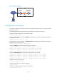
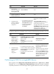
Figure 37 Network diagram
Configuration procedure
# Configure IP addresses and routes to make sure the device and the TFTP server can reach each other.
(Details not shown.)
# Complete TFTP settings on both the device and the TFTP server. (Details not shown.)
# Display information about the current software images.
<Sysname> display version
# Use TFTP to download the image file 11900.ipe from the TFTP server to the root directory of the flash on
the active MPU.
<Sysname> tftp 2.2.2.2 get 11900.ipe
# (Optional.) Back up the image file to 11900-backup.ipe. Skip this step if the flash does not have
sufficient space.
<Sysname> copy 11900.ipe 11900-backup.ipe
# Specify 11900.ipe as the main startup image file for both MPUs.
<Sysname> boot-loader file flash:/11900.ipe slot 4 main
<Sysname> boot-loader file flash:/11900.ipe slot 5 main
# Specify 11900-backup.ipe as the backup startup image file for both MPUs.
<Sysname> boot-loader file flash:/11900-backup.ipe slot 4 backup
<Sysname> boot-loader file flash:/11900-backup.ipe slot 5 backup
# Verify the startup image settings.
<Sysname> display boot-loader
# Reboot the device to complete the upgrade.
<Sysname> reboot
# Verify that the device is running the correct software.
<Sysname> display version
Software upgrade example (for IRF mode)
Network requirements
Use the file 119 0 0 . i p e to upgrade software images for the IRF fabric in Figure 38.
Each IRF member device has two MPUs: one in slot 4 and one in slot 5. The global active MPU is in slot
4 on the master device.
TFTP client
TFTP server
Device
2.2.2.2/24
Internet
1.1.1.1/24