HP FlexFabric 11900 Switch Series High Availability Command Reference Part number: 5998-5280 Software version: Release 2111 and later Document version: 6W100-20140110
Legal and notice information © Copyright 2014 Hewlett-Packard Development Company, L.P. No part of this documentation may be reproduced or transmitted in any form or by any means without prior written consent of Hewlett-Packard Development Company, L.P. The information contained herein is subject to change without notice.
Contents Ethernet OAM commands ··········································································································································· 1 display oam ······························································································································································ 1 display oam configuration······································································································································· 5 dis
display cfd service-instance ·································································································································· 49 display cfd status ··················································································································································· 51 DLDP commands ························································································································································· 52 display
bfd multi-hop detect-multiplier ······························································································································ 97 bfd multi-hop min-receive-interval ························································································································ 98 bfd multi-hop min-transmit-interval ······················································································································· 98 bfd session init-mode ··········
Ethernet OAM commands display oam Use display oam to display the information about an Ethernet OAM connection, including connection status, information contained in Ethernet OAM packet header, and Ethernet OAM packet statistics. Syntax display oam { local | remote } [ interface interface-type interface-number ] Views Any view Predefined user roles network-admin network-operator mdc-admin mdc-operator Parameters local: Displays the Ethernet OAM connection information of the local end.
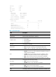
OAM mode : Active PDU : ANY Mux action : FWD Par action : FWD Flags Link fault : Not occurred Dying gasp : Not occurred Critical event : Not occurred Local evaluating : COMPLETE Remote evaluating : COMPLETE Packets statistics Packet type Sent Received ----------------------------------------------------------------OAMPDU 100 80 OAMInformation 64 60 OAMEventNotification 36 20 OAMUniqueEventNotification 36 10 OAMDuplicateEventNotification 0 10 Table 1 Command output Field De
Field Description Link fault Indicates whether an Ethernet OAM link error is present. Dying gasp Indicates whether a fatal error is present. Critical event Indicates whether a critical error is present. Indicates whether the local-to-remote configuration negotiation is complete: • COMPLETE—The negotiation is completed. • NOTCOMPLETE—The negotiation is uncompleted.
Critical event : Not occurred Local evaluating : COMPLETE Remote evaluating : COMPLETE Table 2 Command output Field Description Ten-GigabitEthernet1/0/1 Information on Ten-GigabitEthernet 1/0/1. Local Ethernet OAM mode: OAM mode • Active—The port operates in the active Ethernet OAM mode. • Passive—The port operates in the passive Ethernet OAM mode. MAC address MAC address of the remote end. MTU size MTU size, in bytes.
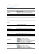
Related commands reset oam display oam configuration Use display oam configuration to display global Ethernet OAM configuration on the specified port, including the periods and thresholds for Ethernet OAM link error event detection. Syntax display oam configuration [ interface interface-type interface-number ] Views Any view Predefined user roles network-admin network-operator mdc-admin mdc-operator Parameters interface interface-type interface-number: Specifies a port by its type and number.
OAM timers Hello timer : 500 milliseconds Keepalive timer : 5000 milliseconds Link monitoring Errored symbol period Window : 100 x 1000000 symbols Threshold : 1 error symbols Errored frame Window : 10 x 100 milliseconds Threshold : 1 error frames Errored frame period Window : 1000 x 10000 frames Threshold : 1 error frames Errored frame seconds Window : 600 x 100 milliseconds Threshold : 1 error seconds Table 3 Command output Field Description Global Global information.
network-operator mdc-admin mdc-operator Parameters interface interface-type interface-number: Specifies a port by its type and number. Usage guidelines If you do not specify the interface keyword, this command displays the statistics for the critical Ethernet OAM link events that occurred on all the ports of the switch. Examples # Display the statistics on critical Ethernet OAM link events occurred on all the ports.
mdc-operator Parameters local: Displays the statistics on the local Ethernet OAM link error events. remote: Displays the statistics on the peer Ethernet OAM link error events. interface interface-type interface-number: Specifies a port by its type and number. Usage guidelines If you do not specify the interface keyword, this command displays the statistics on the Ethernet OAM link error events occurred on all the local/peer ports.
OAM remote errored frame event Event time stamp : 49582 x 100 milliseconds Errored frame window : 10 x 100 milliseconds Errored frame threshold : 1 error frames Errored frame : 1 error frames Error running total : 6 error frames Event running total : 6 events OAM remote errored frame period event Event time stamp : 16382 x 100 milliseconds Errored frame period window : 10000000 frames Errored frame period threshold : 1 error frames Errored frame period : 1 error frames Error running total
Field Description Information about local errored frame period events: OAM local/remote errored frame period event • Event time stamp—Time when an errored frame period event occurred. • Errored frame period window—Errored frame period detection interval. • Errored frame period threshold—Errored threshold that triggers an errored frame period event. • Errored frame period—Number of detected errored frames in the most recent errored frame period event.
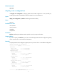
oam errored-frame threshold Use oam errored-frame threshold to set the errored frame event triggering threshold for a port. Use undo oam errored-frame threshold to restore the default. Syntax oam errored-frame threshold threshold-value undo oam errored-frame threshold Default The port uses the global setting.
Views Layer 2 Ethernet port view, Layer 3 Ethernet port view Predefined user roles network-admin mdc-admin Parameters window-value: Specifies the errored frame event detection window in the range of 10 to 600 and in steps of 10 (in 100 milliseconds). Usage guidelines The configuration in port view takes effect on the specified port. For a port, the configuration in port view takes precedence. Examples # Set the errored frame event detection window on Ten-GigabitEthernet 1/0/1 to 2000 milliseconds.
Usage guidelines The configuration in port view takes effect on the specified port. For a port, the configuration in port view takes precedence. Examples # Set the errored frame period event triggering threshold on Ten-GigabitEthernet 1/0/1 to 100.
• display oam link-event • oam global errored-frame-period window oam errored-frame-seconds threshold Use oam errored-frame-seconds threshold to set the errored frame seconds event triggering threshold on a port. Use undo oam errored-frame-seconds threshold to restore the default. Syntax oam errored-frame-seconds threshold threshold-value undo oam errored-frame-seconds threshold Default The port uses the global setting.
Use undo oam errored-frame-seconds window to restore the default. Syntax oam errored-frame-seconds window window-value undo oam errored-frame-seconds window Default The port uses the global setting. Views Layer 2 Ethernet port view, Layer 3 Ethernet port view Predefined user roles network-admin mdc-admin Parameters window-value: Specifies the errored frame seconds event detection window in the range of 100 to 9000 and in steps of 10 (in 100 milliseconds).
Default The port uses the global setting. Views Layer 2 Ethernet port view, Layer 3 Ethernet port view Predefined user roles network-admin mdc-admin Parameters threshold-value: Specifies the errored symbol event triggering threshold in the range of 0 to 4294967295. Usage guidelines The configuration in port view takes effect on the specified port. For a port, the configuration in port view takes precedence. Examples # Set the errored symbol event triggering threshold to 100.
Parameters window-value: Specifies the errored symbol event detection window in the range of 1 to 65535. The value of this argument must be a multiple of 1000000. Usage guidelines The configuration in port view takes effect on the specified port. For a port, the configuration in port view takes precedence. Examples # Set the errored symbol event detection window on Ten-GigabitEthernet 1/0/1 to 200000000.
Related commands • display oam configuration • display oam link-event • oam errored-frame threshold oam global errored-frame window Use oam global errored-frame window to set the global errored frame event detection window. Use undo oam global errored-frame window to restore the default. Syntax oam global errored-frame window window-value undo oam global errored-frame window Default The global errored frame event detection window is 1000 milliseconds.
Syntax oam global errored-frame-period threshold threshold-value undo oam global errored-frame-period threshold Default The errored frame period event triggering threshold is 1. Views System view Predefined user roles network-admin mdc-admin Parameters threshold-value: Specifies the errored frame period event triggering threshold in the range of 0 to 4294967295. Usage guidelines The configuration in system view takes effect on all ports, but has a lower precedence than the configuration in port view.
mdc-admin Parameters window-value: Specifies the errored frame period event detection window in the range of 1 to 65535. The value of this argument must be a multiple of 10000. Usage guidelines The configuration in system view takes effect on all ports, but has a lower precedence than the configuration in port view. Examples # Set the errored frame period event detection window to 20000000.
Examples # Set the errored frame seconds event triggering threshold to 100. system-view [Sysname] oam global errored-frame-seconds threshold 100 Related commands • display oam configuration • display oam link-event • oam errored-frame-seconds threshold • oam global errored-frame-seconds window oam global errored-frame-seconds window Use oam global errored-frame-seconds window to set the global errored frame seconds event detection window.
• display oam link-event • oam errored-frame-seconds period • oam global errored-frame-seconds threshold oam global errored-symbol-period threshold Use oam global errored-symbol-period threshold to set the global errored symbol event triggering threshold. Use undo oam global errored-symbol-period threshold to restore the default.
Syntax oam global errored-symbol-period window window-value undo oam global errored-symbol-period window Default The global errored symbol event detection window is 100000000. Views System view Predefined user roles network-admin mdc-admin Parameters window-value: Specifies the errored symbol event detection window in the range of 1 to 65535. The value of this argument must be a multiple of 1000000.
mdc-admin Parameters interval: Specifies the Ethernet OAM handshake packet transmission interval, in steps of 100 (in milliseconds). The value range for this argument is 500 to 5000. Usage guidelines After the timeout timer of an Ethernet OAM connection expires, the local OAM entity ages out its connection with the peer OAM entity, causing the OAM connection to disconnect.
OAM connections stable, HP recommends setting the connection timeout timer to be at least five times the handshake packet transmission interval. The configuration in system view takes effect on all ports, but has a lower precedence than the configuration in port view. Examples # Set the Ethernet OAM connection timeout timer to 6000 milliseconds.
Related commands oam enable oam remote-failure action Use oam remote-failure action to configure the action the port takes after it receives an Ethernet OAM event from the remote end. Use undo oam remote-failure action to restore the default.
Default The port uses the global setting. Views Layer 2 Ethernet port view, Layer 3 Ethernet port view Predefined user roles network-admin mdc-admin Parameters interval: Specifies the Ethernet OAM handshake packet transmission interval, in steps of 100 (in milliseconds). The value range for this argument is 500 to 5000.
mdc-admin Parameters interval: Specifies the Ethernet OAM connection timeout timer, in steps of 100 (in milliseconds). The value range for this argument is 1000 to 25000. Usage guidelines After the timeout timer of an Ethernet OAM connection expires, the local OAM entity ages out its connection with the peer OAM entity, causing the OAM connection to disconnect.
Related commands • display oam • display oam link-event 29
CFD commands cfd cc enable Use cfd cc enable to enable CCM sending on a specified MEP. Use undo cfd cc enable to disable CCM sending on a specified MEP. Syntax cfd cc service-instance instance-id mep mep-id enable undo cfd cc service-instance instance-id mep mep-id enable Default The CCM sending function is disabled.
undo cfd cc interval [ interval-value ] service-instance instance-id Default The value of this field is 4 for all CCMs sent. Views System view Predefined user roles network-admin mdc-admin Parameters interval interval-value: Specifies the value of the interval field in CCM messages, in the range of 1 to 7. The switch does not support a CCM interval field value in the range of 1 to 3. If you configure a CCM interval field value of 1, 2, or 3, the value of 4 takes effect.
Default CFD is disabled. Views System view Predefined user roles network-admin mdc-admin Examples # Enable CFD. system-view [Sysname] cfd enable cfd linktrace Use cfd linktrace to find the path between the source MEP and target MP, which is achieved through the transmission of LTMs between the two and detection of the responding LTRs.
Table 7 Command output Field Description Linktrace to MEP 2001 with the sequence number 1101-43361 Linktrace to target MEP 2001 with the sequence number 1101-43361. MAC Address Source MAC address in the LTR messages. TTL Hop count when the LTM passes the device. Last Mac MAC address of the last-hop device the LTM passes. Indicates whether the forwarding device found the destination MAC address in its MAC address table. When the standard version (IEEE 802.
will be sent out. (The destination of the LTMs is the target MEP, and the TTL field value is 255.) Based on the LTRs that echo back, the fault source can be located. Once you disable LT message automatic sending, the content stored in the buffer will be removed. Examples # Enable automatic LT messages sending, and set the size of the buffer used to store the auto-detection result to 100 (in terms of sending times).
Reply from 0010-fc00-6512: sequence number=1101-43408 Time=5ms Sent: 5 Received: 5 Lost: 0 # Enable LB to check the status of the link between MEP 1101 and MEP 2001 in service instance 1 (assume that the link status is abnormal).
index index-value: Specifies an MD index in the range of 1 to 4294967295. If this option is not specified, the system automatically assigns the smallest index number that is not in use. HP recommends using the index automatically assigned by the system. level level-value: Specifies an MD level in the range of 0 to 7. md-id: Specifies the MD name carried by packets sent by the MEP. If you do not provide the keyword, the MD name is represented by md-name.
Parameters mep mep-id: Specifies the ID of a MEP, in the range of 1 to 8191. service-instance instance-id: Specifies the service instance ID in the range of 1 to 32767. inbound: Creates an inward-facing MEP. outbound: Creates an outward-facing MEP. Usage guidelines In creating a MEP, the service instance you specified defines the MD and MA to which the MEP belongs. You cannot create a MEP if the MEP ID is not included in the MEP list of the relevant service instance.
Parameters meplist mep-list: Specifies a list of MEP IDs, indicating multiple MEPs, in the format of mep-list = { mep-id [ to mep-id ] }&<1-10>, in which mep-id represents the MEP ID and is in the range of 1 to 8191. &<1-10> indicates you can specify up to 10 MEP ID ranges. service-instance instance-id: Specifies the service instance ID in the range of 1 to 32767. Usage guidelines Before creating a MEP list, create the relevant MD, MA, and service instance.
Examples # Configure the MIP generation rule as default in service instance 5. system-view [Sysname] cfd mip-rule default service-instance 5 cfd service-instance Use cfd service-instance to create a service instance with the MD name. Use undo cfd service-instance to remove the service instance.
brackets ({ }, ( ),[ ], < >), hyphen (-), underscore (_), plus (+), equal sign (=), vertical bar (|), colon (:), semicolon (;), quotation mark ('), comma (,), period (.), and slash (/). vlan vlan-id: Specifies the VLAN that the MA serves, in the range of 1 to 4094. If this option is not provided, the MA does not serve any VLAN. Usage guidelines A service instance is indicated by an integer to represent an MA in an MD.
Usage guidelines This command displays only information about LTRs received by execution of the cfd linktrace command. Examples # Display the LTR information saved on all the MEPs in every service instance.
mdc-admin mdc-operator Parameters size size-value: Specifies the times of recent auto-detections, in the range of 1 to 100. If this option is not specified, all information in the buffer is displayed. Usage guidelines This command displays only information about LTRs received by execution of the cfd linktrace auto-detection command. Examples # Display the contents of the LTRs received as responses to the LTMs automatically sent.
display cfd md Use display cfd md to display the MD configuration information. Syntax display cfd md Views Any view Predefined user roles network-admin network-operator mdc-admin mdc-operator Examples # Display the MD configuration information. display cfd md CFD is enabled.
display cfd mep Use display cfd mep to display the attribute and operating information of a MEP. Syntax display cfd mep mep-id service-instance instance-id Views Any view Predefined user roles network-admin network-operator mdc-admin mdc-operator Parameters mep mep-id: Specifies a MEP by its ID in the range of 1 to 8191. service-instance instance-id: Specifies a service instance by its ID in the range of 1 to 32767.
One or more streams of error CCMs is received. The last received CCM: Maintenance domain: (Without ID) Maintenance association: matest1 MEP ID: 5 Sequence Number:0x50A MAC Address: 0011-2233-4402 Received Time: 2013/03/06 13:01:34 One or more streams of cross-connect CCMs is received.
Field SendCCM Description Number of CCMs that have been sent by the MEPs. If this field is not supported, a hyphen (-) is displayed. Loopback Information related to Loopback. NextSeqNumber Sequence number of the next LBM to be sent. SendLBR Number of LBRs that have been sent. If the MEP is inward-facing, the number of LBRs will not be counted. ReceiveInOrderLBR Number of LBR messages received in correct sequence. ReceiveOutOrderLBR Number of LBR messages received out of order.
Views Any view Predefined user roles network-admin network-operator mdc-admin mdc-operator Parameters service-instance instance-id: Specifies a service instance by its ID in the range of 1 to 32767. If this option is not specified, MEP lists in all service instances are displayed. Examples # Display the MEP list in service instance 5. display cfd meplist service-instance 5 Service instance: 5 MEP list: 1 to 20, 30, 50. display cfd mp Use display cfd mp to display the MP information.
MIP Level: 2 Service instance: 102 Maintenance domain: md_2 Maintenance domain index: 3 Maintenance association: ma_2 Maintenance association index: 3 MEP ID: 101 Level: 1 Service instance: 101 Direction: Inbound Maintenance domain: md_1 Maintenance domain index: 2 Maintenance association: ma_1 Maintenance association index: 2 MEP ID: 100 Level: 0 Service instance: 100 Direction: Outbound Maintenance domain: md_0 Maintenance domain index: 1 Maintenance association: ma_0 Maintenance association in
mdc-operator Parameters service-instance instance-id: Specifies the service instance ID in the range of 1 to 32767. mep mep-id: Specifies the ID of a remote MEP, in the range of 1 to 8191. Examples # Display information about remote MEP 10 in service instance 4.
network-operator mdc-admin mdc-operator Parameters instance-id: Specifies a service instance ID in the range of 1 to 32767. If this argument is not specified, the configuration information of all service instances is displayed. Examples # Display the configuration information of all service instances.
display cfd status Use display cfd status to display the CFD status. Syntax display cfd status Views Any view Predefined user roles network-admin network-operator mdc-admin mdc-operator Examples # Display the CFD status. display cfd status CFD is enabled.
DLDP commands display dldp Use display dldp to display DLDP configuration. Syntax display dldp [ interface interface-type interface-number ] Views Any view Predefined user roles network-admin network-operator mdc-admin mdc-operator Parameters interface interface-type interface-number: Specifies an interface by its type and number. Usage guidelines If no port is specified, this command displays global and port-specific DLDP configuration.
Number of the port’s neighbors: 0 (Maximum number ever detected: 1) # Display the DLDP configuration of Ten-GigabitEthernet 1/0/1. display dldp interface ten-gigabitethernet 1/0/1 Interface Ten-GigabitEthernet1/0/1 DLDP port state: Bidirectional Number of the port’s neighbors: 1 Neighbor MAC address: 0023-8956-3600 Neighbor port index: 79 Neighbor state: Confirmed Neighbor aged time: 13s Table 16 Command output Field Description DLDP global status Global DLDP state (Enabled or Disabled).
Syntax display dldp statistics [ interface interface-type interface-number ] Views Any view Predefined user roles network-admin network-operator mdc-admin mdc-operator Parameters interface interface-type interface-number: Specifies a port by its type and number. Usage guidelines If no port is specified, this command displays the statistics on the DLDP packets passing through all the DLDP-enabled ports. Examples # Display the statistics on the DLDP packets passing through all the DLDP-enabled ports.
Field Description Valid packets received Number of the valid packets received. Related commands reset dldp statistics dldp authentication-mode Use dldp authentication-mode to configure DLDP authentication. Use undo dldp authentication-mode to restore the default. Syntax dldp authentication-mode { md5 | none | simple } undo dldp authentication-mode Default DLDP authentication is not performed.
Related commands • display dldp • dldp authentication-password dldp authentication-password Use dldp authentication-password to configure the password for DLDP authentication. Use undo dldp authentication-password to restore the default. Syntax dldp authentication-password { cipher cipher | simple simple } undo dldp authentication-password Default No DLDP authentication password is configured.
Related commands • display dldp • dldp authentication-mode dldp delaydown-timer Use dldp delaydown-timer to set the DelayDown timer. Use undo dldp delaydown-timer to restore the default. Syntax dldp delaydown-timer time undo dldp delaydown-timer Default The setting of the DelayDown timer is 1 second. Views System view Predefined user roles network-admin mdc-admin Parameters time: Specifies the DelayDown timer in the range of 1 to 5 seconds.
Views Layer 2 Ethernet interface view, Layer 3 Ethernet interface view Predefined user roles network-admin mdc-admin Usage guidelines DLDP can take effect only after you enable it globally and on a port. Examples # Enable DLDP globally, and then enable DLDP on Ten-GigabitEthernet 1/0/1.
• dldp enable dldp interval Use dldp interval to set the interval for sending Advertisement packets. Use undo dldp interval to restore the default. Syntax dldp interval time undo dldp interval Default The interval for sending Advertisement packets is 5 seconds. Views System view Predefined user roles network-admin mdc-admin Parameters time: Specifies Advertisement packets sending interval in the range of 1 to 100 seconds. Usage guidelines This command applies to all DLDP-enabled ports.
Views System view Predefined user roles network-admin mdc-admin Parameters auto: Configures the port shutdown mode as auto mode. In this mode, when DLDP detects a unidirectional link, it shuts down the Unidirectional port. manual: Configures the port shutdown mode as manual mode. In this mode, when DLDP detects a unidirectional link, DLDP does not shut down the involved port but you need to manually shut it down. When the link state is restored to Bidirectional, you must manually bring up the port.
VRRP commands The term "interface" in this chapter collectively refers to VLAN interfaces and Layer 3 Ethernet interfaces. You can set an Ethernet port as a Layer 3 interface by using the port link-mode route command (see Layer 2—LAN Switching Configuration Guide). IPv4 VRRP commands display vrrp Use display vrrp to display the states of IPv4 VRRP groups.
Interface VRID State Running Adver Auth Virtual Pri Type IP Timer --------------------------------------------------------------------Vlan2 1 Master 150 100 Simple 1.1.1.1 Table 18 Command output (in standard mode) Field Description Running Mode VRRP operating mode (standard mode). Total number of virtual routers Total number of VRRP groups. Interface Interface where the VRRP group is configured. VRID Virtual router ID (VRRP group number).
Admin Status : Up State : Backup Config Pri : 80 Running Pri : 80 Preempt Mode : Yes Delay Time : 0 Become Master : 2370ms left Auth Type : None Virtual IP : 1.1.1.11 Master IP : 1.1.1.12 Table 19 Command output (in standard mode) Field Description Running Mode VRRP operating mode (standard mode). Total number of virtual routers Total number of VRRP groups. Interface Interface where the VRRP group is configured. VRID Virtual router ID (VRRP group number).
Field Description Track Object Track entry which is associated with the VRRP group. Track entry state: State • Negative. • Positive. • NotReady. Pri Reduced Value by which the priority decreases when the status of the associated track entry becomes negative. Switchover Switchover mode. When the status of the associated track entry becomes negative, the backup immediately becomes the master. display vrrp statistics Use display vrrp statistics to display statistics for IPv4 VRRP groups.
IP TTL Errors : 0 Advertisement Interval Errors : 0 Invalid Auth Type : 0 Auth Failures : 0 Packet Length Errors : 0 Auth Type Mismatch : 0 Become Master : 1 Address List Errors : 0 Adver Rcvd : 0 Priority Zero Pkts Rcvd : 0 Adver Sent : 807 Priority Zero Pkts Sent : 0 Global statistics CheckSum Errors : 0 Version Errors : 0 VRID Errors : 0 Table 20 Command output (in standard mode) Field Description Interface Interface where the VRRP group is configured.
reset vrrp statistics Use reset vrrp statistics to clear statistics for IPv4 VRRP groups. Syntax reset vrrp statistics [ interface interface-type interface-number [ vrid virtual-router-id ] ] Views User view Predefined user roles network-admin mdc-admin Parameters interface interface-type interface-number: Specifies an interface by its type and number. vrid virtual-router-id: Specifies an IPv4 VRRP group by its virtual router ID in the range of 1 to 255.
mdc-admin Parameters auth-failure: Generates notifications as defined in RFC 2787 when the device in a VRRP group receives a VRRP advertisement with the authentication type or key not matching the local configuration. new-master: Generates notifications as defined in RFC 2787 when the state of a device in a VRRP group changes from Initialize or Backup to Master. Usage guidelines When the notification function is enabled, the device can send notifications to the destination host.
[Sysname] interface vlan-interface 2 [Sysname-Vlan-interface2] undo vrrp check-ttl enable vrrp dscp Use vrrp dscp to configure a DSCP value for VRRP packets. Use undo vrrp dscp to restore the default. Syntax vrrp dscp dscp-value undo vrrp dscp Views System view Predefined user roles network-admin mdc-admin Parameters dscp-value: Specifies a DSCP value for VRRP packets, in the range of 0 to 63. The default is 48. Usage guidelines The DSCP value identifies the packet priority during transmission.
Parameters version-number: Specifies a VRRP version. The version number is 2 or 3, where 2 indicates VRRPv2 (described in RFC 3768), and 3 indicates VRRPv3 (described in RFC 5798). Usage guidelines The version of VRRP on all routers in an IPv4 VRRP group must be the same. Examples # Specify VRRPv2 to run on VLAN-interface 10.
The sender fills an authentication key into the VRRP packet, and the receiver compares the received authentication key with its local authentication key. If the two authentication keys are the same, the received VRRP packet is legitimate. Otherwise, the received packet is illegitimate. • md5—MD5 authentication. The sender computes a digest for the packet to be sent by using the authentication key and MD5 algorithm, and it saves the result in the authentication header.
Predefined user roles network-admin mdc-admin Parameters virtual-router-id: Specifies an IPv4 VRRP group by its virtual router ID in the range of 1 to 255. delay delay-value: Specifies a preemption delay time in the range of 0 to 255 in seconds. The default setting is 0 seconds. Usage guidelines In non-preemptive mode, when a device in the IPv4 VRRP group becomes the master, it acts as the master as long as it operates correctly, even if a backup is assigned a higher priority later.
Parameters virtual-router-id: Specifies an IPv4 VRRP group by its virtual router ID in the range of 1 to 255. priority-value: Specifies a priority value in the range of 1 to 254. A higher number indicates a higher priority. Usage guidelines VRRP determines the role (master or backup) of each device in a VRRP group by priority. A device with a higher priority is more likely to become the master. VRRP priority is in the range of 0 to 255, and a greater number represents a higher priority.
Examples # Disable IPv4 VRRP group 1. system-view [Sysname] interface vlan-interface 2 [Sysname-Vlan-interface2] vrrp vrid 1 shutdown vrrp vrid source-interface Use vrrp vrid source-interface to specify the source interface for an IPv4 VRRP group. This interface, instead of the interface where the VRRP group resides, sends and receives VRRP packets. Use undo vrrp source-interface to cancel the specified source interface.
Syntax vrrp vrid virtual-router-id timer advertise adver-interval undo vrrp vrid virtual-router-id timer advertise Default The master in an IPv4 VRRP group sends VRRP advertisements at an interval of 100 centiseconds. Views Interface view Predefined user roles network-admin mdc-admin Parameters virtual-router-id: Specifies an IPv4 VRRP group by its virtual router ID in the range of 1 to 255.
vrrp vrid track Use vrrp vrid track to associate a VRRP group with a track entry and control master switchover in the VRRP group in response to changes (such as uplink state changes) detected by the track entry. Use undo vrrp vrid track to remove the association between a VRRP group and a track entry. If no track entry is specified, the association between the VRRP group and any track entry is removed.
Examples # Associate VRRP group 1 on VLAN-interface 2 with track entry 1 and decrease the priority of the router in the VRRP group by 50 when the state of track entry 1 changes to negative. system-view [Sysname] interface vlan-interface 2 [Sysname-Vlan-interface2] vrrp vrid 1 track 1 reduced 50 Related commands display vrrp vrrp vrid Use vrrp vrid to create an IPv4 VRRP group and assign a virtual IP address to the IPv4 VRRP group or assign a virtual IP address to an existing IPv4 VRRP group.
system-view [Sysname] interface vlan-interface 2 [Sysname-Vlan-interface2] vrrp vrid 1 virtual-ip 10.10.10.10 [Sysname-Vlan-interface2] vrrp vrid 1 virtual-ip 10.10.10.11 Related commands display vrrp IPv6 VRRP commands display vrrp ipv6 Use display vrrp ipv6 to display the states of IPv6 VRRP groups.
--------------------------------------------------------------------Vlan2 1 Master 150 100 None FE80::10 Table 21 Command output (in standard mode) Field Description Running Mode VRRP operating mode (standard mode). Total number of virtual routers Total number of VRRP groups. Interface Interface where the VRRP group is configured. VRID Virtual router ID (VRRP group number). Status of the router in the VRRP group: • • • • State Master. Backup. Initialize. Inactive.
Auth Type : None Virtual IP : FE80::11 Virtual MAC : 0000-5e00-020b Master IP : FE80::2 1::11 Table 22 Command output (in standard mode) Field Description Running Mode VRRP operating mode (standard mode). Total number of virtual routers Total number of VRRP groups. Interface Interface where the VRRP group is configured. VRID Virtual router ID (VRRP group number). Adver Timer VRRP advertisement sending interval in centiseconds. Admin Status Administrative status: up or down.
Field Description Pri Reduced Value by which the priority decreases when the status of the associated track entry becomes negative. Switchover Switchover mode. When the status of the associated track entry becomes negative, the backup immediately becomes the master. display vrrp ipv6 statistics Use display vrrp ipv6 statistics to display statistics for IPv6 VRRP groups.
Global statistics CheckSum Errors : 0 Version Errors : 0 VRID Errors : 0 Table 23 Command output (in standard mode) Field Description Interface Interface where the VRRP group is configured. VRID VRRP group number. CheckSum Errors Number of packets with checksum errors. Version Errors Number of packets with version errors. Invalid Pkts Rcvd Number of received packets of invalid packet types. Unexpected Pkts Rcvd Number of received unexpected packets.
Views User view Predefined user roles network-admin mdc-admin Parameters interface interface-type interface-number: Specifies an interface by its type and number. vrid virtual-router-id: Specifies an IPv6 VRRP group by its virtual router ID in the range of 1 to 255. Usage guidelines • If no interface or VRRP group is specified, this command clears statistics for all IPv6 VRRP groups.
Examples # Configure the DSCP value for IPv6 VRRP packets as 30. system-view [Sysname] vrrp ipv6 dscp 30 vrrp ipv6 vrid preempt-mode Use vrrp ipv6 vrid preempt-mode to enable the preemptive mode for the router in an IPv6 VRRP group and configure the preemption delay time. Use undo vrrp ipv6 vrid preempt-mode to disable the preemptive mode for the router in an IPv6 VRRP group. Use undo vrrp ipv6 vrid preempt-mode delay to restore the default preemption delay.
[Sysname-Vlan-interface2] vrrp ipv6 vrid 10 preempt-mode delay 5 Related commands display vrrp ipv6 vrrp ipv6 vrid priority Use vrrp ipv6 vrid priority to configure the priority of the router in an IPv6 VRRP group. Use undo vrrp ipv6 vrid priority to restore the default. Syntax vrrp ipv6 vrid virtual-router-id priority priority-value undo vrrp ipv6 vrid virtual-router-id priority Default The priority of a router in an IPv6 VRRP group is 100.
Use undo vrrp ipv6 vrid shutdown to restore the default. Syntax vrrp ipv6 vrid virtual-router-id shutdown undo vrrp ipv6 vrid virtual-router-id shutdown Default An IPv6 VRRP group is enabled. Views Interface view Predefined user roles network-admin mdc-admin Parameters virtual-router-id: Specifies an IPv6 VRRP group by its virtual router ID in the range of 1 to 255. Usage guidelines You can use this command to temporarily disable an IPv6 VRRP group.
Parameters virtual-router-id: Specifies an IPv6 VRRP group by its virtual router ID in the range of 1 to 255. adver-interval: Specifies an interval for the master in the specified IPv6 VRRP group to send VRRP advertisements. The value range for this argument is 10 to 4095 centiseconds. For VRRPv2, the value of the adver-interval argument can only be a multiple of 100.
Predefined user roles network-admin mdc-admin Parameters virtual-router-id: Specifies an IPv6 VRRP group number in the range of 1 to 255. track-entry-number: Specifies a track entry. The track-entry-number argument is in the range of 1 to 1024. reduced priority-reduced: Reduces the priority of the router in the VRRP group by a specific value when the state of the specified track entry changes to negative. The priority-reduced argument is in the range of 1 to 255.
Syntax vrrp ipv6 vrid virtual-router-id virtual-ip virtual-address [ link-local ] undo vrrp ipv6 vrid virtual-router-id [ virtual-ip [ virtual-address [ link-local ] ] ] Default No IPv6 VRRP group is created. Views Interface view Predefined user roles network-admin mdc-admin Parameters virtual-router-id: Specifies an IPv6 VRRP group by its virtual router ID in the range of 1 to 255. virtual-ip virtual-address: Specifies a virtual IPv6 address.
BFD commands The term "interface" in this chapter collectively refers to VLAN interfaces and Layer 3 Ethernet interfaces. You can set an Ethernet port as a Layer 3 interface by using the port link-mode route command (see Layer 2—LAN Switching Configuration Guide). bfd authentication-mode Use bfd authentication-mode to configure the BFD authentication mode for single-hop BFD control packets. Use undo bfd authentication-mode to restore the default.
[Sysname-Vlan-interface11] bfd authentication-mode simple 1 plain 123456 bfd demand enable Use bfd demand enable to enable the Demand BFD session mode. Use undo bfd demand enable to restore the default. Syntax bfd demand enable undo bfd demand enable Default The BFD session is in Asynchronous mode. Views Interface view Predefined user roles network-admin mdc-admin Usage guidelines In demand mode, no BFD control packets are exchanged after the session is established.
Views Interface view Predefined user roles network-admin mdc-admin Parameters value: Specifies a single-hop detection time multiplier in the range of 3 to 50. Usage guidelines The detection time multiplier determines the maximum number of concurrent BFD packets (including control packets and echo packets) that can be discarded.
Usage guidelines If you enable the echo packet mode for a BFD session in which control packets are sent and the session comes up, BFD does the following: • Periodically sends echo packets to detect link connectivity. • Decreases the control packet receiving rate at the same time. Examples # Enable the echo packet mode on VLAN-interface 11.
Syntax bfd echo-source-ipv6 ipv6-address undo bfd echo-source-ipv6 Default No source IPv6 address is configured for BFD echo packets. Views System view Predefined user roles network-admin mdc-admin Parameters ipv6-address: Specifies the source IPv6 address for BFD echo packets. Usage guidelines The source IPv6 address of echo packets can only be a global unicast address. The source IPv6 address cannot be on the same network segment as any local interface's IP address.
Usage guidelines This command sets the BFD echo packet receiving interval, which is the actual BFD echo packet sending interval. Examples # Configure the minimum interval for receiving BFD echo packets on VLAN-interface 11 as 500 milliseconds. system-view [Sysname] interface vlan-interface 11 [Sysname-Vlan-interface11] bfd min-echo-receive-interval 500 bfd min-receive-interval Use bfd min-receive-interval to configure the minimum interval for receiving single-hop BFD control packets.
bfd min-transmit-interval Use bfd min-transmit-interval to configure the minimum interval for transmitting single-hop BFD control packets. Use undo bfd min-transmit-interval to restore the default. Syntax bfd min-transmit-interval value undo bfd min-transmit-interval Default The minimum interval for transmitting single-hop BFD control packets is 400 milliseconds.
Views System view Predefined user roles network-admin mdc-admin Parameters simple: Specifies the simple authentication mode. key-id: Sets the authentication key ID in the range of 1 to 255. cipher: Sets a ciphertext password. cipher-string: Sets the ciphertext password, which is a case-sensitive string of 33 to 53 characters. plain: Sets a plaintext password. plain-string: Sets the plaintext password, which is a case-sensitive string of 1 to 16 characters.
Parameters port-number: Specifies the destination port number of multi-hop BFD control packets, 3784 or 4784. Examples # Configure the destination port number for multi-hop BFD control packets as 3784. system-view [Sysname] bfd multi-hop destination-port 3784 bfd multi-hop detect-multiplier Use bfd multi-hop detect-multiplier to configure the multi-hop detection time multiplier. Use undo bfd multi-hop detect-multiplier to restore the default.
bfd multi-hop min-receive-interval Use bfd multi-hop min-receive-interval to configure the minimum interval for receiving multi-hop BFD control packets. Use undo bfd multi-hop min-receive-interval to restore the default. Syntax bfd multi-hop min-receive-interval value undo bfd multi-hop min-receive-interval Default The minimum interval for receiving multi-hop BFD control packets is 400 milliseconds.
Predefined user roles network-admin mdc-admin Parameters value: Specifies the minimum interval for transmitting multi-hop BFD control packets, in milliseconds. The value range for this argument is 100 to 1000. Usage guidelines Use this command to make sure that the BFD packet sending rate does not exceed the device capability.
system-view [Sysname] bfd session init-mode passive display bfd session Use display bfd session to display BFD session information. Syntax display bfd session [ discriminator value | verbose ] Views Any view Predefined user roles network-admin network-operator mdc-admin mdc-operator Parameters discriminator value: Specifies a local ID in the range of 1 to 4294967295. If this option is not specified, the command displays brief information about all BFD sessions.
Total Session Num: 1 Up Session Num: 1 Init Mode: Active IPv4 Session Working Under Ctrl Mode: Local Discr: 513 Remote Discr: 513 Source IP: 1.1.1.1 Destination IP: 1.1.1.
Field Description Source IP/SourceAddr Source IP address of the session. Destination IP/DestAddr Destination IP address of the session. Session State/State Session state: up or down. Interface Name of the interface of the session. Min Tx Inter Minimum transmit interval. Min Rx Inter Minimum receive interval. Act Tx Inter Actual transmit interval. Detect Inter Actual session detection timer. Rx Count Number of packets received. Tx Count Number of packets sent.
Track commands display track Use display track to display track entry information. Syntax display track { track-entry-number | all } Views Any view Predefined user roles network-admin network-operator mdc-admin mdc-operator Parameters track-entry-number: Displays information about the specified track entry. The value range for the track-entry-number argument is 1 to 1024. all: Displays information about all track entries. Examples # Display information about all track entries.
Duration: 0 days 0 hours 0 minutes 32 seconds Notification delay: Positive 20, Negative 30 (in seconds) Tracked object: Interface: Vlan-interface3 Protocol: IPv4 Track ID: 4 State: Negative Duration: 0 days 0 hours 0 minutes 32 seconds Notification delay: Positive 20, Negative 30 (in seconds) Tracked object: CFD service instance: 1, MEP ID: 2 Table 27 Command output Field Description Track ID ID of a track entry.
• track interface • track interface protocol • track nqa track bfd Use track bfd to create a track entry and associate it with a BFD session. Use undo track to remove the track entry. Syntax track track-entry-number bfd echo interface interface-type interface-number remote ip remote-ip local ip local-ip [ delay { negative negative-time | positive positive-time } * ] undo track track-entry-number Default No track entry exists.
Examples # Create track entry 1, which uses BFD to monitor the link between local IP address 1.1.1.2 and remote IP address 1.1.1.1 by sending BFD echo packets out from the VLAN-interface 2. system-view [Sysname] track 1 bfd echo interface vlan-interface 2 remote ip 1.1.1.1 local ip 1.1.1.2 Related commands display track track cfd Use track cfd to create a track entry and associate it with CFD. Use undo track to remove the track entry.
Examples # Create track entry 1, and specify the CFD service instance ID as 2 and MEP ID as 3. system-view [Sysname] track 1 cfd cc service-instance 2 mep 3 Related commands • display track • cfd mep • cfd service-instance track nqa Use track nqa to create a track entry and associate it with the specified reaction entry of the NQA test group. Use undo track to remove the track entry.
positive positive-time: Specifies the amount of time the Track module waits before notifying the application modules that the state of the track entry has changed to Positive. The positive-time argument represents the delay time in the range of 1 to 300 seconds. Usage guidelines After a track entry is created, you can only use the track nqa delay command to modify its notification delay settings. To modify other settings, you must delete the entry and create a new one.
positive positive-time: Specifies the amount of time the Track module waits before notifying the application modules that the state of the track entry has changed to Positive. The positive-time argument represents the delay time in the range of 1 to 300 seconds. Usage guidelines When you create a track entry that is associated with the link state of a specific interface, the state of the track entry is Positive if the link state of the interface is up.
ipv6: Monitors the IPv6 protocol state. When the IPv6 protocol state of an interface is up, the state of the track object is Positive. When the IPv6 protocol state of an interface is down, the state of the track object is Negative. To display the IPv6 protocol state of an interface, use the display ipv6 interface brief command. delay: Specifies the amount of time the Track module waits before notifying the application modules that the track entry state has changed.
Support and other resources Contacting HP For worldwide technical support information, see the HP support website: http://www.hp.
Conventions This section describes the conventions used in this documentation set. Command conventions Convention Description Boldface Bold text represents commands and keywords that you enter literally as shown. Italic Italic text represents arguments that you replace with actual values. [] Square brackets enclose syntax choices (keywords or arguments) that are optional. { x | y | ... } Braces enclose a set of required syntax choices separated by vertical bars, from which you select one.
Network topology icons Represents a generic network device, such as a router, switch, or firewall. Represents a routing-capable device, such as a router or Layer 3 switch. Represents a generic switch, such as a Layer 2 or Layer 3 switch, or a router that supports Layer 2 forwarding and other Layer 2 features. Represents an access controller, a unified wired-WLAN module, or the switching engine on a unified wired-WLAN switch. Represents an access point.
Index BCDORSTVW display cfd service-instance,49 B display cfd status,51 bfd authentication-mode,89 display dldp,52 bfd demand enable,90 display dldp statistics,53 bfd detect-multiplier,90 display oam,1 bfd echo enable,91 display oam configuration,5 bfd echo-source-ip,92 display oam critical-event,6 bfd echo-source-ipv6,92 display oam link-event,7 bfd min-echo-receive-interval,93 display track,103 bfd min-receive-interval,94 display vrrp,61 bfd min-transmit-interval,95 display vrrp ipv6,7
oam global errored-symbol-period window,22 V oam global timer hello,23 vrrp check-ttl enable,67 oam global timer keepalive,24 vrrp dscp,68 oam mode,25 vrrp ipv6 dscp,82 oam remote-failure action,26 vrrp ipv6 vrid,87 oam timer hello,26 vrrp ipv6 vrid preempt-mode,83 oam timer keepalive,27 vrrp ipv6 vrid priority,84 R vrrp ipv6 vrid shutdown,84 reset bfd session statistics,102 vrrp ipv6 vrid timer advertise,85 vrrp ipv6 vrid track,86 reset dldp statistics,60 vrrp version,68 reset oam,28 v