
R211x-HP Flexfabric 11900 High Availability Configuration Guide
81
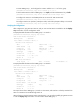
# Display detailed information about VRRP group 1 on Switch A when a fault is on the link between
Switch A and Switch C.
IPv4 Virtual Router Information:
Running Mode : Standard
Total number of virtual routers : 1
Interface Vlan-interface2
VRID : 1 Adver Timer : 500
Admin Status : Up State : Backup
Config Pri : 110 Running Pri : 80
Preempt Mode : Yes Delay Time : 5
Become Master : 2200ms left
Auth Type : Simple Key : ******
Virtual IP : 10.1.1.10
Master IP : 10.1.1.2
VRRP Track Information:
Track Object : 1 State : Negative Pri Reduced : 30
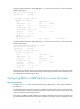
# Display detailed information about VRRP group 1 on Switch B when a fault is on the link between
Switch A and Switch C.
[SwitchB-Vlan-interface2] display vrrp verbose
IPv4 Virtual Router Information:
Running Mode : Standard
Total number of virtual routers : 1
Interface Vlan-interface2
VRID : 1 Adver Timer : 500
Admin Status : Up State : Master
Config Pri : 100 Running Pri : 100
Preempt Mode : Yes Delay Time : 5
Auth Type : Simple Key : ******
Virtual IP : 10.1.1.10
Virtual MAC : 0000-5e00-0101
Master IP : 10.1.1.2
The output shows that when a fault is on the link between Switch A and Switch C, the priority of Switch
A decreases to 80. Switch A becomes the backup, and Switch B becomes the master. Packets from Host
A to Host B are forwarded through Switch B.
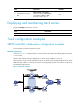
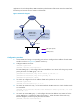
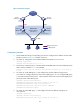
Configuring BFD for a VRRP backup to monitor the master
Network requirements
As shown in Figure 22, Switch A and Switch B belong to VRRP group 1, whose virtual IP address is
192.168.0.10.
The default gateway of the hosts in the LAN is 192.168.0.10. When Switch A works correctly, the hosts
in the LAN access the external network through Switch A. When Switch A fails, the hosts in the LAN
access the external network through Switch B.
If the master in a VRRP group fails and BFD is not configured, the backup cannot become the master until
the configured timeout timer expires. The timeout is usually 3 to 4 seconds, which is a long delay for most