
R211x-HP Flexfabric 11900 High Availability Configuration Guide

88
Static routing-Track-NQA collaboration configuration example
Network requirements
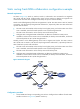
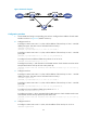
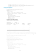
As shown in Figure 24, Switch A, Switch B, Switch C, and Switch D are connected to two segments
20.1.1.0/24 and 30.1.1.0/24. Configure static routes on these switches so that the two segments can
communicate with each other. Configure route backup to improve network reliability.
Switch A is the default gateway of the hosts in segment 20.1.1.0/24. Two static routes to 30.1.1.0/24 exist
on Switch A, with the next hop being Switch B and Switch C, respectively. These two static routes back
up each other as follows:
• The static route with Switch B as the next hop has a higher priority, and is the master route. If this
route is available, Switch A forwards packets to 30.1.1.0/24 through Switch B.
• The static route with Switch C as the next hop acts as the backup route.
• Configure static routing-Track-NQA collaboration to determine whether the master route is
available in real time. If the master route is unavailable, the backup route takes effect, and Switch
A forwards packets to 30.1.1.0/24 through Switch C.
Similarly, Switch D is the default gateway of the hosts in segment 30.1.1.0/24. Two static routes to
20.1.1.0/24 exist on Switch D, with the next hop being Switch B and Switch C, respectively. These two
static routes back up each other as follows:
• The static route with Switch B as the next hop has a higher priority, and is the master route. If this
route is available, Switch D forwards packets to 20.1.1.0/24 through Switch B.
• The static route with Switch C as the next hop acts as the backup route.
• Configure static routing-Track-NQA collaboration to determine whether the master route is
available in real time. If the master route is unavailable, the backup route takes effect, and Switch
D forwards packets to 20.1.1.0/24 through Switch C.
Figure 24 Network diagram
Configuration procedure
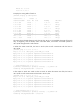
1. Create VLANs and assign corresponding ports to them. Configure the IP address of each VLAN
interface as shown in Figure 24. (Details not shown.)