
R211x-HP Flexfabric 11900 High Availability Configuration Guide

93
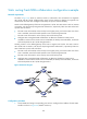
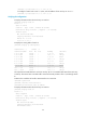
Figure 25 Network diagram
Configuration procedure
1. Create VLANs and assign corresponding ports to them. Configure the IP address of each VLAN
interface as shown in Figure 25. (Details not shown.)
2. Conf
igure Switch A:
# Configure a static route to 30.1.1.0/24, with the address of the next hop as 10.2.1.2 and the
default priority 60. This static route is associated with track entry 1.
<SwitchA> system-view
[SwitchA] ip route-static 30.1.1.0 24 10.2.1.2 track 1
# Configure a static route to 30.1.1.0/24, with the address of the next hop as 10.3.1.3 and the
priority 80.
[SwitchA] ip route-static 30.1.1.0 24 10.3.1.3 preference 80
# Configure the source address of BFD echo packets as 10.10.10.10.
[SwitchA] bfd echo-source-ip 10.10.10.10
# Configure track entry 1, and associate it with the BFD session. Check whether Switch A can be
interoperated with the next hop of static route (Switch B).
[SwitchA] track 1 bfd echo interface vlan-interface 2 remote ip 10.2.1.2 local ip
10.2.1.1
3. Configure Switch B:
# Configure a static route to 20.1.1.0/24, with the address of the next hop as 10.2.1.1 and the
default priority 60. This static route is associated with track entry 1.
<SwitchB> system-view
[SwitchB] ip route-static 20.1.1.0 24 10.2.1.1 track 1
# Configure a static route to 20.1.1.0/24, with the address of the next hop as 10.4.1.3 and the
priority 80.
[SwitchB] ip route-static 20.1.1.0 24 10.4.1.3 preference 80
# Configure the source address of BFD echo packets as 1.1.1.1.
[SwitchB] bfd echo-source-ip 1.1.1.1
# Configure track entry 1 that is associated with the BFD session to check whether Switch B can
communicate with the next hop (Switch A) of the static route.
[SwitchB] track 1 bfd echo interface vlan-interface 2 remote ip 10.2.1.1 local ip
10.2.1.2
4. Configure Switch C:
# Configure a static route to 30.1.1.0/24, with the address of the next hop as 10.4.1.2.
<SwitchC> system-view