HP FlexFabric 11900 Switch Series IP Multicast Configuration Guide Part number: 5998-5260 Software version: Release 2111 and later Document version: 6W100-20140110
Legal and notice information © Copyright 2014 Hewlett-Packard Development Company, L.P. No part of this documentation may be reproduced or transmitted in any form or by any means without prior written consent of Hewlett-Packard Development Company, L.P. The information contained herein is subject to change without notice.
Contents Multicast overview ······················································································································································· 1 Introduction to multicast ···················································································································································· 1 Information transmission techniques ·····················································································································
Enabling IP multicast routing ········································································································································· 39 Configuring multicast routing and forwarding ············································································································ 39 Configuring static multicast routes ······················································································································· 40 Configuring the RPF route
Configuration prerequisites ·································································································································· 75 Enabling PIM-SM ··················································································································································· 75 Configuring an RP ················································································································································· 75 Configuring a BS
MLD snooping configuration examples ····················································································································· 121 IPv6 group policy configuration example ········································································································· 121 Static port configuration example ····················································································································· 123 Troubleshooting MLD snooping ···················
Configuring IPv6 PIM-DM graft retry timer ······································································································· 159 Configuring IPv6 PIM-SM ············································································································································ 159 IPv6 PIM-SM configuration task list···················································································································· 159 Configuration prerequisites ·········
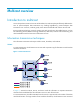
Multicast overview Introduction to multicast As a technique that coexists with unicast and broadcast, the multicast technique effectively addresses the issue of point-to-multipoint data transmission. By enabling high-efficiency point-to-multipoint data transmission over a network, multicast greatly saves network bandwidth and reduces network load.
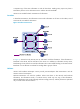
a separate copy of the same information to each of these hosts. Sending many copies can place a tremendous pressure on the information source and the network bandwidth. Unicast is not suitable for batch transmission of information. Broadcast In broadcast transmission, the information source sends information to all hosts on the subnet, even if some hosts do not need the information. Figure 2 Broadcast transmission In Figure 2, assume that only Host B, Host D, and Host E need the information.
Figure 3 Multicast transmission The multicast source sends only one copy of the information to a multicast group. Host B, Host D, and Host E, which are information receivers, must join the multicast group. The routers on the network duplicate and forward the information based on the distribution of the group members. Finally, the information is correctly delivered to Host B, Host D, and Host E.
For a better understanding of the multicast concept, you can compare multicast transmission to the transmission of TV programs. Table 1 Comparing TV program transmission and multicast transmission TV program transmission Multicast transmission A TV station transmits a TV program through a channel. A multicast source sends multicast data to a multicast group. A user tunes the TV set to the channel. A receiver joins the multicast group.
Multicast models Based on how the receivers treat the multicast sources, the multicast models include any-source multicast (ASM), source-filtered multicast (SFM), and source-specific multicast (SSM). ASM model In the ASM model, any sender can send information to a multicast group as a multicast source, and receivers can join a multicast group identified by a group address and get multicast information addressed to that multicast group.
Multicast addresses IP multicast addresses • IPv4 multicast addresses: IANA assigns the Class D address block (224.0.0.0 to 239.255.255.255) to IPv4 multicast. Table 2 Class D IP address blocks and description Address block Description 224.0.0.0 to 224.0.0.255 Reserved permanent group addresses. The IP address 224.0.0.0 is reserved. Other IP addresses can be used by routing protocols and for topology searching, protocol maintenance, and so on. Table 3 lists common permanent group addresses.
Address Description 224.0.0.13 All Protocol Independent Multicast (PIM) routers. 224.0.0.14 RSVP encapsulation. 224.0.0.15 All Core-Based Tree (CBT) routers. 224.0.0.16 Designated SBM. 224.0.0.17 All SBMs. 224.0.0.18 VRRP. IPv6 multicast addresses: • Figure 4 IPv6 multicast format 0 7 0xFF 11 Flags 15 31 Scope Group ID (112 bits) The following describes the fields of an IPv6 multicast address: { 0xFF—The most significant eight bits are 11111111.
Table 5 Values of the Scope field Value Meaning 0, F Reserved. 1 Interface-local scope. 2 Link-local scope. 3 Subnet-local scope. 4 Admin-local scope. 5 Site-local scope. 6, 7, 9 through D Unassigned. 8 Organization-local scope. E Global scope. { Group ID—The Group ID field contains 112 bits. It uniquely identifies an IPv6 multicast group in the scope that the Scope field defines.
Figure 7 IPv6-to-MAC address mapping IMPORTANT: Because of the duplicate mapping from multicast IP address to multicast MAC address, the device might inadvertently send multicast protocol packets as multicast data in Layer 2 forwarding. To avoid this, do not use the IP multicast addresses that are mapped to multicast MAC addresses 0100-5E00-00xx and 3333-0000-00xx (where "x" specifies any hexadecimal number from 0 to F).
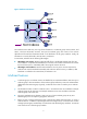
Figure 8 Positions of Layer 3 multicast protocols Receiver AS 1 Receiver IGMP/MLD IGMP/MLD PIM/IPv6 PIM AS 2 PIM/IPv6 PIM MBGP/MSDP IPv6 MBGP IGMP/MLD Receiver Source • Multicast group management protocols: Typically, the Internet Group Management Protocol (IGMP) or Multicast Listener Discovery (MLD) protocol is used between hosts and Layer 3 multicast devices that directly connect to the hosts to define how to establish and maintain their multicast group memberships.
Figure 9 Positions of Layer 2 multicast protocols Source 1 Multicast VLAN /IPv6 Multicast VLAN IGMP Snooping /MLD Snooping PIM Snooping /IPv6 PIM Snooping Receiver Receiver Source 2 Receiver IPv4/IPv6 multicast packets (S1, G1) • IPv4/IPv6 multicast packets (S2, G2) IGMP snooping and MLD snooping: IGMP snooping and MLD snooping run on Layer 2 devices as multicast constraining mechanisms to improve multicast forwarding efficiency.
incoming interface. The RPF check result determines whether the packet will be forwarded or discarded. The RPF check mechanism is the basis for most multicast routing protocols to implement multicast forwarding. For more information about the RPF mechanism, see "Configuring multicast routing and forwarding" and "Configuring IPv6 multicast routing and forwarding." Multicast support for VPNs Multicast support for VPNs refers to multicast applied in VPNs.
Multicast application in VPNs A PE or MCE device that supports multicast for VPNs does the following operations: • Maintains an independent set of multicast forwarding mechanisms for each VPN, including the multicast protocols, PIM neighbor information, and multicast routing table. In a VPN, the device forwards multicast data based on the forwarding table or routing table for that VPN. • Implements the isolation between different VPNs.
Configuring IGMP snooping Overview IGMP snooping runs on a Layer 2 switch as a multicast constraining mechanism to improve multicast forwarding efficiency. It creates Layer 2 multicast forwarding entries from IGMP packets that are exchanged between the hosts and the router. As shown in Figure 11, when IGMP snooping is not enabled, the Layer 2 switch floods multicast packets to all hosts.
Figure 12 IGMP snooping related ports The following describes the ports involved in IGMP snooping: • Router port—Layer 3 multicast device-side port. Layer 3 multicast devices include designated routers (DRs) and IGMP queriers. In Figure 12, Ten-GigabitEthernet 1/0/1 of Switch A and Ten-GigabitEthernet 1/0/1 of Switch B are the router ports. A switch records all its router ports in a router port list.
Timer Description Dynamic member port aging timer When a port dynamically joins a multicast group, the switch starts or resets an aging timer for the port. When the timer expires, the dynamic member port ages out. Expected message before the timer expires Action after the timer expires IGMP membership report. The switch removes the port from the IGMP snooping forwarding table. NOTE: In IGMP snooping, only dynamic ports age out. Static ports never age out.
switch resolves the multicast group address in the report and looks up the ACL. If a match is found to permit the port that received the report to join the multicast group, the switch creates an IGMP snooping forwarding entry for the multicast group and adds the port to the forwarding entry. Otherwise, the switch drops this report, in which case the multicast data for the multicast group is not sent to this port, and the user cannot retrieve the program.
IGMP snooping configuration task list Task at a glance Configuring basic IGMP snooping functions • • • • (Required.) Enabling IGMP snooping (Optional.) Specifying the IGMP snooping version (Optional.) Setting the maximum number of IGMP snooping forwarding entries (Optional.) Configuring parameters for IGMP queries and responses Configuring IGMP snooping port functions • (Optional.) Setting aging timers for dynamic ports • (Optional.) Configuring static ports • (Optional.
Step Command Remarks 1. Enter system view. system-view N/A 2. Enable IGMP snooping globally and enter IGMP-snooping view. igmp-snooping By default, IGMP snooping is disabled. 3. Enable IGMP snooping for specified VLANs. enable vlan vlan-list By default, IGMP snooping is disabled for a VLAN. To enable IGMP snooping for a VLAN in VLAN view: Step Command Remarks 1. Enter system view. system-view N/A 2. Enable IGMP snooping globally and enter IGMP-snooping view.
Step Specify the IGMP snooping version for the specified VLANs 3. Command Remarks version version-number vlan vlan-list The default setting is IGMPv2 snooping. To specify the IGMP snooping version for a VLAN in VLAN view: Step Command Remarks 1. Enter system view. system-view N/A 2. Enter VLAN view. vlan vlan-id N/A 3. Specify the version of IGMP snooping. igmp-snooping version version-number The default setting is IGMPv2 snooping.
Configuring parameters for IGMP queries and responses globally Step Command Remarks 1. Enter system view. system-view N/A 2. Enter IGMP-snooping view. igmp-snooping N/A 3. Set the maximum response time for IGMP general queries. max-response-time interval The default setting is 10 seconds. Set the IGMP last-member query interval. last-member-query-interval interval The default setting is 1 second. 4. Configuring parameters for IGMP queries and responses in a VLAN Step Command Remarks 1.
Setting the aging timers for dynamic ports globally Step Command Remarks 1. Enter system view. system-view N/A 2. Enter IGMP-snooping view. igmp-snooping N/A 3. Set the aging timer for dynamic router ports globally. router-aging-time interval The default setting is 260 seconds. 4. Set the global aging timer for dynamic member ports globally. host-aging-time interval The default setting is 260 seconds. Setting the aging timers for the dynamic ports in a VLAN Step Command Remarks 1.
Step Configure the port as a static router port. 4. Command Remarks igmp-snooping static-router-port vlan vlan-id By default, a port is not a static router port. Enabling IGMP snooping fast-leave processing The IGMP snooping fast-leave processing feature enables the switch to process IGMP leave messages quickly.
Determine the maximum number of multicast groups that a port can join. • Configuring a multicast group filter When you configure a multicast group filter, follow these guidelines: • This configuration is effective on the multicast groups that a port dynamically joins. If you configure the port as a static member port for a multicast group, this configuration is not effective on the multicast group.
Step Command Remarks 2. Enter IGMP-snooping view. igmp-snooping N/A 3. Enable multicast source port filtering. source-deny port interface-list By default, multicast source port filtering is disabled. Configuring multicast source port filtering on a port Step Command Remarks 1. Enter system view. system-view N/A 2. Enter Layer 2 Ethernet interface view. interface interface-type interface-number N/A 3. Enable multicast source port filtering.
Step Command Remarks 2. Enter VLAN view. vlan vlan-id N/A 3. Enable dropping unknown multicast data for the VLAN. igmp-snooping drop-unknown By default, this function is disabled. Unknown multicast data is flooded. Enabling IGMP report suppression After receiving an IGMP report from a multicast group member, a Layer 2 switch forwards the IGMP report to the directly connected Layer 3 device.
Enabling the multicast group replacement function When the number of multicast groups on a switch or a port exceeds the limit: • If the multicast group replacement is enabled, the switch or the port replaces an existing multicast group with a newly joined multicast group. • If the multicast group replacement is disabled, the switch or the port discards IGMP reports that are used for joining a new multicast group.
Task Command Display information about dynamic IGMP snooping forwarding entries (in standalone mode). display igmp-snooping group [ group-address | source-address ] * [ vlan vlan-id ] [ verbose ] [ slot slot-number ] Display information about dynamic IGMP snooping forwarding entries (in IRF mode).
Task Command Remove dynamic router ports. reset igmp-snooping router-port { all | vlan vlan-id } Clear statistics for the IGMP messages learned by IGMP snooping. reset igmp-snooping statistics IGMP snooping configuration examples Group policy configuration example Network requirements As shown in Figure 13, Router A runs IGMPv2 and serves as the IGMP querier. Switch A runs IGMPv2 snooping.
[RouterA-Ten-GigabitEthernet1/0/1] igmp enable [RouterA-Ten-GigabitEthernet1/0/1] quit # Enable PIM-DM on Ten-GigabitEthernet 1/0/2. [RouterA] interface ten-gigabitethernet 1/0/2 [RouterA-Ten-GigabitEthernet1/0/2] pim dm [RouterA-Ten-GigabitEthernet1/0/2] quit 3. Configure Switch A: # Enable IGMP snooping globally.
Static port configuration example Network requirements As shown in Figure 14: • Router A runs IGMPv2 and serves as the IGMP querier. Switch A, Switch B, and Switch C run IGMPv2 snooping. • Host A and host C are permanent receivers of multicast group 224.1.1.1. Configure Ten-GigabitEthernet 1/0/3 and Ten-GigabitEthernet 1/0/5 on Switch C as static member ports for multicast group 224.1.1.1 to enhance the reliability of multicast traffic transmission. • Suppose the STP runs on the network.
# Enable IP multicast routing globally. system-view [RouterA] multicast routing [RouterA-mrib] quit # Enable IGMP on Ten-GigabitEthernet 1/0/1. [RouterA] interface ten-gigabitethernet 1/0/1 [RouterA-Ten-GigabitEthernet1/0/1] igmp enable [RouterA-Ten-GigabitEthernet1/0/1] quit # Enable PIM-DM on Ten-GigabitEthernet 1/0/2. [RouterA] interface ten-gigabitethernet 1/0/2 [RouterA-Ten-GigabitEthernet1/0/2] pim dm [RouterA-Ten-GigabitEthernet1/0/2] quit 3.
[SwitchC-vlan100] port ten-gigabitethernet 1/0/1 to ten-gigabitethernet 1/0/5 [SwitchC-vlan100] igmp-snooping enable [SwitchC-vlan100] quit # Configure Ten-GigabitEthernet 1/0/3 and Ten-GigabitEthernet 1/0/5 as static member ports for multicast group 224.1.1.1. [SwitchC] interface ten-gigabitethernet 1/0/3 [SwitchC-Ten-GigabitEthernet1/0/3] igmp-snooping static-group 224.1.1.
Solution 1. Use the display igmp-snooping command to display IGMP snooping status. 2. If IGMP snooping is not enabled, use the igmp-snooping command in system view to enable IGMP snooping globally, and then use the igmp-snooping enable command in VLAN view to enable IGMP snooping for the VLAN. 3. If IGMP snooping is enabled globally but not enabled for the VLAN, use the igmp-snooping enable command in VLAN view to enable IGMP snooping for the VLAN.
Configuring multicast routing and forwarding Overview The following tables are involved in multicast routing and forwarding: • Multicast routing table of each multicast routing protocol, such as the PIM routing table. • General multicast routing table that summarizes multicast routing information generated by different multicast routing protocols. The multicast routing information from multicast sources to multicast groups are stored in a set of (S, G) routing entries.
priority as the RPF route. If the routes have the same priority, the router selects a route as the RPF route in the order of static multicast route and unicast route. For more information about the route priority, see Layer 3—IP Routing Configuration Guide. { If the router does not use the longest prefix match principle, the router selects the route that has the highest priority as the RPF route.
Figure 15 RPF check process IP Routing Table on Switch C Destination/Mask Interface 192.168.0.0/24 Vlan-int20 Switch B Receiver Vlan-int10 Source 192.168.0.1/24 Switch A Vlan-int10 Receiver Vlan-int20 Multicast packets Switch C As shown in Figure 15, assume that unicast routes are available in the network, and no static multicast routes have been configured on Switch C. A multicast packet (S, G) travels along the SPT from the multicast source to the receivers.
Figure 16 Changing an RPF route Multicast Routing Table Static on Switch C Source/Mask Interface RPF neighbor/Mask 192.168.0.0/24 Vlan-int10 1.1.1.1/24 Switch B Receiver Multicast packets Multicast static route Vlan-int10 1.1.1.1/24 Source Vlan-int10 1.1.1.2/24 Receiver Vlan-int20 192.168.0.
and Switch D, specifying Switch B as the RPF neighbor of Switch C and Switch C as the RPF neighbor of Switch D, the receiver hosts can receive the multicast data from the multicast source. NOTE: A static multicast route is effective only on the multicast router on which it is configured, and will not be advertised throughout the network or redistributed to other routers. Configuration task list Tasks at a glance (Required.) Enabling IP multicast routing (Optional.
Configuring static multicast routes By configuring a static multicast route for a given multicast source, you can specify an RPF interface or an RPF neighbor for the multicast traffic from that source. To configure a static multicast route: Step Command Remarks 1. Enter system view. system-view N/A 2. Configure a static multicast route.
Step Command Remarks 2. Enter MRIB view. multicast routing [ vpn-instance vpn-instance-name ] N/A 3. Configure multicast load splitting. load-splitting { source | source-group } By default, load splitting is disabled. Configuring a multicast forwarding boundary A multicast forwarding boundary sets the boundary condition for the multicast groups in a specific range. The multicast data for a multicast group travels within a definite boundary in a network.
Step 2. Configure a static multicast MAC address entry. Command Remarks mac-address multicast mac-address interface interface-list vlan vlan-id By default, no static multicast MAC address entries exist. To configure a static multicast MAC address entry in interface view: Step Command Remarks 1. Enter system view. system-view N/A 2. Enter Ethernet interface/Layer 2 aggregate interface view. interface interface-type interface-number N/A 3. Configure a static multicast MAC address entry.
Task Command Display multicast forwarding table information (in IRF mode). display multicast [ vpn-instance vpn-instance-name ] forwarding-table [ source-address [ mask { mask-length | mask } ] | group-address [ mask { mask-length | mask } ] | chassis chassis-number slot slot-number | incoming-interface interface-type interface-number | outgoing-interface { exclude | include | match } interface-type interface-number | statistics ] * Display information about the multicast routing table.
Figure 18 Network diagram Configuration procedure 1. Assign an IP address and subnet mask for each interface according to Figure 18. (Details not shown.) 2. Enable OSPF on the switches in the PIM-DM domain to make sure the following conditions are met: (Details not shown.) 3. { The switches are interoperable at the network layer. { The switches can dynamically update their routing information. Enable IP multicast routing, and enable IGMP and PIM-DM: # On Switch B, enable IP multicast routing.
[SwitchA-mrib] quit [SwitchA] interface vlan-interface 200 [SwitchA-Vlan-interface200] pim dm [SwitchA-Vlan-interface200] quit [SwitchA] interface vlan-interface 102 [SwitchA-Vlan-interface102] pim dm [SwitchA-Vlan-interface102] quit [SwitchA] interface vlan-interface 103 [SwitchA-Vlan-interface103] pim dm [SwitchA-Vlan-interface103] quit # Enable IP multicast routing and PIM-DM on Switch C in the same way Switch A is configured. (Details not shown.) 4. Display the RPF route to Source on Switch B.
Configure the switches so that the receiver host receives multicast data from Source 2, which is outside the OSPF domain. Figure 19 Network diagram Configuration procedure 1. Assign an IP address and subnet mask for each interface according to Figure 19. (Details not shown.) 2. Enable OSPF on Switch B and Switch C to make sure the following conditions are met: (Details not shown.) 3. { The switches are interoperable at the network layer.
[SwitchA] interface vlan-interface 102 [SwitchA-Vlan-interface102] pim dm [SwitchA-Vlan-interface102] quit # Enable IP multicast routing and PIM-DM on Switch B in the same way Switch A is configured. (Details not shown.) 4. Display information about their RPF routes to Source 2 on Switch B and Switch C. [SwitchB] display multicast rpf-info 50.1.1.100 [SwitchC] display multicast rpf-info 50.1.1.100 No output is displayed because no RPF routes to the source 2 exist on Switch B or Switch C. 5.
Analysis • If a static multicast route is not correctly configured or updated to match the current network conditions, it does not exist in the static multicast routing table. • If a better route is found, the static multicast route might also fail. 1. Use the display multicast routing-table static command to display information about static multicast routes to verify that the static multicast route has been correctly configured and the route entry exists in the static multicast routing table. 2.
Configuring IGMP Overview Internet Group Management Protocol (IGMP) establishes and maintains the multicast group memberships between a Layer 3 multicast device and its directly connected hosts. IGMP has three versions: • IGMPv1 (defined by RFC 1112) • IGMPv2 (defined by RFC 2236) • IGMPv3 (defined by RFC 3376) All IGMP versions support the ASM model. In addition to the ASM model, IGMPv3 can directly implement the SSM model.
Figure 20 IGMP queries and reports As shown in Figure 20, Host B and Host C are interested in the multicast data addressed to the multicast group G1, and Host A is interested in the multicast data addressed to G2. The following process describes how the hosts join the multicast groups and how the IGMP querier (Router B in Figure 20) maintains the multicast group memberships: 1.
IGMPv2 enhancements Backwards-compatible with IGMPv1, IGMPv2 has introduced a querier election mechanism and a leave-group mechanism. Querier election mechanism In IGMPv1, the DR elected by the Layer 3 multicast routing protocol (such as PIM) serves as the querier among multiple routers that run IGMP on the same subnet. IGMPv2 introduced an independent querier election mechanism. The querier election process is as follows: 1.
• If the host expects to receive multicast data from specific sources like S1, S2, …, it sends a report with the Filter-Mode denoted as "Include Sources (S1, S2, …)." • If the host expects to reject multicast data from specific sources like S1, S2, …, it sends a report with the Filter-Mode denoted as "Exclude Sources (S1, S2, …)". As shown in Figure 21, the network has two multicast sources, Source 1 (S1) and Source 2 (S2). Both of them can send multicast data to the multicast group G.
{ TO_IN—The filtering mode has changed from Exclude to Include. { TO_EX—The filtering mode has changed from Include to Exclude. { { ALLOW—The Source Address fields in this group record contain a list of the additional sources from which the system wants to obtain data for packets sent to the specified multicast address. If the change was to an Include source list, these sources are the addresses that were added to the list.
• Determine the multicast group and multicast source addresses for static group member configuration. • Determine the ACL for multicast group filtering. Enabling IGMP To configure IGMP, enable IGMP on the interface where the multicast group memberships are established and maintained. To enable IGMP: Step Command Remarks 1. Enter system view. system-view N/A 2. Enable IP multicast routing and enter MRIB view.
A static member interface does not respond to queries that the IGMP querier sends. When you configure an interface as a static member or cancel this configuration on the interface, the interface does not send any IGMP report or IGMP leave message without a request. This is because the interface is not a real member of the multicast group or the multicast source and group. • Configuration procedure To configure an interface as a static member interface: Step Command Remarks 1. Enter system view.
Enabling IGMP fast-leave processing In some applications, such as ADSL dial-up networking, only one multicast receiver host is attached to an interface of the IGMP querier. To allow fast response to the leave messages of the host when it switches frequently from one multicast group to another, you can enable fast-leave processing on the IGMP querier.
IGMP configuration examples Network requirements As shown in Figure 22: • VOD streams are sent to receiver hosts in multicast. • Receiver hosts of different organizations form stub networks N1 and N2. Host A and Host C are receiver hosts in N1 and N2, respectively. • IGMPv2 runs between Switch A and N1, and between the other two switches and N2. • Switch A acts as the IGMP querier in N1. Switch B acts as the IGMP querier in N2 because it has a lower IP address.
# On Switch A, enable IP multicast routing. system-view [SwitchA] multicast routing [SwitchA-mrib] quit # Enable IGMP on VLAN-interface 100 (the interface that connects to the stub network). [SwitchA] interface vlan-interface 100 [SwitchA-Vlan-interface100] igmp enable [SwitchA-Vlan-interface100] quit # Enable PIM-DM on VLAN-interface 101. [SwitchA] interface vlan-interface 101 [SwitchA-Vlan-interface101] pim dm [SwitchA-Vlan-interface101] quit # On Switch B, enable IP multicast routing.
Verifying the configuration # Display IGMP information on VLAN-interface 200 of Switch B. [SwitchB] display igmp interface vlan-interface 200 Vlan-interface200(10.110.2.1): IGMP is enabled. IGMP version: 2 Query interval for IGMP: 125s Other querier present time for IGMP: 255s Maximum query response time for IGMP: 10s Querier for IGMP: 10.110.2.
Inconsistent membership information on the routers on the same subnet Symptom Different memberships are maintained on different IGMP routers on the same subnet. Analysis • A router running IGMP maintains multiple parameters for each interface. Inconsistent IGMP interface parameter configurations for routers on the same subnet will result in inconsistency of memberships.
Configuring PIM Overview Protocol Independent Multicast (PIM) provides IP multicast forwarding by leveraging unicast static routes or unicast routing tables generated by any unicast routing protocol, such as RIP, OSPF, IS-IS, or BGP. PIM is not dependent on any particular unicast routing protocol, and it uses the underlying unicast routing to generate a routing table with routes. PIM uses the RPF mechanism to implement multicast forwarding.
• SPT building • Graft • Assert Neighbor discovery In a PIM domain, each interface that runs PIM on a router periodically multicasts PIM hello messages to all other PIM routers (identified by the address 224.0.0.13) on the local subnet to discover PIM neighbors, maintain PIM neighboring relationship with other routers, and build and maintain SPTs. SPT building The process of building an SPT is the flood-and-prune process: 1.
The pruned state of a branch has a finite holdtime timer. When the timer expires, multicast data is again forwarded to the pruned branch. The flood-and-prune cycle takes place periodically to maintain the forwarding branches. Graft To reduce the join latency when a new receiver on a previously pruned branch joins a multicast group, PIM-DM uses a graft mechanism to turn the pruned branch into a forwarding branch, as follows: 1.
PIM-SM overview PIM-DM uses the flood-and-prune cycles to build SPTs for multicast data forwarding. Although an SPT has the shortest paths from the multicast source to the receivers, it is built with a low efficiency and is not suitable for large- and medium-sized networks. PIM-SM uses the pull mode for multicast forwarding, and it is suitable for large- and medium-sized networks with sparsely and widely distributed multicast group members.
IMPORTANT: IGMP must be enabled on the device that acts as the receiver-side DR. Otherwise, the receiver hosts attached to the DR cannot join any multicast groups. Figure 25 DR election As shown in Figure 25, the DR election process is as follows: 1. The routers on the shared-media LAN send hello messages to one another. The hello messages contain the priority for DR election. The router with the highest DR priority is elected as the DR. 2.
BSR encapsulates the RP-set information in the bootstrap messages (BSMs) and floods the BSMs to the entire PIM-SM domain. Figure 26 Information exchange between C-RPs and BSR Based on the information in the RP-set, all routers in the network can select the proper RP for a specific multicast group based on the following rules: 1. The C-RP that is designated to a smallest group range wins. 2. If the C-RPs are designated to the same group range, the C-RP with the highest priority wins. 3.
1. When a receiver wants to join the multicast group G, it uses an IGMP message to inform the receiver-side DR. 2. After getting the receiver information, the DR sends a join message, which is forwarded hop by hop to the RP for the multicast group. 3. The routers along the path from the DR to the RP form an RPT branch. Each router on this branch adds to its forwarding table a (*, G) entry, where the asterisk (*) represents any multicast source.
to the receivers along the RPT. Meanwhile, it unicasts a register-stop message to the source-side DR to prevent the DR from unnecessarily encapsulating the data. Switchover to SPT In a PIM-SM domain, only one RP and one RPT provide services for a specific multicast group. Before the switchover to SPT occurs, the source-side DR encapsulates all multicast data addressed to the multicast group in register messages and sends them to the RP.
Administrative scoping mechanism To implement refined management, you can divide a PIM-SM domain into a global-scoped zone and multiple administratively-scoped zones (admin-scoped zones). This is called the "administrative scoping mechanism." The administrative scoping mechanism effectively releases stress on the management in a single-BSR domain and enables provision of zone-specific services through private group addresses. Admin-scoped zones are divided for multicast groups.
Multicast packets that do not belong to any admin-scoped zones are forwarded in the entire PIM-SM domain. • In view of multicast group address ranges: Each admin-scoped zone is designated to specific multicast groups, of which the multicast group addresses are valid only within the local zone. The multicast groups of different admin-scoped zones might have intersections. All the multicast groups other than those of the admin-scoped zones use the global-scoped zone.
SPT building The decision to build an RPT for PIM-SM or an SPT for PIM-SSM depends on whether the multicast group that the receiver wants to join is included in the SSM group range (232.0.0.0/8 reserved by IANA). Figure 31 SPT building in PIM-SSM As shown in Figure 31, Host B and Host C are receivers. They send IGMPv3 report messages to their DRs to express their interest in the multicast information that the multicast source S sends to the multicast group G.
After receiving a multicast data packet, the multicast router checks to which VPN the data packet belongs, and then forwards the packet according to the multicast routing table for that VPN or creates a multicast routing entry for that VPN.
Step Command Remarks 1. Enter system view. system-view N/A 2. Enable IP multicast routing and enter MRIB view. multicast routing [ vpn-instance vpn-instance-name ] By default, IP multicast routing is disabled. 3. Return to system view. quit N/A 4. Enter interface view. interface interface-type interface-number N/A 5. Enable PIM-DM. pim dm By default, PIM-DM is disabled. Enabling the state refresh feature Pruned interfaces resume multicast forwarding when the pruned state times out.
Step Command Remarks 2. Enter PIM view. pim [ vpn-instance vpn-instance-name ] N/A 3. Configure the interval to send state refresh messages. state-refresh-interval interval The default setting is 60 seconds. 4. Configure the time to wait before receiving a new state refresh message. state-refresh-rate-limit time The default setting is 30 seconds. Configure the TTL value of state refresh messages. state-refresh-ttl ttl-value The default setting 255. 5.
Task at a glance • (Required.) Configuring a C-BSR • (Optional.) Configuring a PIM domain border (Optional.) Disabling the BSM semantic fragmentation function (Optional.) Configuring multicast source registration (Optional.) Configuring switchover to SPT (Optional.) Configuring common PIM features Configuration prerequisites Before you configure PIM-SM, configure a unicast routing protocol so that all devices in the domain are interoperable at the network layer.
Configuring a static RP If only one dynamic RP exists on a network, you can configure a static RP to avoid communication interruption caused by single-point failures. The static RP also prevents frequent message exchange between C-RPs and the BSR for RP election. The static RP configuration must be the same on all routers in the PIM-SM domain. To configure a static RP: Step Command Remarks 1. Enter system view. system-view N/A 2. Enter PIM view. pim [ vpn-instance vpn-instance-name ] N/A 3.
Configuring a BSR You must configure a BSR if C-RPs are configured to dynamically select the RP. In a network with a static RP, this configuration task is unnecessary. A PIM-SM domain can have only one BSR, but must have at least one C-BSR. Any router can be configured as a C-BSR. Elected from C-BSRs, the BSR is responsible for collecting and advertising RP information in the PIM-SM domain. Configuring a C-BSR C-BSRs should be configured on routers on the backbone network.
Step Command Remarks 1. Enter system view. system-view N/A 2. Enter PIM view. pim [ vpn-instance vpn-instance-name ] N/A 3. Configure a C-BSR. c-bsr ip-address [ scope group-address { mask-length | mask } ] [ hash-length hash-length | priority priority ] * By default, no C-BSR is configured. 4. (Optional.) Configure a legal BSR address range. bsr-policy acl-number By default, no restrictions are defined.
Step Command Remarks 1. Enter system view. system-view N/A 2. Enter PIM view. pim [ vpn-instance vpn-instance-name ] N/A 3. Disable the BSM semantic fragmentation function. undo bsm-fragment enable By default, BSM semantic fragmentation is enabled. NOTE: Generally, a BSR performs BSM semantic fragmentation according to the MTU of its BSR interface.
Step Command Remarks 1. Enter system view. system-view N/A 2. Enter PIM view. pim [ vpn-instance vpn-instance-name ] N/A 3. Configure the criteria for triggering a switchover to SPT. spt-switch-threshold { immediacy | infinity } [ group-policy acl-number ] By default, the device immediately triggers a switchover to SPT after receiving the first multicast packet. Configuring PIM-SSM PIM-SSM requires IGMPv3 support. Enable IGMPv3 on PIM routers that connect to multicast receivers.
Step Enable PIM-SM. 5. Command Remarks pim sm By default, PIM-SM is disabled. Configuring the SSM group range When a PIM-SM enabled interface receives a multicast packet, it checks whether the multicast group address of the packet is in the SSM group range. If the multicast group address is in this range, the PIM mode for this packet is PIM-SSM. If the multicast group address is not in this range, the PIM mode is PIM-SM.
• Configure a unicast routing protocol so that all devices in the domain are interoperable at the network layer. • Configure PIM-DM, or PIM-SM. Configuring a multicast data filter In either a PIM-DM domain or a PIM-SM domain, routers can check passing-by multicast data and determine whether to continue forwarding the multicast data based on the configured filtering rules.
Configuring PIM hello message options In either a PIM-DM domain or a PIM-SM domain, hello messages exchanged among routers contain the following configurable options: • DR_Priority (for PIM-SM only)—Priority for DR election. The device with the highest priority wins the DR election. You can configure this option for all the routers in a shared-media LAN that directly connects to the multicast source or the receivers. • Holdtime—PIM neighbor lifetime.
Step Command Remarks 6. Set the override interval. hello-option override-interval interval The default setting is 2500 milliseconds. 7. Enable the neighbor tracking function. hello-option neighbor-tracking By default, the neighbor tracking function is disabled. Configuring hello message options on an interface Step Command Remarks 1. Enter system view. system-view N/A 2. Enter interface view. interface interface-type interface-number N/A 3. Set the DR priority.
current interface. If you configure common PIM timers in both PIM view and interface view, the configuration in interface view always takes precedence. TIP: For a network without special requirements, HP recommends that you use the defaults. Configuring common PIM timers globally Step Command Remarks 1. Enter system view. system-view N/A 2. Enter PIM view. pim [ vpn-instance vpn-instance-name ] N/A 3. Set the interval to send hello messages.
Step Command Remarks 1. Enter system view. system-view N/A 2. Enter PIM view. pim [ vpn-instance vpn-instance-name ] N/A 3. Set the maximum size of each join or prune message. jp-pkt-size size The default setting is 8100 bytes. Enabling BFD for PIM PIM uses hello messages to elect a DR for a shared-media network. The elected DR is the only multicast forwarder on the shared-media network. If the DR fails, a new DR election process will start after the DR ages out.
Task Command Display PIM neighbor information. display pim [ vpn-instance vpn-instance-name ] neighbor [ neighbor-address | interface interface-type interface-number | verbose ] * Display PIM routing table information.
Figure 32 Network diagram Table 6 Interface and IP address assignment Device Interface IP address Switch A VLAN-interface 100 10.110.1.1/24 Switch A VLAN-interface 103 192.168.1.1/24 Switch B VLAN-interface 200 10.110.2.1/24 Switch B VLAN-interface 101 192.168.2.1/24 Switch C VLAN-interface 200 10.110.2.2/24 Switch C VLAN-interface 102 192.168.3.1/24 Switch D VLAN-interface 300 10.110.5.1/24 Switch D VLAN-interface 103 192.168.1.2/24 Switch D VLAN-interface 101 192.168.2.
system-view [SwitchA] multicast routing [SwitchA-mrib] quit # Enable IGMP on VLAN-interface 100 (the interface that connects to the stub network). [SwitchA] interface vlan-interface 100 [SwitchA-Vlan-interface100] igmp enable [SwitchA-Vlan-interface100] quit # Enable PIM-DM on VLAN-interface 103.
Assume that Host A needs to receive the information addressed to multicast group 225.1.1.1. After multicast source 10.110.5.100/24 sends multicast packets to the multicast group, an SPT is established through traffic flooding. Switches on the SPT path (Switch A and Switch D) have their (S, G) entries. Host A sends an IGMP report to Switch A to join the multicast group G, and a (*, G) entry is generated on Switch A.
PIM-SM non-scoped zone configuration example Network requirements As shown in Figure 33: • VOD streams are sent to receiver hosts in multicast. The receivers of different subnets form stub networks, and at least one receiver host exist in each stub network. The entire PIM-SM domain contains only one BSR. • Host A and Host C are multicast receivers in two stub networks N1 and N2. • Both VLAN-interface 105 on Switch D and VLAN-interface 102 on Switch E act as C-BSRs and C-RPs.
Device Interface IP address Switch C VLAN-interface 104 192.168.3.1/24 Switch D VLAN-interface 300 10.110.5.1/24 Switch D VLAN-interface 101 192.168.1.2/24 Switch D VLAN-interface 105 192.168.4.2/24 Switch E VLAN-interface 104 192.168.3.2/24 Switch E VLAN-interface 103 192.168.2.2/24 Switch E VLAN-interface 102 192.168.9.2/24 Switch E VLAN-interface 105 192.168.4.1/24 Configuration procedure 1. Assign an IP address and subnet mask to each interface according to Figure 33.
# Configure VLAN-interface 105 as a C-BSR and a C-RP, and set the hash mask length to 32 and the priority of the C-BSR to 10. [SwitchD] pim [SwitchD-pim] c-bsr 192.168.4.2 hash-length 32 priority 10 [SwitchD-pim] c-rp 192.168.4.2 group-policy 2005 [SwitchD-pim] quit # On Switch E, configure the service scope of RP advertisements. system-view [SwitchE] acl number 2005 [SwitchE-acl-basic-2005] rule permit source 225.1.1.0 0.0.0.
[SwitchE] display pim bsr-info Scope: non-scoped State: Elected Bootstrap timer: 00:01:44 Elected BSR address: 192.168.9.2 Priority: 20 Hash mask length: 32 Uptime: 00:01:18 Candidate BSR address: 192.168.9.2 Priority: 20 Hash mask length: 32 # Display RP information on Switch A. [SwitchA] display pim rp-info BSR RP information: Scope: non-scoped Group/MaskLen: 225.1.1.0/24 RP address Priority HoldTime Uptime Expires 192.168.4.2 192 150 00:51:45 00:02:22 192.168.9.
Figure 34 Network diagram Table 8 Interface and IP address assignment Device Interface IP address Device Interface IP address Switch A Vlan-int100 192.168.1.1/24 Switch D Vlan-int105 10.110.5.2/24 Switch A Vlan-int101 10.110.1.1/24 Switch D Vlan-int108 10.110.7.1/24 Switch B Vlan-int200 192.168.2.1/24 Switch D Vlan-int107 10.110.8.1/24 Switch B Vlan-int101 10.110.1.2/24 Switch E Vlan-int400 192.168.4.1/24 Switch B Vlan-int103 10.110.2.1/24 Switch E Vlan-int104 10.110.4.
Configuration procedure 1. Assign an IP address and subnet mask to each interface according to Figure 34. (Details not shown.) 2. Enable OSPF on all switches on the PIM-SM network to make sure the following conditions are met: (Details not shown.) 3. { The switches are interoperable at the network layer. { The switches can dynamically update their routing information. Enable IP multicast routing, and enable IGMP and PIM-SM: # On Switch A, enable IP multicast routing.
[SwitchB] interface vlan-interface 103 [SwitchB-Vlan-interface103] multicast boundary 239.0.0.0 8 [SwitchB-Vlan-interface103] quit # On Switch C, configure VLAN-interface 103 and VLAN-interface 106 as the boundaries of admin-scoped zone 2. system-view [SwitchC] interface vlan-interface 103 [SwitchC-Vlan-interface103] multicast boundary 239.0.0.0 8 [SwitchC-Vlan-interface103] quit [SwitchC] interface vlan-interface 106 [SwitchC-Vlan-interface106] multicast boundary 239.0.0.
State: Accept Preferred Bootstrap timer: 00:01:44 Elected BSR address: 10.110.9.1 Priority: 64 Hash mask length: 30 Uptime: 00:01:45 Scope: 239.0.0.0/8 State: Elected Bootstrap timer: 00:00:06 Elected BSR address: 10.110.1.2 Priority: 64 Hash mask length: 30 Uptime: 00:04:54 Candidate BSR address: 10.110.1.2 Priority: 64 Hash mask length: 30 # Display BSR information on Switch D. [SwitchD] display pim bsr-info Scope: non-scoped State: Accept Preferred Bootstrap timer: 00:01:44 Elected BSR address: 10.110.
Hash mask length: 30 # Display RP information on Switch B. [SwitchB] display pim rp-info BSR RP information: Scope: non-scoped Group/MaskLen: 224.0.0.0/4 RP address Priority HoldTime Uptime Expires 10.110.9.1 192 150 00:03:39 00:01:51 RP address Priority HoldTime Uptime Expires 10.110.1.2 (local) 192 150 00:07:44 00:01:51 RP address Priority HoldTime Uptime Expires 10.110.9.1 192 150 00:03:42 00:01:48 RP address Priority HoldTime Uptime Expires 10.110.5.
Figure 35 Network diagram Table 9 Interface and IP address assignment Device Interface IP address Switch A VLAN-interface 100 10.110.1.1/24 Switch A VLAN-interface 101 192.168.1.1/24 Switch A VLAN-interface 102 192.168.9.1/24 Switch B VLAN-interface 200 10.110.2.1/24 Switch B VLAN-interface 103 192.168.2.1/24 Switch C VLAN-interface 200 10.110.2.2/24 Switch C VLAN-interface 104 192.168.3.1/24 Switch D VLAN-interface 300 10.110.5.1/24 Switch D VLAN-interface 101 192.168.1.
2. 3. Configure OSPF on the switches in the PIM-SSM domain to make sure the following conditions are met: (Details not shown.) { The switches are interoperable at the network layer. { The switches can dynamically update their routing information. Enable IP multicast routing, IGMP, and PIM-SM: # On Switch A, enable IP multicast routing. system-view [SwitchA] multicast routing [SwitchA-mrib] quit # Enable IGMPv3 on VLAN-interface 100 (the interface that connects to the stub network).
the SPT path (Switch A and Switch D) have generated an (S, G) entry, but Switch E, which is not on the SPT path, does not have multicast routing entries. You can use the display pim routing-table command to display the PIM routing table information on each switch. For example: # Display PIM routing table information on Switch A. [SwitchA] display pim routing-table Total 0 (*, G) entry; 1 (S, G) entry (10.110.5.100, 232.1.1.
• On a PIM-SM enabled network, when a router wants to join the SPT, the router creates an (S, G) entry only if it has a route to the multicast source. If the router does not have a route to the multicast source, or if PIM-SM is not enabled on the RPF interface toward the multicast source, the router cannot create an (S, G) entries. • When a multicast router receives a multicast packet, it looks up the existing unicast routing table for the optimal route to the packet source.
Solution 1. Use display current-configuration to verify the multicast forwarding boundary settings. Use multicast boundary to change the multicast forwarding boundary settings to make the multicast packet able to cross the boundary. 2. Use display current-configuration to verify the multicast data filter. Change the ACL rule defined in the source-policy command so that the source/group address of the multicast data can pass ACL filtering.
Solution 1. Use display ip routing-table to verify that unicast routes to the C-RPs and the BSR are available on each router and that a route is available between each C-RP and the BSR. Make sure each C-RP has a unicast route to the BSR, the BSR has a unicast route to each C-RP, and each router on the network has unicast routes to the C-RPs. 2.
Configuring MLD snooping Overview MLD snooping runs on a Layer 2 switch as an IPv6 multicast constraining mechanism to improve multicast forwarding efficiency. It creates Layer 2 multicast forwarding entries from MLD messages that are exchanged between the hosts and the router. As shown in Figure 36, when MLD snooping is not enabled, the Layer 2 switch floods IPv6 multicast packets to all hosts.
Figure 37 MLD snooping related ports The following describes the ports involved in MLD snooping, as shown in Figure 37: • Router port—Layer 3 multicast device-side port. Layer 3 multicast devices include designated routers and MLD queriers. In Figure 37, Ten-GigabitEthernet 1/0/1 of Switch A and Ten-GigabitEthernet 1/0/1 of Switch B are the router ports. A switch records all its local router ports in a router port list.
NOTE: In MLD snooping, only dynamic ports age out. Static ports never age out. How MLD snooping works The ports in this section are dynamic ports. For information about how to configure and remove static ports, see "Configuring static ports." MLD messages include general query, MLD report, and done message. An MLD snooping-enabled switch performs differently depending on the MLD message.
determine whether the reported IPv6 multicast group still has active members attached to that port. For more information about the MLD report suppression mechanism, see "Configuring MLD." Done message When a host leaves an IPv6 multicast group, the host sends an MLD done message to the multicast routers.
MLD snooping configuration task list Task at a glance Configuring basic MLD snooping functions • • • • (Required.) Enabling MLD snooping (Optional.) Specifying the MLD snooping version (Optional.) Setting the maximum number of MLD snooping forwarding entries (Optional.) Configuring parameters for MLD queries and responses Configuring MLD snooping port functions • (Optional.) Setting aging timers for dynamic ports • (Optional.) Configuring static ports • (Optional.
Step Command Remarks 1. Enter system view. system-view N/A 2. Enable MLD snooping globally and enter MLD-snooping view. mld-snooping By default, MLD snooping is disabled. Enable MLD snooping for the specified VLANs. enable vlan vlan-list By default, MLD snooping is disabled for a VLAN. 3. To enable MLD snooping for a VLAN in VLAN view: Step Command Remarks 1. Enter system view. system-view N/A 2. Enable MLD snooping globally and enter MLD-snooping view.
Step Specify the IGMP snooping version for the specified VLANs 3. Command Remarks version version-number vlan vlan-list The default setting is MLDv1 snooping. To specify the MLD snooping version for a VLAN in VLAN view: Step Command Remarks 1. Enter system view. system-view N/A 2. Enter VLAN view. vlan vlan-id N/A 3. Specify the version of MLD snooping. mld-snooping version version-number The default setting is MLDv1 snooping.
Configuring parameters for MLD queries and responses globally Step Command Remarks 1. Enter system view. system-view N/A 2. Enter MLD-snooping view. mld-snooping N/A 3. Set the maximum response delay for MLD general queries. max-response-time interval The default setting is 10 seconds. Set the MLD last-listener query interval. last-listener-query-interval interval The default setting is 1 second. 4. Configuring parameters for MLD queries and responses in a VLAN Step Command Remarks 1.
Setting the aging timers for dynamic ports globally Step Command Remarks 1. Enter system view. system-view N/A 2. Enter MLD-snooping view. mld-snooping N/A 3. Set the aging timer for dynamic router ports globally. router-aging-time interval The default setting is 260 seconds. 4. Set the aging timer for dynamic member ports globally. host-aging-time interval The default setting is 260 seconds. Setting the aging timers for the dynamic ports in a VLAN Step Command Remarks 1.
Step Command Remarks 3. Configure the port as a static member port. mld-snooping static-group ipv6-group-address [ source-ip ipv6-source-address ] vlan vlan-id By default, a port is not a static member port. 4. Configure the port as a static router port. mld-snooping static-router-port vlan vlan-id By default, a port is not a static router port. Enabling MLD snooping fast-leave processing The MLD snooping fast-leave processing feature enables the switch to process MLD done messages quickly.
• Enable MLD snooping for the VLAN. • Determine the ACL used as the IPv6 multicast group filter. • Determine the maximum number of IPv6 multicast groups that a port can join. Configuring an IPv6 multicast group filter When you configure an IPv6 multicast group filter, follow these guidelines: • This configuration takes effect for the IPv6 multicast groups that the port dynamically joins.
Configuring IPv6 multicast source port filtering globally Step Command Remarks 1. Enter system view. system-view N/A 2. Enter MLD-snooping view. mld-snooping N/A 3. Enable IPv6 multicast source port filtering. source-deny port interface-list By default, the IPv6 multicast source port filtering is disabled. Configuring IPv6 multicast source port filtering on a port Step Command Remarks 1. Enter system view. system-view N/A 2. Enter Layer 2 Ethernet interface view.
Step Command Remarks 1. Enter system view. system-view N/A 2. Enter VLAN view. vlan vlan-id N/A 3. Enable dropping unknown IPv6 multicast data for the VLAN mld-snooping drop-unknown By default, this function is disabled. Unknown IPv6 multicast data is flooded. Enabling MLD report suppression After receiving an MLD report from an IPv6 multicast group member, a Layer 2 switch forwards the MLD report to the directly connected Layer 3 device.
Step Set the maximum number of IPv6 multicast groups on a port. 3. Command Remarks mld-snooping group-limit limit [ vlan vlan-list ] The default setting is 4294967295. Enabling the IPv6 multicast group replacement function When the number of IPv6 multicast groups on a switch or a port exceeds the limit: • If the IPv6 multicast group replacement is enabled, the switch or the port replaces an existing IPv6 multicast group with a newly joined IPv6 multicast group.
Displaying and maintaining MLD snooping Execute display commands in any view and reset commands in user view. Task Command Display information about Layer 2 IPv6 multicast groups (in standalone mode). display ipv6 l2-multicast ip [ group ipv6-group-address | source ipv6-source-address ] * [ vlan vlan-id ] [ slot slot-number ] Display information about Layer 2 IPv6 multicast groups (in IRF mode).
Task Command Display information about static router ports (in standalone mode). display mld-snooping static-router-port [ vlan vlan-id ] [ slot slot-number ] Display information about static router ports (in IRF mode). display mld-snooping static-router-port [ vlan vlan-id ] [ chassis chassis-number slot slot-number ] Display statistics for the MLD messages learned by MLD snooping. display mld-snooping statistics Remove the dynamic MLD snooping forwarding entries for the specified multicast groups.
Configuration procedure 1. Assign an IPv6 address and prefix length to each interface according to Figure 38. (Details not shown.) 2. Configure Router A: # Enable IPv6 multicast routing. system-view [RouterA] ipv6 multicast routing [RouterA-mrib6] quit # Enable MLD on Ten-GigabitEthernet 1/0/1. [RouterA] interface ten-gigabitethernet 1/0/1 [RouterA-Ten-GigabitEthernet1/0/1] mld enable [RouterA-Ten-GigabitEthernet1/0/1] quit # Enable IPv6 PIM-DM on Ten-GigabitEthernet 1/0/2.
(::, FF1E::101) Host slots (1 in total): 1 Host ports (2 in total): XGE1/0/3 XGE1/0/4 The output shows that Host A and Host B have joined the IPv6 multicast group FF1E::101 (through the member ports Ten-GigabitEthernet 1/0/4 and Ten-GigabitEthernet 1/0/3 on Switch A, respectively), but the hosts have failed to join the multicast group FF1E::202.
Figure 39 Network diagram Configuration procedure 1. Assign an IPv6 address and prefix length to each interface according to Figure 39. (Details not shown.) 2. Configure Router A: # Enable IPv6 multicast routing. system-view [RouterA] ipv6 multicast routing [RouterA-mrib6] quit # Enable MLD on Ten-GigabitEthernet 1/0/1.
[SwitchA-vlan100] quit # Configure Ten-GigabitEthernet 1/0/3 as a static router port. [SwitchA] interface ten-gigabitethernet 1/0/3 [SwitchA-Ten-GigabitEthernet1/0/3] mld-snooping static-router-port vlan 100 [SwitchA-Ten-GigabitEthernet1/0/3] quit 4. Configure Switch B: # Enable MLD snooping globally. system-view [SwitchB] mld-snooping [SwitchB-mld-snooping] quit # Create VLAN 100, assign Ten-GigabitEthernet 1/0/1 and Ten-GigabitEthernet 1/0/2 to the VLAN, and enable MLD snooping for the VLAN.
The output shows that Ten-GigabitEthernet 1/0/3 on Switch A has become a static router port. # Display information about the static MLD snooping forwarding entries in VLAN 100 on Switch C. [SwitchC] display mld-snooping static-group vlan 100 Total 1 entries). VLAN 100: Total 1 entries).
Solution 1. Use the display acl ipv6 command to verify that the configured IPv6 ACL meets the IPv6 multicast group filter requirements. 2. Use the display this command in MLD-snooping view or in a corresponding interface view to verify that the correct IPv6 multicast group filter has been applied. If not, use the group-policy or mld-snooping group-policy command to apply the correct IPv6 multicast group filter. 3.
Configuring IPv6 multicast routing and forwarding Overview IPv6 multicast routing and forwarding uses the following tables: • IPv6 multicast protocols' routing tables, such as the IPv6 PIM routing table. • General IPv6 multicast routing table that summarizes the multicast routing information generated by different IPv6 multicast routing protocols. The IPv6 multicast routing information from IPv6 multicast sources to IPv6 multicast groups are stored in a set of (S, G) routing entries.
RPF check implementation in IPv6 multicast Implementing an RPF check on each received IPv6 multicast packet would heavily burden the router. The IPv6 multicast forwarding table is the solution to this issue. When the router creates an IPv6 multicast routing entry and an IPv6 multicast forwarding entry for an IPv6 multicast packet, it sets the RPF interface of the packet as the incoming interface of the forwarding entry.
searches its IPv6 unicast routing table and finds that the outgoing interface to the source (the RPF interface) is VLAN-interface 20. This means that the (S, G) entry is correct but the packet traveled along a wrong path. The RPF check fails and the router discards the packet. Configuration task list Tasks at a glance (Required.) Enabling IPv6 multicast routing (Optional.) Configuring IPv6 multicast routing and forwarding • • • • (Optional.) Configuring the RPF route selection rule (Optional.
Step Command Remarks 2. Enter IPv6 MRIB view. ipv6 multicast routing [ vpn-instance vpn-instance-name ] N/A 3. Configure the device to select the RPF route based on the longest prefix match. longest-match By default, the route with the highest priority is selected as the RPF route. Configuring IPv6 multicast load splitting By configuring per-source or per-source-and-group load splitting, you can optimize the traffic delivery when multiple IPv6 multicast data streams are handled.
Configuring IPv6 static multicast MAC address entries In Layer-2 multicast, a Layer-2 IPv6 multicast protocol (such as MLD snooping) can dynamically add IPv6 multicast MAC address entries. Or, you can manually configure IPv6 multicast MAC address entries. TIP: • You do not need to enable IPv6 multicast routing before this configuration. • The IPv6 multicast MAC address that can be configured in a MAC address entry must be unused.
Task Command Display information about the interfaces maintained by the IPv6 MRIB. display ipv6 mrib [ vpn-instance vpn-instance-name ] interface [ interface-type interface-number ] Display IPv6 multicast boundary information. display ipv6 multicast [ vpn-instance vpn-instance-name ] boundary { group [ ipv6-group-address [ prefix-length ] ] | scope [ scope-id ] } [ interface interface-type interface-number ] Display statistics for IPv6 multicast forwarding events (in standalone mode).
Configuring MLD Overview Multicast Listener Discovery (MLD) establishes and maintains IPv6 multicast group memberships between a Layer 3 multicast device and its directly connected hosts. MLD has two versions: • MLDv1 (defined by RFC 2710), which is derived from IGMPv2. • MLDv2 (defined by RFC 3810), which is derived from IGMPv3. The two MLD versions support the ASM model.
Joining an IPv6 multicast group Figure 41 MLD queries and reports As shown in Figure 41, assume that Host B and Host C want to receive the IPv6 multicast data addressed to IPv6 multicast group G1, and Host A wants to receive the IPv6 multicast data addressed to G2. The following process describes how the hosts join the IPv6 multicast groups and how the MLD querier (Router B in Figure 41) maintains the IPv6 multicast group memberships: 1.
1. The host sends an MLD done message (with the destination of FF02::2) to all IPv6 multicast routers on the local subnet. 2. After receiving the MLD done message, the querier sends a configurable number of multicast-address-specific queries to the group that the host is leaving. The IPv6 multicast addresses queried include both the destination address field and the group address field of the message. 3.
When MLDv2 runs on the hosts and routers, Host B can explicitly express its interest in the IPv6 multicast data that Source 1 sends to G (denoted as (S1, G)), rather than the IPv6 multicast data that Source 2 sends to G (denoted as (S2, G)). Only IPv6 multicast data from Source 1 is delivered to Host B. Enhancement in MLD state A multicast router that is running MLDv2 maintains the multicast address state for each multicast address on each attached subnet.
Determine the ACL rule for IPv6 multicast group filtering. • Enabling MLD Enable MLD on the interface on which IPv6 multicast group memberships are created and maintained. To enable MLD: Step Command Remarks 1. Enter system view. system-view N/A 2. Enable IPv6 multicast routing and enter IPv6 MRIB view. ipv6 multicast routing [ vpn-instance vpn-instance-name ] Disable by default. 3. Return to system view. quit N/A 4. Enter interface view. interface interface-type interface-number N/A 5.
does not send any MLD report or an MLD done message without a request. This is because the interface is not a real member of the IPv6 multicast group or the IPv6 multicast source and group. Configuration procedure To configure an interface as a static member interface: Step Command Remarks 1. Enter system view. system-view N/A 2. Enter interface view. interface interface-type interface-number N/A 3. Configure the interface as a static member interface.
Enabling MLD fast-leave processing In some applications, such as ADSL dial-up networking, only one multicast receiver host is attached to an interface of the MLD querier. To allow fast response to the MLD done messages of the host when it switches frequently from one IPv6 multicast group to another, you can enable fast-leave processing on the MLD querier.
• VOD streams are sent to receiver hosts in multicast. Receiver hosts of different organizations form stub networks N1 and N2. Host A and Host C are multicast receiver hosts in N1 and N2, respectively. • MLDv1 runs between Switch A and N1, and between the other two switches (Switch B and Switch C) and N2. • Switch A acts as the MLD querier in N1. Switch B acts as the MLD querier in N2 because it has a lower IPv6 address.
[SwitchA-Vlan-interface100] mld enable [SwitchA-Vlan-interface100] quit # Enable IPv6 PIM-DM on VLAN-interface 101. [SwitchA] interface vlan-interface 101 [SwitchA-Vlan-interface101] ipv6 pim dm [SwitchA-Vlan-interface101] quit # On Switch B, enable IPv6 multicast routing. system-view [SwitchB] ipv6 multicast routing [SwitchB-mrib6] quit # Enable MLD on VLAN-interface 200 (the interface that connects to the stub network).
Query interval for MLD: 125s Other querier present time for MLD: 255s Maximum query response time for MLD: 10s Querier for MLD: FE80::200:5EFF:FE66:5100 (This router) MLD groups reported in total: 1 Troubleshooting MLD No member information exists on the receiver-side router Symptom When a host sends a message to announce its joining IPv6 multicast group G, no member information of multicast group G exists on the immediate router.
Analysis • A router running MLD maintains multiple parameters for each interface. Inconsistent MLD interface parameter configurations for routers on the same subnet result in inconsistent MLD memberships. • Although routers are partially compatible with hosts that separately run different versions of MLD, all routers on the same subnet must run the same MLD version. Inconsistent MLD versions running on routers on the same subnet lead to inconsistent MLD memberships. 1.
Configuring IPv6 PIM PIM overview Protocol Independent Multicast for IPv6 (IPv6 PIM) provides IPv6 multicast forwarding by leveraging IPv6 unicast static routes or IPv6 unicast routing tables generated by any IPv6 unicast routing protocol, such as RIPng, OSPFv3, IPv6 IS-IS, or IPv6 BGP. IPv6 PIM is not dependent on any particular IPv6 unicast routing protocol, and it uses the underlying IPv6 unicast routing to generate a routing table with routes.
• Neighbor discovery • SPT building • Graft • Assert Neighbor discovery In an IPv6 PIM domain, each interface that runs IPv6 PIM on a router periodically multicasts IPv6 PIM hello messages to all other IPv6 PIM routers on the local subnet to discover IPv6 PIM neighbors, maintain IPv6 PIM neighboring relationship with other routers, and build and maintain SPTs. SPT building The process of building an SPT is the flood-and-prune process: 1.
The pruned state of a branch has a finite holdtime timer. When the timer expires, IPv6 multicast data is again forwarded to the pruned branch. The flood-and-prune cycle takes place periodically to maintain the forwarding branches. Graft To reduce the join latency when a new receiver on a previously pruned branch joins an IPv6 multicast group, IPv6 PIM-DM uses a graft mechanism to turn the pruned branch into a forwarding branch, as follows: 1.
IPv6 PIM-SM overview IPv6 PIM-DM uses the flood-and-prune cycles to build SPTs for IPv6 multicast data forwarding. Although an SPT has the shortest paths from the IPv6 multicast source to the receivers, it is built with a low efficiency and is not suitable for large- and medium-sized networks. IPv6 PIM-SM uses the pull mode for IPv6 multicast forwarding, and it is suitable for large-sized and medium-sized networks with sparsely and widely distributed IPv6 multicast group members.
IMPORTANT: MLD must be enabled on the device that acts as the receiver-side DR. Otherwise, the receiver hosts attached to the DR cannot join any IPv6 multicast groups. For more information about MLD, see "Configuring MLD." Figure 46 DR election As shown in Figure 25, the DR election process is as follows: 1. The routers on the shared-media LAN send hello messages to one another. The hello messages contain the priority for DR election. The router with the highest DR priority is elected as the DR. 2.
As shown in Figure 26, each C-RP periodically unicasts its advertisement messages (C-RP-Adv messages) to the BSR. An advertisement message contains the address of the advertising C-RP and the IPv6 multicast group range to which it is designated. The BSR collects these advertisement messages and organizes the C-RP information into an RP-set, which is a database of mappings between IPv6 multicast groups and RPs.
RPT building Figure 48 RPT building in an IPv6 PIM-SM domain As shown in Figure 27, the process of building an RPT is as follows: 1. When a receiver wants to join the IPv6 multicast group G, it uses an MLD message to inform the receiver-side DR. 2. After getting the receiver information, the DR sends a join message, which is forwarded hop by hop to the RP for the IPv6 multicast group. 3. The routers along the path from the DR to the RP form an RPT branch.
Figure 49 IPv6 multicast source registration Host A Source DR Receiver RP Host B Server Receiver SPT Join message Register message Host C IPv6 multicast packets As shown in Figure 28, the IPv6 multicast source registers with the RP as follows: 1. The IPv6 multicast source S sends the first multicast packet to the IPv6 multicast group G.
multicast source constitute an SPT. The subsequent IPv6 multicast data is forwarded to the RP along the SPT without being encapsulated into register messages. For more information about the switchover to SPT initiated by the RP, see "Multicast source registration." • The receiver-side DR initiates a switchover to SPT: After receiving the first (S, G) multicast packet, the receiver-side DR initiates a switchover to SPT immediately, as follows: a.
Relationship between IPv6 admin-scoped zones and the IPv6 global-scoped zone The IPv6 global-scoped zone and each IPv6 admin-scoped zone have their own C-RPs and BSRs. These devices are effective only on their respective zones, and the BSR election and the RP election are implemented independently. Each IPv6 admin-scoped zone has its own boundary. The IPv6 multicast information within a zone cannot cross this boundary in either direction.
Table 10 Values of the Scope field Value Meaning Remarks 0, F Reserved N/A 1 Interface-local scope N/A 2 Link-local scope N/A 3 Subnet-local scope IPv6 admin-scoped zone. 4 Admin-local scope IPv6 admin-scoped zone. 5 Site-local scope IPv6 admin-scoped zone. 6, 7, 9 through D Unassigned IPv6 admin-scoped zone. 8 Organization-local scope IPv6 admin-scoped zone. E Global scope IPv6 global-scoped zone. IPv6 PIM-SSM overview The ASM model includes IPv6 PIM-DM and IPv6 PIM-SM.
Figure 52 SPT building in IPv6 PIM-SSM As shown in Figure 31, Host B and Host C are receivers. They send MLDv2 report messages to their DRs to express their interest in the multicast information that the IPv6 multicast source S sends to the IPv6 multicast group G. After receiving a report message, the DR first checks whether the group address in the message is in the IPv6 SSM group range and does the following: • If the group address is in the IPv6 SSM group range, the IPv6 PIM-SSM service is provided.
• RFC 5059, Bootstrap Router (BSR) Mechanism for Protocol Independent Multicast (PIM) • RFC 4607, Source-Specific Multicast for IP • Draft-ietf-ssm-overview-05, An Overview of Source-Specific Multicast (SSM) Configuring IPv6 PIM-DM This section describes how to configure IPv6 PIM-DM. IPv6 PIM-DM configuration task list Task at a glance (Required.) Enabling PIM-SM (Optional.) Enabling the state refresh feature (Optional.) Configuring state refresh parameters (Optional.
Step 5. Enable IPv6 PIM-DM. Command Remarks ipv6 pim dm By default, IPv6 PIM-DM is disabled. Enabling the state refresh feature Pruned interfaces resume multicast forwarding when the pruned state times out. To prevent this, the router directly connected with the IPv6 multicast source periodically sends an (S, G) state refresh message, which is forwarded hop-by-hop along the initial flooding path of the IPv6 PIM-DM domain, to refresh the prune timer state of all the routers on the path.
Step 4. 5. Command Remarks Configure the time to wait before receiving a new state refresh message. state-refresh-rate-limit time By default, the waiting time is 30 seconds. Configure the hop limit value of state refresh messages. state-refresh-hoplimit hoplimit-value By default, the hop limit value of state refresh messages is 255. Configuring IPv6 PIM-DM graft retry timer In IPv6 PIM-DM, only the graft process uses the acknowledgment mechanism.
Task at a glance (Optional.) Configuring multicast source registration (Optional.) Configuring switchover to SPT (Optional.) Configuring common IPv6 PIM features Configuration prerequisites Before you configure IPv6 PIM-SM, configure an IPv6 unicast routing protocol so that all devices in the domain are interoperable at the network layer. Enabling IPv6 PIM-SM Enable IPv6 multicast routing before configuring IPv6 PIM.
Configuring a static RP If only one dynamic RP exists on a network, you can configure a static RP to avoid communication interruption caused by single-point failures. The static RP also prevents frequent message exchange between C-RPs and the BSR. The static RP configuration must be the same on all routers in the IPv6 PIM-SM domain. To configure a static RP: Step Command Remarks 1. Enter system view. system-view N/A 2. Enter IPv6 PIM view. ipv6 pim [ vpn-instance vpn-instance-name ] N/A 3.
Configuring a BSR You must configure a BSR if C-RPs are configured to dynamically select the RP. In a network with a static RP, this configuration task is unnecessary. An IPv6 PIM-SM domain can have only one BSR, but must have at least one C-BSR. Any router can be configured as a C-BSR. Elected from C-BSRs, the BSR is responsible for collecting and advertising RP information in the IPv6 PIM-SM domain. Configuring a C-BSR C-BSRs should be configured on routers on the backbone network.
Step Command Remarks 2. Enter IPv6 PIM view. ipv6 pim [ vpn-instance vpn-instance-name ] N/A 3. Configure a C-BSR. c-bsr ipv6-address [ scope scope-id ] [ hash-length hash-length | priority priority ] * By default, no C-BSR is configured. 4. (Optional.) Configure a legal BSR address range. bsr-policy acl6-number By default, no restrictions are defined.
Step Command Remarks 1. Enter system view. system-view N/A 2. Enter IPv6 PIM view. ipv6 pim [ vpn-instance vpn-instance-name ] N/A 3. Disable the BSM semantic fragmentation function. undo bsm-fragment enable By default, BSM semantic fragmentation is enabled. NOTE: Generally, a BSR performs BSM semantic fragmentation according to the MTU of its BSR interface.
Step Command Remarks 1. Enter system view. system-view N/A 2. Enter IPv6 PIM view. ipv6 pim [ vpn-instance vpn-instance-name ] N/A 3. Configure the criteria for triggering a switchover to SPT. spt-switch-threshold { immediacy | infinity } [ group-policy acl6-number ] By default, the device immediately triggers a switchover to SPT after receiving the first multicast packet. Configuring IPv6 PIM-SSM IPv6 PIM-SSM requires MLDv2 support.
Step Command Remarks 3. Return to system view. quit N/A 4. Enter interface view. interface interface-type interface-number N/A 5. Enable IPv6 PIM-SM. ipv6 pim sm By default, IPv6 PIM-SM is disabled. Configuring the IPv6 SSM group range When an IPv6 PIM-SM enabled interface receives an IPv6 multicast packet, it checks whether the Ipv6 multicast group address of the packet is in the IPv6 SSM group range.
Configuration prerequisites Before you configure common IPv6 PIM features, complete the following tasks: • Configure an IPv6 unicast routing protocol so that all devices in the domain are interoperable at the network layer. • Configure IPv6 PIM-DM or IPv6 PIM-SSM.
Configuring IPv6 PIM hello message options In either an IPv6 PIM-DM domain or an IPv6 PIM-SM domain, hello messages exchanged among routers contain the following configurable options: • DR_Priority (for IPv6 PIM-SM only)—Priority for DR election. The device with the highest priority wins the DR election. You can configure this option for all the routers in a shared-media LAN that directly connects to the IPv6 multicast source or the receivers. • Holdtime—IPv6 PIM neighbor lifetime.
Step Command Remarks 5. Set the prune message delay. hello-option lan-delay delay By default, the prune message delay is 500 milliseconds. 6. Set the override interval. hello-option override-interval interval By default, the override interval is 2500 milliseconds. 7. Enable the neighbor tracking function. hello-option neighbor-tracking By default, the neighbor tracking function is disabled. Configuring hello message options on an interface Step Command Remarks 1. Enter system view.
When a router fails to receive subsequent IPv6 multicast data from the IPv6 multicast source S, the router does not immediately remove the corresponding (S, G) entry. Instead, it maintains the (S, G) entry for a period of time (namely, the IPv6 multicast source lifetime) before deleting the (S, G) entry. You can configure common IPv6 PIM timers in IPv6 PIM view or interface view.
Step 6. Set the joined/pruned state holdtime timer. Command Remarks ipv6 pim holdtime join-prune time By default, the joined/pruned state holdtime timer is 210 seconds. Setting the maximum size of each join or prune message The loss of an oversized join or prune message might result in loss of massive information. You can set a small value for the size of each join or prune message to reduce the impact. To set the maximum size of each join or prune message: Step Command Remarks 1.
Task Display information about the register-tunnel interface. Command display interface register-tunnel [ brief [ down ] ] display interface [ register-tunnel [ interface-number ] ] [ brief [ description ] ] Display BSR information in the IPv6 PIM-SM domain. display ipv6 pim [ vpn-instance vpn-instance-name ] bsr-info Display information about the routes used by IPv6 PIM.
Figure 53 Network diagram Table 11 Interface and IPv6 address assignment Device Interface IPv6 address Switch A VLAN-interface 100 1001::1/64 Switch A VLAN-interface 103 1002::1/64 Switch B VLAN-interface 200 2001::1/64 Switch B VLAN-interface 101 2002::1/64 Switch C VLAN-interface 200 2001::2/64 Switch C VLAN-interface 102 3001::1/64 Switch D VLAN-interface 300 4001::1/64 Switch D VLAN-interface 103 1002::2/64 Switch D VLAN-interface 101 2002::2/64 Switch D VLAN-interface 10
system-view [SwitchA] ipv6 multicast routing [SwitchA-mrib6] quit # Enable MLD on VLAN-interface 100 (the interface that connects to the stub network). [SwitchA] interface vlan-interface 100 [SwitchA-Vlan-interface100] mld enable [SwitchA-Vlan-interface100] quit # Enable IPv6 PIM-DM on VLAN-interface 103.
FE80::A01:101:1 Vlan103 00:04:00 00:01:29 1 FE80::B01:102:2 Vlan101 00:04:16 00:01:29 3 FE80::C01:103:3 Vlan102 00:03:54 00:01:17 5 Assume that Host A needs to receive the information addressed to IPv6 multicast group FF0E::101. After IPv6 multicast source 4001::100/64 sends IPv6 multicast packets to the IPv6 multicast group, an SPT is established through traffic flooding. Switches on the SPT path (Switch A and Switch D) have their (S, G) entries.
2: Vlan-interface102 Protocol: pim-dm, UpTime: 00:02:19, Expires: - IPv6 PIM-SM non-scoped zone configuration example Network requirements As shown in Figure 54: • VOD streams are sent to receiver hosts in multicast. The receivers of different subnets form stub networks, and at least one receiver host exist in each stub network. The entire IPv6 PIM-SM domain contains only one BSR. • Host A and Host C are multicast receivers in the stub networks N1 and N2.
Device Interface IPv6 address Switch B VLAN-interface 200 2001::1/64 Switch B VLAN-interface 103 2002::1/64 Switch C VLAN-interface 200 2001::2/64 Switch C VLAN-interface 104 192.168.3.1/24 Switch D VLAN-interface 300 4001::1/64 Switch D VLAN-interface 101 1002::2/64 Switch D VLAN-interface 105 4002::1/64 Switch E VLAN-interface 104 3001::2/64 Switch E VLAN-interface 103 2002::2/64 Switch E VLAN-interface 102 1003::2/64 Switch E VLAN-interface 105 192.168.4.
system-view [SwitchD] acl ipv6 number 2005 [SwitchD-acl6-basic-2005] rule permit source ff0e::101 64 [SwitchD-acl6-basic-2005] quit # Configure VLAN-interface 105 as a C-BSR and a C-RP, and set the hash mask length to 128 and the priority of the C-BSR to 10. [SwitchD] ipv6 pim [SwitchD-pim6] c-bsr 4002::1 hash-length 128 priority 10 [SwitchD-pim6] c-rp 4002::1 group-policy 2005 [SwitchD-pim6] quit # On Switch E, configure the service scope of RP advertisements.
Uptime: 00:05:26 Candidate BSR address: 4002::1 Priority: 10 Hash mask length: 128 # Display BSR information on Switch E. [SwitchE] display ipv6 pim bsr-info Scope: non-scoped State: Elected Bootstrap timer: 00:01:48 Elected BSR address: 1003::2 Priority: 20 Hash mask length: 128 Uptime: 00:01:10 Candidate BSR address: 1003::2 Priority: 20 Hash mask length: 128 # Display RP information on Switch A.
Figure 55 Network diagram t1 -in 03 lan t1 V -in an Vl Vl an -in 04 t1 -in an Vl t3 00 03 00 t6 -in an Vl 04 t1 -in an Vl Table 13 Interface and IPv6 address assignment Device Interface IPv6 address Device Interface IPv6 address Switch A Vlan-int100 1001::1/64 Switch D Vlan-int105 3003::2/64 Switch A Vlan-int101 1002::1/64 Switch D Vlan-int108 6001::1/64 Switch B Vlan-int200 2001::1/64 Switch D Vlan-int107 6002::1/64 Switch B Vlan-int101 1002::2/64 Switch E Vlan-int400
Configuration procedure 1. Assign an IPv6 address and prefix length to each interface according to Figure 55. (Details not shown.) 2. Enable OSPFv3 on all switches on the IPv6 PIM-SM network to make sure the following conditions are met: (Details not shown.) 3. { The switches are interoperable at the network layer. { The switches can dynamically update their routing information. Enable IPv6 multicast routing, MLD, and IPv6 PIM-SM: # On Switch A, enable IPv6 multicast routing.
[SwitchB] interface vlan-interface 103 [SwitchB-Vlan-interface103] ipv6 multicast boundary scope 4 [SwitchB-Vlan-interface103] quit # On Switch C, configure VLAN-interface 103 and VLAN-interface 106 as the boundaries of IPv6 admin-scoped zone 2.
Scope: 4 State: Elected Bootstrap timer: 00:00:06 Elected BSR address: 1002::2 Priority: 64 Hash mask length: 126 Uptime: 00:04:54 Candidate BSR address: 1002::2 Priority: 64 Hash mask length: 126 # Display BSR information on Switch D.
Group/MaskLen: FF00::/8 RP address Priority HoldTime Uptime Expires 8001::1 192 180 00:01:14 00:02:46 RP address Priority HoldTime Uptime Expires 1002::2 (local) 192 180 00:02:03 00:02:56 RP address Priority HoldTime Uptime Expires 1002::2 (local) 192 180 00:02:03 00:02:56 RP address Priority HoldTime Uptime Expires 1002::2 (local) 192 180 00:02:03 00:02:56 RP address Priority HoldTime Uptime Expires 1002::2 (local) 192 180 00:02:03 00:02:56 RP address Prio
1002::2 (local) 192 180 00:02:03 00:02:56 RP address Priority HoldTime Uptime Expires 1002::2 (local) 192 180 00:02:03 00:02:56 RP address Priority HoldTime Uptime Expires 1002::2 (local) 192 180 00:02:03 00:02:56 Group/MaskLen: FFF4::/16 Group/MaskLen: FF04::/16 # Display RP information on Switch F.
Ethernet N2 Vl an -in t1 01 Ethernet Vl an -in t1 01 Ethernet N1 Figure 56 Network diagram Table 14 Interface and IPv6 address assignment Device Interface IPv6 address Switch A VLAN-interface 100 1001::1/64 Switch A VLAN-interface 101 1002::1/64 Switch A VLAN-interface 102 1003::1/64 Switch B VLAN-interface 200 2001::1/64 Switch B VLAN-interface 103 2002::1/64 Switch C VLAN-interface 200 2001::2/64 Switch C VLAN-interface 104 3001::1/64 Switch D VLAN-interface 300 4001::1/6
2. 3. Configure OSPFv3 on the switches in the IPv6 PIM-SSM domain to make sure the following conditions are met: (Details not shown.) { The switches are interoperable at the network layer. { The switches can dynamically update their routing information. Enable IPv6 multicast routing, MLD, and IPv6 PIM-SM: # On Switch A, enable IPv6 multicast routing.
is not on the SPT path, does not have IPv6 multicast routing entries. You can use the display ipv6 pim routing-table command to display IPv6 PIM routing table information on each switch. For example: # Display IPv6 PIM multicast routing table information on Switch A.
• On an IPv6 PIM-SM enabled network, when a router wants to join the SPT, the router creates an (S, G) entry only if it has a route to the IPv6 multicast source. If the router does not have a route to the IPv6 multicast source, or if IPv6 PIM-SM is not enabled on the RPF interface toward the IPv6 multicast source, the router cannot create an (S, G) entry.
Solution 1. Use display current-configuration to verify the IPv6 multicast forwarding boundary settings. Use ipv6 multicast boundary to change the multicast forwarding boundary settings to make the IPv6 multicast packet able to cross the boundary. 2. Use display current-configuration to verify the IPv6 multicast data filter. Change the ACL rule defined in the source-policy command so that the source/group address of the IPv6 multicast data can pass ACL filtering.
Solution 1. Use display ipv6 routing-table to verify that the IPv6 unicast routes to the C-RPs and the BSR are available on each router and that a route is available between each C-RP and the BSR. Make sure each C-RP has an IPv6 unicast route to the BSR, the BSR has an IPv6 unicast route to each C-RP, and each router on the network has IPv6 unicast routes to the C-RPs. 2.
Support and other resources Contacting HP For worldwide technical support information, see the HP support website: http://www.hp.
Conventions This section describes the conventions used in this documentation set. Command conventions Convention Description Boldface Bold text represents commands and keywords that you enter literally as shown. Italic Italic text represents arguments that you replace with actual values. [] Square brackets enclose syntax choices (keywords or arguments) that are optional. { x | y | ... } Braces enclose a set of required syntax choices separated by vertical bars, from which you select one.
Network topology icons Represents a generic network device, such as a router, switch, or firewall. Represents a routing-capable device, such as a router or Layer 3 switch. Represents a generic switch, such as a Layer 2 or Layer 3 switch, or a router that supports Layer 2 forwarding and other Layer 2 features. Represents an access controller, a unified wired-WLAN module, or the switching engine on a unified wired-WLAN switch. Represents an access point.
Index IPv6 PIM-SM, 153 A abnormal multicast data termination IP multicast PIM, 103 IPv6 PIM, 189 B BFD IP multicast PIM enable, 86 ACL IP multicast IGMP snooping policy configuration, 23 IPv6 multicast MLD snooping policy, 115 IPv6 PIM enable, 171 bootstrap router.
multicast routing RPF route, 43 IP multicast PIM hello message option globally, 83 check IP multicast PIM hello message option on interface, 84 multicast RPF mechanism, 35 IP multicast PIM hello message options, 83 checking IPv6 multicast RPF check implementation, 129 IP multicast PIM multicast data filter, 82 IPv6 multicast RPF check mechanism, 128 IP multicast PIM-DM, 72, 87 IP multicast PIM-DM graft retry timer, 74 configuring IP multicast PIM-DM state-refresh parameter, 73 IP multicast IGMP,
IPv6 multicast MLD snooping static port, 123 C-RP IPv6 multicast MLD snooping static ports, 114 IP multicast PIM-SM configuration, 76 IPv6 multicast routing, 128, 130, 130 IP multicast PIM-SM RP discovery, 65 IPv6 multicast RPF route selection rule, 130 IPv6 PIM-SM configuration, 161 IPv6 multicast source port filtering globally, 117 IPv6 PIM-SM RP discovery, 149 IPv6 multicast source port filtering on port, 117 IPv6 PIM, 145, 172 IPv6 PIM features, 166 D device IP multicast IGMP configuration, 5
IP multicast PIM, 86 IP multicast IGMP snooping drop unknown multicast data, 25 IPv6 multicast forwarding, 132 IP multicast IGMP snooping fast-leave processing globally, 23 IPv6 multicast MLD snooping, 120 IPv6 multicast routing, 132 IP multicast IGMP snooping fast-leave processing on port, 23 IPv6 PIM, 171 multicast forwarding, 42 IP multicast IGMP snooping multicast group replacement, 27 multicast routing, 42 domain IP multicast IGMP snooping report suppression, 26 IP multicast PIM domain border
IP multicast IGMP snooping max number forwarding entries, 20 IP multicast PIM-SSM configuration, 99 IP multicast VPN application, 13 IP multicast packets, 11 IP multicast VPN instance, 12 IP multicast PIM configuration, 61, 87 IP multicast VPN support, 12 IPv6 PIM configuration, 172 IP multicast PIM VPN support, 71 IPv6 PIM-DM configuration, 172 IP multicast PIM-DM, 61 IP multicast PIM-DM configuration, 87 IPv6 PIM-SM admin-scoped zone configuration, 179 IP multicast PIM-SM admin-scoped zone confi
IGMP G basic configuration, 53 general query configuration, 49, 53, 57 IP multicast IGMP snooping, 16 displaying, 56 IPv6 multicast MLD snooping, 108 enable, 54 global-scoped zone fast leave processing, 56 IP multicast PIM-SM admin-scoped/global-scoped zone relationship, 69 IP multicast IGMPv2. See IGMPv2 IP multicast PIM-SM zone border router, 69 IP multicast IGMPv3. See IGMPv3 IP multicast IGMPv1.
multicast groups max number on port, 26 address, 6 multicast source port filtering, 24 architecture, 5 policy configuration, 23 ASM model, 5 port function configuration, 21 broadcast transmission technique, 2 protocols and standards, 17 common notation, 4 query/response parameter configuration, 20 data distribution, 4 related ports, 14 displaying IGMP snooping, 27 report suppression, 26 displaying IPv6 PIM, 171 static port configuration, 22, 31 displaying MLD, 140 troubleshooting, 33 disp
troubleshooting MLD no member information, 143 maintaining IGMP snooping, 27 maintaining MLD, 140 troubleshooting multicast forwarding, 47 MLD basic configuration, 137 troubleshooting multicast routing, 47 MLD configuration, 134, 134, 137 troubleshooting PIM, 102 MLD fast leave processing, 140 troubleshooting static route failure, 47 MLD inconsistent member information, 143 unicast transmission technique, 1 MLD performance adjustment, 139 VPN application, 13 MLD static member interface, 138 VP
MLD snooping dynamic port aging timers, 113 troubleshooting multicast distribution tree, 188 MLD snooping fast-leave processing enable, 115 troubleshooting RP cannot join SPT, 190 MLD snooping group filter, 116 VPN support, 156 MLD snooping group policy configuration, 121 IPv6 PIM-DM MLD snooping group replacement, 119 assert, 147 MLD snooping max number groups on port, 118 configuration, 157, 172 MLD snooping policy, 115 enabling, 157 MLD snooping port function configuration, 113 graft, 147
configuration, 165, 185 MAC address DR election, 155 IPv6 multicast MAC address static entry, 132 group range configuration, 166 IPv6 multicast MLD snooping basic configuration, 110 introduction, 155 IPv6 multicast MLD snooping configuration, 106, 110, 121 IPv6 PIM-SM enable, 165 neighbor discovery, 155 IPv6 multicast MLD snooping group policy configuration, 121 protocols and standards, 156 SPT building, 155 IPv6 multicast MLD snooping static port configuration, 123 J multicast routing static m
IP multicast MLD configuration, 134, 137, 140 IPv6 multicast MLD snooping fast-leave processing enable, 115 IPv6 group policy configuration, 121 IPv6 multicast MLD snooping group policy configuration, 121 IPv6 multicast group filter, 116 IPv6 multicast MLD snooping static port configuration, 123 IPv6 multicast MLD report, 108 IPv6 multicast group replacement, 119 IPv6 multicast source port filtering, 116 IPv6 PIM hello message filter, 167 IPv6 multicast unknown data drop enable, 117 IPv6 PIM hello
PIM-DM graft, 63 IP multicast MLD configuration, 134, 140 PIM-DM neighbor discovery, 62 multicast IPv6.
IP multicast PIM join/prune message size, 85 forwarding boundary configuration, 41 IP multicast routing enable, 39, 39 IP multicast PIM multicast data filter, 82 load splitting configuration, 40 IP multicast PIM/BFD enable, 86 MAC address static entry configuration, 41 IP multicast PIM-DM assert, 63 multicast static route, 37 IP multicast PIM-DM graft, 63 protocol-specific routing tables, 35 IP multicast PIM-DM graft retry timer, 74 RPF check implementation, 36 IP multicast PIM-DM neighbor disco
IPv6 multicast MLD snooping basic configuration, 110 IPv6 PIM hello message options, 168 IPv6 PIM join/prune message size, 171 IPv6 multicast MLD snooping configuration, 106, 110, 121 IPv6 PIM multicast data filter, 167 IPv6 PIM/BFD enable, 171 IPv6 multicast MLD snooping group policy configuration, 121 IPv6 PIM-DM, 145 IPv6 PIM-DM graft retry timer, 159 IPv6 multicast MLD snooping static port configuration, 123 IPv6 PIM-DM state refresh enable, 158 IPv6 PIM-DM state refresh parameters, 158 IPv6 mul
IPv6 PIM/BFD enable, 171 parameter neighbor discovery, 62 IP multicast IGMP snooping query/response parameters, 20 protocols and standards, 72 IP multicast PIM-DM state-refresh configuration, 73 IPv6 multicast MLD snooping query/response parameter configuration, 112 PIM SPT building, 62 state-refresh feature enable, 73 state-refresh parameter configuration, 73 PIM-SM administrative scoping, 68 BFD enable, 86 administrative scoping zones, 69 common feature configuration, 81 admin-scoped zone config
IPv6 multicast MLD snooping fast-leave processing enable, 115 IPv6.
configuring IP multicast PIM-SM C-RP, 76 configuring IP multicast IGMP snooping multicast group filter on port, 24 configuring IP multicast PIM-SM multicast source registration, 79 configuring IP multicast IGMP snooping multicast source port filtering, 24 configuring IP multicast PIM-SM non-scoped zone, 91 configuring IP multicast IGMP snooping multicast source port filtering globally, 24 configuring IP multicast PIM-SM RP, 75 configuring IP multicast IGMP snooping multicast source port filtering on
configuring IPv6 multicast MLD snooping static port, 123 configuring multicast routing RPF route selection rule, 40 configuring IPv6 multicast MLD snooping static ports, 114 configuring multicast static route, 40 configuring PIM, 87 configuring IPv6 multicast routing, 130, 130 configuring PIM-DM graft retry timer, 74 configuring IPv6 multicast RPF route selection rule, 130 configuring PIM-DM state-refresh parameter, 73 configuring IPv6 PIM, 172 disabling IP multicast PIM-SM BSM semantic fragmentati
setting IPv6 PIM join/prune message max size, 171 enabling IPv6 multicast MLD snooping group replacement globally, 119 setting PIM join/prune message max size, 85 enabling IPv6 multicast MLD snooping group replacement on port, 119 specifying IP multicast IGMP snooping version, 19 specifying IP multicast IGMP version, 54 enabling IPv6 multicast MLD snooping IPv6 multicast unknown data drop, 117 specifying IPv6 multicast MLD snooping version, 111 specifying MLD version, 138 enabling IPv6 multicast MLD
IP multicast IGMP snooping router port, 14 Layer 3 multicast, 9 IPv6 multicast MLD snooping router port, 106 pruning IP multicast PIM hello message LAN_Prune_Delay option, 83 routing Ethernet multicast MAC address, 8 IP multicast PIM join/prune message size, 85 IP multicast address, 6, 6 IP multicast PIM-DM SPT building, 62 IP multicast IGMP basic configuration, 53 IPv6 PIM hello message LAN_Prune_Delay option, 168 IP multicast IGMP configuration, 49, 53, 57 IP multicast IGMP fast leave processing
IPv6 multicast MLD snooping group policy configuration, 121 IP multicast PIM-DM configuration, 72, 87 IP multicast PIM-DM graft, 63 IPv6 multicast MLD snooping max number forwarding entries, 112 IP multicast PIM-DM neighbor discovery, 62 IP multicast PIM-DM SPT building, 62 IPv6 multicast MLD snooping port function configuration, 113 IP multicast PIM-SM, 64 IP multicast PIM-SM administrative scoping, 68 IPv6 multicast MLD snooping static port configuration, 123 IP multicast PIM-SM administrative zone
multicast RPF route creation, 38 IPv6 PIM-SSM neighbor discovery, 155 IPv6 PIM-SSM SPT building, 155 multicast static route, 37 IPv6 zone relationships, 154 multicast static route configuration, 40 multicast routing.
IGMP. See IGMP snooping IP multicast MLD member interface, 138 IPv6 multicast MLD.
transmission techniques, 1 IP multicast IGMP inconsistent membership information, 60 switchover IP multicast IGMP no membership information on router, 59 IP multicast PIM-SM switchover to SPT, 79, 194, 219 IP multicast IGMP snooping, 33 IPv6 PIM-SM SPT switchover configuration, 164 IP multicast IGMP snooping Layer 2 multicast forwarding, 33 IPv6 PIM-SM switchover to SPT, 152 T IP multicast IGMP snooping multicast group filter, 34 table IP multicast MLD, 143 multicast forwarding table, 35 IP mul
IPv6 multicast MLD snooping dynamic port aging timers, 113 IP multicast IGMP specification, 54 IP multicast IGMPv1, 49, 49 IPv6 multicast MLD snooping dynamic port aging timers setting in VLAN, 114 IP multicast IGMPv1 snooping, 19 IP multicast IGMPv2, 49, 51 IPv6 multicast MLD snooping fast-leave processing enable, 115 IP multicast IGMPv2 snooping, 19 IP multicast IGMPv3, 49, 51 IPv6 multicast MLD snooping IPv6 multicast unknown data drop, 117 IP multicast IGMPv3 snooping, 19 IP multicast MLDv1, 134