
R211x-HP Flexfabric 11900 IP Multicast Configuration Guide


46
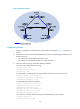
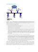
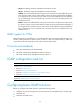
Configure the switches so that the receiver host receives multicast data from Source 2, which is outside the
OSPF domain.
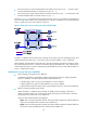
Figure 19 Network diagram
Configuration procedure
1. Assign an IP address and subnet mask for each interface according to Figure 19. (Details not
shown.)
2. Enable OSPF on Switch B and Switch C to make sure the following conditions are met: (Details not
shown.)
{ The switches are interoperable at the network layer.
{ The switches can dynamically update their routing information.
3. Enable IP multicast routing, and enable IGMP and PIM-DM:
# On Switch C, enable IP multicast routing.
<SwitchC> system-view
[SwitchC] multicast routing
[SwitchC-mrib] quit
# Enable IGMP on VLAN-interface 100 (the interface that connects to the receiver host).
[SwitchC] interface vlan-interface 100
[SwitchC-Vlan-interface100] igmp enable
[SwitchC-Vlan-interface100] quit
# Enable PIM-DM on VLAN-interface 101.
[SwitchC] interface vlan-interface 101
[SwitchC-Vlan-interface101] pim dm
[SwitchC-Vlan-interface101] quit
# On Switch A, enable IP multicast routing, and enable PIM-DM on each interface.
<SwitchA> system-view
[SwitchA] multicast routing
[SwitchA-mrib] quit
[SwitchA] interface vlan-interface 300
[SwitchA-Vlan-interface300] pim dm
[SwitchA-Vlan-interface300] quit