HP FlexFabric 11900 Switch Series Layer 2—LAN Switching Command Reference Part number: 5998-5273 Software version: Release 2111 and later Document version: 6W100-20140110
Legal and notice information © Copyright 2014 Hewlett-Packard Development Company, L.P. No part of this documentation may be reproduced or transmitted in any form or by any means without prior written consent of Hewlett-Packard Development Company, L.P. The information contained herein is subject to change without notice.
Contents Ethernet interface commands ······································································································································ 1 Common Ethernet interface commands ·························································································································· 1 bandwidth ································································································································································· 1 defa
interface loopback ················································································································································ 57 interface null··························································································································································· 57 reset counters interface loopback ························································································································ 58 reset counters
reset lacp statistics ··············································································································································· 107 shutdown ······························································································································································ 107 Port isolation commands ········································································································································· 109 dis
stp transmit-limit ··················································································································································· 157 vlan-mapping modulo ········································································································································· 157 Loop detection commands ······································································································································ 159 display loopbac
display lldp tlv-config ·········································································································································· 224 lldp admin-status ·················································································································································· 227 lldp check-change-interval ·································································································································· 228 lldp complianc
Ethernet interface commands Common Ethernet interface commands bandwidth Use bandwidth to configure the expected bandwidth of an interface. Use undo bandwidth to restore the default. Syntax bandwidth bandwidth-value undo bandwidth Default The expected bandwidth (in kbps) is the interface baud rate divided by 1000. Views Ethernet interface view Predefined user roles network-admin mdc-admin Parameters bandwidth-value: Specifies the expected bandwidth in the range of 1 to 400000000 kbps.
Syntax default Views Ethernet interface view Predefined user roles network-admin mdc-admin Usage guidelines CAUTION: The default command might interrupt ongoing network services. Make sure you are fully aware of the impacts of this command when you use it in a live network. This command might fail to restore the default settings for some commands for reasons such as command dependencies or system restrictions.
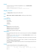
Examples # Change the description of interface Ten-GigabitEthernet 1/0/1 to lanswitch-interface. system-view [Sysname] interface ten-gigabitethernet 1/0/1 [Sysname-Ten-GigabitEthernet1/0/1] description lanswitch-interface display counters Use display counters to display interface traffic statistics.
XGE1/0/3 Overflow Overflow Overflow Overflow XGE1/0/4 0 0 0 0 Overflow: More than 14 digits (7 digits for column "Err"). --: Not supported. Table 1 Command output Field Description Interface Abbreviated interface name. Total (pkts) Total number of packets received or sent through the interface. Broadcast (pkts) Total number of broadcast packets received or sent through the interface. Multicast (pkts) Total number of multicast packets received or sent through the interface.
Usage guidelines The statistics cover only interfaces in up state. If an interface type is specified, the command displays traffic rate statistics for all up interfaces of the specified type over the last statistics polling interval. If no interface type is specified, the command displays traffic rate statistics for all up interfaces that have traffic counters over the last statistics polling interval.
In IRF mode: display ethernet statistics chassis chassis-number slot slot-number Views Any view Predefined user roles network-admin network-operator mdc-admin mdc-operator Parameters slot slot-number: Displays the Ethernet statistics on the specified card. The slot-number argument represents the number of the slot that houses the card. (In standalone mode.) chassis chassis-number slot slot-number: Displays the Ethernet statistics on the specified card of the specified IRF member device.
ETH receive packet statistics: Totalnum : 10447 ETHIINum : 4459 SNAPNum : 0 RAWNum : 0 LLCNum : 0 UnknownNum : 0 ForwardNum : 4459 ARP : 0 MPLS : 0 ISIS : 0 ISIS2 : 0 IP : 0 IPV6 : 0 ETH receive error statistics: NullPoint : 0 ErrIfindex : 0 ErrIfcb : 0 IfShut : 0 ErrAnalyse : 5988 ErrSrcMAC : 5988 ErrHdrLen : 0 ETH send packet statistics: L3OutNum : 211 VLANOutNum : 0 FastOutNum : 155 L2OutNum : 0 ETH send error statistics: MbufRelayNum : 0 NullMbuf : 0 E
Field Description Statistics about the error Ethernet packets in the outbound direction on the Ethernet interface module. Errors might be included in packets or occur during the receiving process. The items include: ETH receive error statistics • • • • NullPoint—Number of packets that include null pointers. ErrIfindex—Number of packets that include incorrect interface indexes. ErrIfcb—Number of packets that include incorrect interface control blocks.
Predefined user roles network-admin network-operator mdc-admin mdc-operator Parameters interface-type: Specifies an interface type. interface-number: Specifies an interface number. brief: Displays brief interface information. If you do not specify this keyword, the command displays detailed interface information. down: Displays information about interfaces in the down state and the causes. If you do not specify this keyword, this command displays information about interfaces in all states.
Last 300 seconds output: Input (total): 0 packets/sec 0 bytes/sec 0 packets, 0 bytes 0 unicasts, 0 broadcasts, Input (normal): 0 multicasts, 0 pauses 0 packets, - bytes 0 unicasts, 0 broadcasts, 0 multicasts, 0 pauses Input: 0 input errors, 0 runts, 0 giants, 0 throttles 0 CRC, 0 frame, - overruns, 0 aborts - ignored, - parity errors Output (total): 0 packets, 0 bytes 0 unicasts, 0 broadcasts, Output (normal): 0 multicasts, 0 pauses 0 packets, - bytes 0 unicasts, 0 broadcasts, 0 multicasts, 0
Field Description Bandwidth Expected bandwidth of the interface. Internet protocol processing: disabled Indicates that the interface cannot process IP packets. Last clearing of counters Time when the reset counters interface command was last used to clear the interface statistics. Never indicates the reset counters interface command has never been used on the interface since the device's startup. Last 300 seconds input Average input rate over the last 300 seconds in Bps, bps, and pps.
0 unicasts, 0 broadcasts, 0 multicasts, 0 pauses Output (normal): 0 packets, - bytes 0 unicasts, 0 broadcasts, 0 multicasts, 0 pauses Output: 0 output errors, - underruns, - buffer failures 0 aborts, 0 deferred, 0 collisions, 0 late collisions 0 lost carrier, - no carrier Table 5 Command output Field Description State of the Ethernet interface: • Administratively DOWN—The Ethernet interface was shut down with the shutdown command. The interface is administratively down.
Field Description Media type is Type of the interface media. Port hardware type is Type of the interface hardware. 10Mbps-speed mode The interface is operating at 10 Mbps. 100Mbps-speed mode The interface is operating at 100 Mbps. 1000Mbps-speed mode The interface is operating at 1000 Mbps. 10Gbps-speed mode The interface is operating at 10 Gbps. 40Gbps-speed mode The interface is operating at 40 Gbps.
Field Description Port priority Priority of the interface. Last clearing of counters: Never Time when the reset counters interface command was last used to clear statistics on the interface. Never indicates that the reset counters interface command was never used since the device was started. Peak value of input Peak rate of inbound traffic in Bps, and the time when the peak inbound traffic rate occurred.
Field Description overruns Number of packets dropped because the input rate of the port exceeded the queuing capability. Total number of illegal inbound packets: • Fragment frames—CRC error frames shorter than 64 bytes. The length can be an integral or non-integral value. • Jabber frames—CRC error frames greater than the maximum aborts frame length supported on the Ethernet interface (with an integral or non-integral length).
Field Description collisions Number of frames that the interface stopped transmitting because Ethernet collisions were detected during transmission. late collisions Number of frames that the interface deferred to transmit after transmitting their first 512 bits because of detected collisions. lost carrier Number of carrier losses during transmission. This counter increases by one when a carrier is lost, and applies to serial WAN interfaces.
Type: A - access; T - trunk; H - hybrid Interface Link Speed XGE1/0/3 UP Duplex Type PVID Description 10G(a) F(a) A 1 aaaaaaaaaaaaaaaaaaaaaaaaaaaaa aaaaaaaaaaaaaaaaaaaaaaaaaaaaaaaaaaaaaaaaa # Display information about interfaces in DOWN state and the causes.
Field Description Description Interface description configured by using the description command. If the description keyword is not specified in the display interface brief command, the Description field displays at most 27 characters. If the description keyword is specified in the display interface brief command, the field displays the full interface description. The brief information of interface(s) under bridge mode: Brief information about Layer 2 interfaces.
Field Description Cause for the physical link state of an interface to be DOWN: • Administratively—The port is manually shut down with the shutdown command. To restore the physical state of the interface, use the undo shutdown command. • DOWN ( Link-Aggregation interface down )—When an aggregate interface is shut down, the physical state of all member ports of the aggregate interface becomes DOWN, and the Cause field displays DOWN ( Link-Aggregation interface down ).
Parameters interface-type: Specifies an interface type. If you do not specify an interface type, this command displays information about dropped packets on all the interfaces on the device. interface-number: Specifies an interface number. If you specify an interface type only, this command displays information about dropped packets on the specified type of interfaces. summary: Displays the summary of dropped packets on all interfaces.
mdc-admin Parameters auto: Configures the interface to autonegotiate the duplex mode with the peer. full: Configures the interface to operate in full duplex mode, so that the interface can receive and transmit packets at the same time. half: Configures the interface to operate in half duplex mode, so that the interface can only receive or only transmit packets at one time. Usage guidelines Copper ports operating at 1000 Mbps or 10000 Mbps and fiber ports do not support the half keyword.
Examples # Enable TxRx mode generic flow control on the interface Ten-GigabitEthernet 1/0/1. system-view [Sysname] interface ten-gigabitethernet 1/0/1 [Sysname-Ten-GigabitEthernet1/0/1] flow-control flow-control receive enable Use flow-control receive enable to enable Rx mode generic flow control on an Ethernet port. Use undo flow-control to disable generic flow control on an Ethernet interface.
Use undo flow-interval to restore the default interval. Syntax flow-interval interval undo flow-interval Default The interface statistics polling interval is 300 seconds. Views Ethernet interface view Predefined user roles network-admin mdc-admin Parameters interval: Sets the statistics polling interval, in seconds. The interval is in the range of 5 to 300 and must be a multiple of 5. Examples # Set the statistics polling interval to 100 seconds on Ten-GigabitEthernet 1/0/1.
jumboframe enable Use jumboframe enable to allow jumbo frames within the specified length to pass through. Use undo jumboframe enable to prevent jumbo frames from passing through. Syntax jumboframe enable [ value ] undo jumboframe enable Default The device allows jumbo frames within 9216 bytes to pass through. Views Ethernet interface view Predefined user roles network-admin mdc-admin Parameters value: Sets the maximum length of Ethernet frames that are allowed to pass through.
mdc-admin Parameters delay-time: Sets the physical state change suppression interval (in seconds) on the Ethernet interface. The value range for this argument is 0 to 30. A value of 0 indicates that physical state changes are immediately reported to the CPU and are not suppressed. mode up: Suppresses the link-up events. mode updown: Suppresses both the link-up and link-down events.
Parameters external: Performs an external loopback test on the Ethernet interface. internal: Performs an internal loopback test on the Ethernet interface. Usage guidelines If an Ethernet interface does not work correctly, you can perform a loopback test on it to identify the problem. An Ethernet interface in a loopback test does not forward data traffic. On a physically down interface (displayed as in DOWN state), you can only perform an internal loopback test, and an external loopback test will fail.
After you change the link mode of an Ethernet interface, all the commands (except the shutdown command) on the Ethernet interface are restored to their defaults in the new link mode. Examples # Configure Ten-GigabitEthernet 1/0/1 to operate in bridge mode. system-view [Sysname] interface ten-gigabitethernet 1/0/1 [Sysname-Ten-GigabitEthernet1/0/1] port link-mode bridge port up-mode Use port up-mode to forcibly bring up a fiber port. Use undo port up-mode to restore the default.
Use priority-flow-control to enable PFC on an Ethernet interface through automatic negotiation or forcibly. Use undo priority-flow-control to disable PFC on the interface. Syntax priority-flow-control { auto | enable } undo priority-flow-control Default PFC is disabled on Ethernet interfaces. Views System view, Ethernet interface view Predefined user roles network-admin mdc-admin Parameters auto: Specifies the Ethernet interface to automatically negotiate with its peer to enable PFC.
Related commands priority-flow-control no-drop dot1p priority-flow-control no-drop dot1p IMPORTANT: This command is applicable to only SF cards. Use priority-flow-control no-drop dot1p to enable PFC for specific 802.1p priorities on an Ethernet interface. Use undo priority-flow-control no-drop dot1p to restore the default. Syntax priority-flow-control no-drop dot1p dot1p-list undo priority-flow-control no-drop dot1p Default PFC is disabled for all 802.1p priorities.
Table 9 The relationship between the PFC function and the generic flow control function flow-control Unconfigurable priority-flowcontrol enable Configured priority-flow-cont rol no-drop dot1p Remarks Configured You cannot enable flow control by using the flow-control command on a port where PFC is enabled and PFC is enabled for the specified 802.1p priority values. • On a port configured with the flow-control command, you can enable PFC, but you cannot enable PFC for specific 802.1p priorities.
Views User view Predefined user roles network-admin mdc-admin Parameters interface-type: Specifies an interface type. interface-number: Specifies an interface number. Usage guidelines Before collecting traffic statistics for a specific period of time on an interface, clear the old statistics first. If no interface type is specified, this command clears statistics for all interfaces. If only the interface type is specified, this command clears statistics for all interfaces of that type.
Parameters slot slot-number: Clears the Ethernet statistics on the specified card. The slot-number argument represents the number of the slot that houses the card. (In standalone mode.) chassis chassis-number slot slot-number: Clears the Ethernet statistics on the specified card of the specified IRF member device. The chassis-number argument represents the ID of the IRF member device. The slot-number argument represents the number of the slot that houses the card. (In IRF mode.
Syntax shutdown undo shutdown Default Ethernet interfaces are in up state. Views Ethernet interface view Predefined user roles network-admin mdc-admin Usage guidelines You might need to shut down and then bring up an Ethernet interface to make some interface configurations take effect. Examples # Shut down and then bring up Ten-GigabitEthernet 1/0/1.
10000: Sets the interface speed to 10000 Mbps. 40000: Sets the interface speed to 40000 Mbps. auto: Enables the interface to negotiate a speed with its peer. Usage guidelines For a copper Ethernet interface, use the speed command to set its speed to match the rate of its peer. For a fiber port, use the speed command to set its speed to match the rate of a transceiver module. Table 10 shows the support of interfaces for the keywords.
Usage guidelines If you need higher bandwidth, you can combine four 10-GE interfaces that are split from a 40-GE interface into a 40-GE interface. To make this command take effect on the four split 10-GE interfaces, execute this command on only one of the split 10-GE interfaces. After this command is successfully configured, the system prompts you to reboot the card that houses the four split 10-GE interfaces.
The 10-GE interfaces that are split from a 40-GE interface support the same configuration and attributes as common 10-GE interfaces, except that they are numbered differently. After this command is successfully configured, the system prompts you to reboot the card that houses the 40-GE interface. You must reboot the card and then the system deletes the 40-GE interface and creates the four 10-GE interfaces. Examples # Split 40-GE interface FortyGigE 1/0/1 into four 10-GE interfaces.
kbps max-kbps: Specifies the maximum number of kilobits of broadcast traffic that the Ethernet interface can forward per second. The value range for this argument (in kbps) is 0 to the maximum interface rate. Usage guidelines You can use the broadcast storm suppression function to limit the size of broadcast traffic on an interface. When the broadcast traffic on the interface exceeds this threshold, the system drops packets until the traffic drops below this threshold.
Parameters broadcast: Displays broadcast storm control settings and statistics. multicast: Displays multicast storm control settings and statistics. unicast: Displays unknown unicast storm control settings and statistics. interface interface-type interface-number: Specifies an interface by its type and number. Usage guidelines If you specify no argument or keyword, this command displays all storm control settings on all storm control-enabled interfaces.
Field Description Status of the storm control threshold event trap switch: Trap • on—The port sends threshold event traps. • off—The port does not send threshold event traps. Status of the storm control threshold event log switch: Log SwitchNum • on—The port sends threshold event log messages. • off—The port does not send threshold event log messages. Number of forwarding state changes of the interface. When the SwitchNum count reaches 65535, it resets automatically.
multicast-suppression Use multicast-suppression to enable multicast storm suppression and set the multicast storm suppression threshold. Use undo multicast-suppression to restore the default. Syntax multicast-suppression { ratio | pps max-pps | kbps max-kbps } undo multicast-suppression Default Ethernet interfaces do not suppress multicast traffic.
Examples # Set the multicast storm suppression threshold to 10000 kbps on Ten-GigabitEthernet 1/0/1. system-view [Sysname] interface ten-gigabitethernet 1/0/1 [Sysname-Ten-GigabitEthernet1/0/1] multicast-suppression kbps 10000 The actual value is 10048 on port Ten-GigabitEthernet1/0/1 currently. Related commands • broadcast-suppression • unicast-suppression storm-constrain Use storm-constrain to enable broadcast, multicast, or unknown unicast storm control on an Ethernet port.
particular type of traffic exceeds its upper threshold, the interface takes a certain action, which can be configured by using the storm-constrain control command. Either of the storm-constrain, broadcast-suppression, multicast-suppression, and unicast-suppression commands can suppress storm on a port. The storm-constrain command uses software to suppress traffic, and affects the device performance to a certain extent.
Views Layer 2 Ethernet interface view Predefined user roles network-admin mdc-admin Parameters block: Blocks this type of traffic, while forwarding other types of traffic. Even though the interface does not forward the blocked traffic, it still counts the traffic. When the blocked traffic is detected dropping below the lower threshold, the port begins to forward the traffic. shutdown: Shuts down automatically. The interface shuts down automatically and stops forwarding any traffic.
system-view [Sysname] interface ten-gigabitethernet 1/0/1 [Sysname-Ten-GigabitEthernet1/0/1] storm-constrain enable log storm-constrain enable trap Use storm-constrain enable trap to enable an Ethernet interface to send storm control threshold event traps. Use undo storm-constrain enable trap to disable trap sending.
Parameters seconds: Sets the traffic polling interval of the storm control module. The value range is 1 to 300 seconds. Usage guidelines The interval set by the storm-constrain interval command is specific to storm control. To set the statistics polling interval of an interface, use the flow-interval command. For network stability, use the default or a higher polling interval. Examples # Set the traffic statistics polling interval of the storm control module to 60 seconds.
Usage guidelines You can use the unicast storm suppression function to limit the size of unicast traffic on an interface. When the unicast traffic on the interface exceeds this threshold, the system discards packets until the unicast traffic drops below this threshold. Both the storm-constrain and unicast-suppression can suppress unicast storm on a port. The storm-constrain command uses software to suppress unicast traffic, and it affects the device performance to a certain extent.
The test result is for reference only. The cable length detection error is up to 5 m (about 16 ft). If a test item is not available, a hyphen (-) is displayed. Examples # Enable cable connection test on interface Ten-GigabitEthernet 1/0/1.
Loopback, null, and inloopback interface commands bandwidth Use bandwidth to configure the expected bandwidth of an interface. Use undo bandwidth to restore the default. Syntax bandwidth bandwidth-value undo bandwidth Default The expected bandwidth of a loopback interface is 0 kbps. Views Loopback interface view Predefined user roles network-admin mdc-admin Parameters bandwidth-value: Specifies the expected bandwidth in the range of 1 to 400000000 kbps.
Views Loopback interface view, null interface view Predefined user roles network-admin mdc-admin Usage guidelines CAUTION: The default command might interrupt ongoing network services. Make sure you are fully aware of the impacts of this command before using it on a live network. This command might fail to restore the default settings for some commands for reasons such as command dependencies and system restrictions.
You can use the display interface command to view the configured description. Examples # Set the description to for RouterID for interface loopback 1. system-view [Sysname] interface loopback 1 [Sysname-LoopBack1] description for RouterID display interface inloopback Use display interface inloopback to display information about the inloopback interface.
Last 300 seconds input rate: 0 bytes/sec, 0 bits/sec, 0 packets/sec Last 300 seconds output rate: 0 bytes/sec, 0 bits/sec, 0 packets/sec Input: 0 packets, 0 bytes, 0 drops Output: 0 packets, 0 bytes, 0 drops Table 13 Command output Field Description Current state Physical layer state of the interface, which is always UP, meaning that the inloopback interface can receive and transmit packets. Line protocol state Data link layer protocol state of the interface, which is always UP (spoofing).
Table 14 Command output Field Description Brief information on interface(s) under route mode: Brief information about the inloopback interface. Explains the Link field values: Link: ADM - administratively down; Stby - standby • ADM—The interface has been shut down by the network administrator. To recover its physical layer state, run the undo shutdown command. • Stby—The interface is a standby interface. Explains the Protocol field value. Protocol: (s) - spoofing (s) represents spoofing.
Parameters interface-number: Specifies a loopback interface by its number, which can be the number of any existing loopback interface. If you do not specify this argument, the command displays information about all existing loopback interfaces on the device. brief: Displays brief interface information. If you do not specify this keyword, the command displays detailed interface information. down: Displays information about interfaces in down state and the causes.
Field Description Maximum Transmit Unit MTU of the interface. Internet protocol processing: disabled Indicates that the interface cannot process Layer 3 packets (displayed when the interface is not configured with an IP address). Internet Address is 1.1.1.1/32 Primary Primary IP address of the interface (displayed when the interface is configured with a primary IP address). Physical: Loopback The physical type of the interface is loopback.
Interface Link Cause Loop1 ADM Administratively Table 16 Command output Field Description Brief information on interface(s) under route mode: Brief information about loopback interfaces. Explains the Link field values: • ADM—The interface has been shut down by the network Link: ADM - administratively down; Stby - standby administrator. To recover its physical layer state, run the undo shutdown command. • Stby—The interface is a standby interface.
Views Any view Predefined user roles network-admin network-operator mdc-admin mdc-operator Parameters 0: Specifies interface Null 0. brief: Displays brief interface information. If you do not specify this keyword, the command displays detailed interface information. description: Displays complete interface descriptions. If you do not specify this keyword, the command displays only the first 27 characters of interface descriptions.
Link: ADM - administratively down; Stby - standby Protocol: (s) - spoofing Interface Link Protocol Main IP Description NULL0 UP aaaaaaaaaaaaaaaaaaaaaaaaaaaaa UP(s) -- aaaaaaaaaaaaaaaaaaaaaaaaaaaaaaaaaaaaaaaaa For the command output, see Table 15 and Table 16. Related commands • interface null • reset counters interface null interface loopback Use interface loopback to create a loopback interface and enter loopback interface view. Use undo interface loopback to remove a loopback interface.
Syntax interface null 0 Default A device has only one null interface (Null 0), which cannot be created or deleted. Views System view Predefined user roles network-admin mdc-admin Parameters 0: Specifies interface Null 0. The null interface number is fixed at 0. Examples # Enter Null 0 interface view.
Related commands display interface loopback reset counters interface null Use reset counters interface null to clear the statistics on the null interface. Syntax reset counters interface [ null [ 0 ] ] Views User view Predefined user roles network-admin mdc-admin Parameters 0: Specifies the number of the null interface, which is fixed at 0.
Usage guidelines Use the shutdown command with caution, because the command disconnects the connection of the interface and disables the interface from communicating. Examples # Shut down interface loopback 1.
Bulk interface configuration commands display interface range Use display interface range to display information about interface ranges configured through the interface range name command. Syntax display interface range [ name name ] Views Any view Predefined user roles network-admin network-operator mdc-admin mdc-operator Parameters name name: Specifies an interface range by its name, a case-sensitive string of 1 to 32 characters.
Predefined user roles network-admin mdc-admin Parameters interface-list: Specifies an interface list in the format of interface-list = { interface-type interface-number [ to interface-type interface-number ] }&<1-5>. The interface-type interface-number argument specifies an interface by its type and number. &<1-5> indicates that you can specify up to five interfaces or interface lists.
Use interface range name name without the interface keyword to enter the view of an interface range with the specified name. Use undo interface range name to delete the interface range with the specified name. Syntax interface range name name [ interface interface-list ] undo interface range name name Views System view Predefined user roles network-admin mdc-admin Parameters name: Specifies an interface range name, a case-sensitive string of 1 to 32 characters.
• The maximum number of interface range names is only limited by the system resources. To guarantee bulk interface configuration performance, HP recommends configuring fewer than 1000 interface range names. Examples # Add Ten-GigabitEthernet 1/0/1 through Ten-GigabitEthernet 1/0/12 to interface range named myEthPort, and enter the interface range view.
MAC address table commands This document covers the configuration of unicast MAC address entries, including static, dynamic, blackhole, and multiport unicast MAC address entries. For more information about configuring static multicast MAC address entries, see IP Multicast Configuration Guide. For more information about MAC address table configuration in VPLS, see MPLS Configuration Guide. display mac-address Use display mac-address to display MAC address entries.
This command displays dynamic MAC address entries for an aggregate interface only when the aggregate interface has at least one Selected member port. Examples # Display MAC address entries for VLAN 100.
Syntax display mac-address aging-time Views Any view Predefined user roles network-admin network-operator mdc-admin mdc-operator Examples # Display the aging timer for dynamic MAC address entries. display mac-address aging-time MAC address aging time: 300s. Related commands mac-address timer display mac-address mac-learning Use display mac-address mac-learning to verify whether MAC address learning has been enabled globally or on an interface.
XGE1/0/2 Enabled XGE1/0/3 Enabled XGE1/0/4 Enabled Table 18 Command output Field Description Global MAC address learning status • Enabled. • Disabled. Learning Status • Enabled. • Disabled. Global MAC address learning status: MAC address learning status of an interface: Related commands mac-address mac-learning enable display mac-address statistics Use display mac-address statistics to display MAC address table statistics.
Static Multicast and Multiport MAC Address (User-defined) Count: 0 Total Multicast and Multiport MAC Addresses Available: 256 Table 19 Command output Field Description Dynamic Unicast Address (Learned) Count Number of dynamic unicast MAC address entries triggered by packets. Dynamic Unicast Address (Security-service-defined) Count Number of dynamic unicast MAC address entries triggered by the security service.
Predefined user roles network-admin mdc-admin Parameters dynamic: Specifies dynamic MAC address entries. static: Specifies static MAC address entries. multiport: Specifies multiport unicast MAC address entries. A frame whose destination MAC address matches a multiport unicast MAC address entry is sent out of multiple ports. mac-address: Specifies a MAC address in the format of H-H-H, excluding multicast and all-zero MAC addresses.
[Sysname] interface schannel-aggregation 1:2 [Sysname-Schannel-Aggregation1:2] mac-address static 000f-e201-0102 vlan 1 # Add a multiport unicast MAC address entry for MAC address 0001-0001-0101 on Ten-GigabitEthernet 1/0/1 and Ten-GigabitEthernet 1/0/2 that belong to VLAN 2.
static: Specifies static MAC address entries. blackhole: Specifies blackhole MAC address entries. The packets whose source or destination MAC addresses match blackhole MAC address entries are dropped. multiport: Specifies multiport unicast MAC address entries. A frame whose destination MAC address matches a multiport unicast MAC address entry is sent out of multiple ports. mac-address: Specifies a MAC address in the format of H-H-H, excluding multicast and all-zero MAC addresses.
Examples # Add a static entry for MAC address 000f-e201-0101. All frames that are destined for this MAC address are sent out of interface Ten-GigabitEthernet 1/0/1, which belongs to VLAN 2.
• Because disabling MAC address learning can result in broadcast storms, enable broadcast storm suppression after you disable MAC address learning on an interface. For more information about broadcast storm suppression, see Layer 2—LAN Switching Configuration Guide. • With MAC address learning enabled globally, you can disable MAC address learning for the specific interface or VLAN. This command does not take effect in a TRILL network, in a VPLS VSI, or for an S-channel in an EVB.
Default Low MAC address learning priority is used. Views Layer 2 Ethernet interface view, Layer 2 aggregate interface view Predefined user roles network-admin mdc-admin Parameters high: Assigns high MAC learning priority. low: Assigns low MAC learning priority. Usage guidelines The MAC address learning priority values can be high and low. An interface with high MAC address learning priority can learn any MAC address.
Predefined user roles network-admin mdc-admin Usage guidelines If ports on different cards of the same device or of different IRF member devices are selected ports from the same aggregation group, MAC address entries are synchronized among these cards regardless of whether MAC address synchronization is enabled. For more information about aggregation groups, see Layer 2—LAN Switching Configuration Guide. The MAC address table size might vary with different cards.
[Sysname] interface ten-gigabitethernet 1/0/1 [Sysname-Ten-GigabitEthernet1/0/1] mac-address max-mac-count 600 Related commands • mac-address • mac-address max-mac-count enable-forwarding mac-address max-mac-count enable-forwarding Use mac-address max-mac-count enable-forwarding to enable the device to forward frames with unknown source MAC addresses after the number of learned MAC addresses reaches the upper limit.
Syntax mac-address timer { aging seconds | no-aging } undo mac-address timer Default The aging timer for dynamic MAC address entries is 300 seconds. Views System view Predefined user roles network-admin mdc-admin Parameters aging seconds: Sets an aging timer for dynamic MAC address entries, in the range of 10 to 1000000 seconds. no-aging: Sets dynamic MAC address entries not to age. Usage guidelines After the network topology changes, the dynamic MAC address entries are not updated in a timely manner.
MAC Information commands mac-address information enable (interface view) Use mac-address information enable to enable MAC Information on an interface. Use undo mac-address information enable to disable MAC Information on an interface. Syntax mac-address information enable { added | deleted } undo mac-address information enable { added | deleted } Default MAC Information is disabled on an interface.
[Sysname-Schannel-Aggregation1:2] mac-address information enable added Related commands mac-address information enable (system view) mac-address information enable (system view) Use mac-address information enable to enable MAC Information globally. Use undo mac-address information enable to disable MAC Information globally. Syntax mac-address information enable undo mac-address information enable Default MAC Information is disabled globally.
Predefined user roles network-admin mdc-admin Parameters interval-time: Specifies the MAC change sending interval in the range of 1 to 20000 seconds. Usage guidelines To prevent syslog messages or SNMP notifications from being sent too frequently, set the MAC change sending interval to a larger value. Examples # Set the MAC change sending interval to 200 seconds.
Use undo mac-address information queue-length to restore the default. Syntax mac-address information queue-length value undo mac-address information queue-length Default The MAC Information queue length is 50. Views System view Predefined user roles network-admin mdc-admin Parameters value: Specifies the MAC Information queue length, which indicates the number of MAC change messages, in the range of 0 to 1000.
Ethernet link aggregation commands bandwidth Use bandwidth to configure the expected bandwidth for an interface. Use undo bandwidth to restore the default. Syntax bandwidth bandwidth-value undo bandwidth Default The expected bandwidth (in kbps) is the interface baud rate divided by 1000. Views Layer 2 aggregate interface view Predefined user roles network-admin mdc-admin Parameters bandwidth-value: Specifies the expected bandwidth in the range of 1 to 400000000 kbps.
Predefined user roles network-admin mdc-admin Usage guidelines CAUTION: The default command might interrupt ongoing network services. Make sure you are fully aware of the impacts of this command when you execute it on a live network. This command might fail to restore the default settings for some commands for reasons such as command dependencies and system restrictions.
display interface Use display interface to display aggregate interface information. Syntax display interface [ bridge-aggregation ] [ brief [ down | description ] ] display interface bridge-aggregation interface-number [ brief [ description ] ] Views Any view Predefined user roles network-admin network-operator mdc-admin mdc-operator Parameters bridge-aggregation: Displays information about Layer 2 aggregate interfaces. interface-number: Specifies an existing aggregate interface number.
Port link-type: access Tagged Vlan: none UnTagged Vlan: 1 Last clearing of counters: Last 300 seconds input: Last 300 seconds output: Input (total): Never 6900 packets/sec 885160 bytes/sec 0% 3150 packets/sec 404430 bytes/sec 0% 5364747 packets, 686688416 bytes 2682273 unicasts, 1341137 broadcasts, 1341337 multicasts, 0 pauses Input (normal): 5364747 packets, 686688416 bytes 2682273 unicasts, 1341137 broadcasts, 1341337 multicasts, 0 pauses Input: 0 input errors, 0 runts, 0 giants, 0 throttles 0
Field Description Port link-type Port link type: access, trunk, or hybrid. Packets from the specified VLANs are sent out of this interface with a VLAN tag: • Tagged Vlan: none—All packets are sent out of this interface without a VLAN tag. Tagged Vlan • Tagged Vlan: 1—Packets from VLAN 1 are sent out of this interface with a VLAN tag. This field is displayed when the port link type is access or hybrid.
Field Description If the speed of an interface is automatically negotiated, its speed attribute includes the auto negotiation flag, indicated by the letter a in parentheses. Speed or Duplex: (a)/A - auto; H - half; F - full If the duplex mode of an interface is automatically negotiated, its duplex mode attribute includes the auto negotiation flag, indicated by the letter a in parentheses or a capital A. The letter H indicates the half duplex mode, and the letter F indicates the full duplex mode.
Table 21 Command output Field Description Actor System ID: 0x8000, 0000-fc00-6504 Local system ID, which contains the system LACP priority (0x8000 in this sample output) and the system MAC address (0000-FC00-6504 in this sample output). Related commands lacp system-priority display link-aggregation load-sharing mode Use display link-aggregation load-sharing mode to display global or group-specific link-aggregation load sharing criteria.
# Display the link-aggregation load sharing criteria of the aggregation group that corresponds to Layer 2 aggregate interface Bridge-Aggregation 10. display link-aggregation load-sharing mode interface bridge-aggregation 10 Bridge-Aggregation10 Load-Sharing Mode: Layer 2 traffic: packet type-based sharing Layer 3 traffic: packet type-based sharing Table 22 Command output Field Description Global link-aggregation load sharing criteria.
Examples # Display detailed link aggregation information for Ten-GigabitEthernet 1/0/1, which is a member port of a static aggregation group.
Table 23 Command output Field Description LACP state flags. This field is one byte long, represented by ABCDEFGH from the least significant bit to the most significant bit. The letter is present when its bit is 1 and absent when its bit is 0. • A—Indicates whether LACP is enabled. 1 indicates enabled, and 0 indicates disabled. • B—Indicates the LACP short or long timeout. 1 indicates short timeout, and 0 indicates long timeout.
mdc-admin mdc-operator Usage guidelines Information about the remote system for a static link aggregation group is not displayed, because static link aggregation groups are unaware of information about the peer groups. Examples # Display the summary information for all aggregation groups.
Syntax display link-aggregation verbose [ bridge-aggregation [ interface-number ] ] Views Any view Predefined user roles network-admin network-operator mdc-admin mdc-operator Parameters bridge-aggregation: Displays detailed information about the Layer 2 aggregation groups that correspond to Layer 2 aggregate interfaces. interface-number: Specifies an existing aggregate interface by its number.
XGE1/0/2 2 32768 2 0x8000, 000f-e267-57ad {ACDEF} # Display detailed information about the aggregation group that corresponds to Layer 2 aggregate interface Bridge-Aggregation 20, which is a static aggregation group.
Field Description Mode of the aggregation group: Aggregation Mode • Static for static aggregation. • Dynamic for dynamic aggregation. System ID Local system ID, containing the system LACP priority and the system MAC address. Information about the local end: Local • • • • • Port—Port type and number. Status—Selected or Unselected state of the port. Priority—Port priority. Oper-Key—Operational key. Flag—LACP state flag.
Usage guidelines When you create a Layer 2 aggregate interface, the system automatically creates a Layer 2 aggregation group with the same number, which operates in static aggregation mode by default. If you remove the Layer 2 aggregate interface, you also remove the Layer 2 aggregation group, and any member ports leave the aggregation group. Examples # Create Layer 2 aggregate interface Bridge-Aggregation 1, and enter its view.
Default The system LACP priority is 32768. Views System view Predefined user roles network-admin mdc-admin Parameters system-priority: Specifies the system LACP priority in the range of 0 to 65535. The smaller the value, the higher the system LACP priority. Examples # Set the system LACP priority to 64.
source-ip: Performs load sharing in link aggregation groups based on source IP address. source-mac: Performs load sharing in link aggregation groups based on source MAC address. source-port: Performs load sharing in link aggregation groups based on source port. Usage guidelines The load sharing criteria that you configure overwrite the previous criteria. If unsupported load sharing criteria are configured, an error prompt appears.
Parameters vlan-id-list: Specifies a list of VLANs to be ignored in the format of vlan-id-list = { vlan-id1 [ to vlan-id2 ] }&<1-10>, where vlan-id1 and vlan-id2 are both in the range of 1 to 4094, vlan-id2 cannot be smaller than vlan-id1, and &<1-10> indicates that you can specify up to 10 vlan-id1 [ to vlan-id2 ] parameters.
Do not enable both spanning tree and link-aggregation traffic redirection at the same time, because light packet loss might occur when a card or the device reboots. Examples # Enable link-aggregation traffic redirection. system-view [Sysname] link-aggregation lacp traffic-redirect-notification enable link-aggregation load-sharing mode Use link-aggregation load-sharing mode to configure the link-aggregation load sharing criteria.
• Destination MAC address • Layer 1 MPLS label. • Destination IP address and source IP address • Destination MAC address and source MAC address • Layer 1 MPLS label and Layer 2 MPLS label Examples # Configure the destination MAC address as the load sharing criterion that is specific to the link aggregation group of aggregate interface Bridge-Aggregation 1.
link-aggregation mode Use link-aggregation mode dynamic to configure an aggregation group to operate in dynamic aggregation mode and enable LACP. Use undo link-aggregation mode to restore the default setting. Syntax link-aggregation mode dynamic undo link-aggregation mode Default An aggregation group operates in static aggregation mode.
Examples # Set the port priority of Layer 2 Ethernet interface Ten-GigabitEthernet 1/0/1 to 64. system-view [Sysname] interface ten-gigabitethernet 1/0/1 [Sysname-Ten-GigabitEthernet1/0/1] link-aggregation port-priority 64 Related commands lacp system-priority link-aggregation selected-port maximum Use link-aggregation selected-port maximum to configure the maximum number of Selected ports allowed in an aggregation group.
Examples # Configure the maximum number of Selected ports allowed as 5 in the aggregation group that corresponds to Layer 2 aggregate interface Bridge-Aggregation 1.
port link-aggregation group Use port link-aggregation group to assign the Ethernet interface to the specified aggregation group. Use undo port link-aggregation group to remove the Ethernet interface from the aggregation group to which it belongs. Syntax port link-aggregation group number undo port link-aggregation group Default An Ethernet interface does not belong to any aggregation group.
Usage guidelines Before collecting statistics for a Layer 2 aggregate interface within a specific period, clear its existing statistics. If no option is specified, the command clears the statistics for all interfaces in the system. If only the bridge-aggregation keyword is specified, the command clears the statistics for all Layer 2 aggregate interfaces. If the bridge-aggregation interface-number option is specified, the command clears the statistics for the specified Layer 2 aggregate interface.
Syntax shutdown undo shutdown Default Aggregate interfaces are up. Views Layer 2 aggregate interface view Predefined user roles network-admin mdc-admin Examples # Bring up Layer 2 aggregate interface Bridge-Aggregation 1.
Port isolation commands display port-isolate group Use display port-isolate group to display port isolation group information. Syntax display port-isolate group [ group-number ] Views Any view Predefined user roles network-admin network-operator mdc-admin mdc-operator Parameters group-number: Specifies an isolation group by its number in the range of 1 to 8. Examples # Display all isolation groups.
Related commands port-isolate enable port-isolate enable Use port-isolate enable to assign a port to an isolation group. Use undo port-isolate enable to remove a port from an isolation group. Syntax port-isolate enable group group-number undo port-isolate enable Default No ports are assigned to an isolation group.
port-isolate group Use port-isolate group to create an isolation group. Use undo port-isolate group to delete isolation groups. Syntax port-isolate group group-number undo port-isolate group { group-number | all } Default No isolation group exists. Views System view Predefined user roles network-admin mdc-admin Parameters group-number: Specifies an isolation group by its number in the range of 1 to 8. all: Deletes all isolation groups.
Spanning tree commands active region-configuration Use active region-configuration to activate your MST region configuration. Syntax active region-configuration Views MST region view Predefined user roles network-admin mdc-admin Usage guidelines When you configure MST region parameters, MSTP launches a new spanning tree calculation process that might cause network topology instability. This is most likely to occur when you configure the VLAN-to-instance mapping table.
Syntax check region-configuration Views MST region view Predefined user roles network-admin mdc-admin Usage guidelines Two or more spanning tree devices belong to the same MST region only if they are configured with the same format selector (0 by default and not configurable), MST region name, and MST region revision level, have the same VLAN-to-instance mapping entries in the MST region, and are connected through a physical link.
display stp Use display stp to display spanning tree status and statistics information. Based on the information, you can analyze and maintain the network topology or determine whether the spanning tree is working correctly.
If you specify a port list, this command displays the spanning tree information for the specified ports. The displayed information is sorted by port name. • In MSTP mode: • If you do not specify any MSTI or port, this command displays the spanning tree information of all MSTIs on all ports. The displayed information is sorted by MSTI ID and by port name in each MSTI. • If you specify an MSTI but not a port, this command displays the spanning tree information on all ports in that MSTI.
Field Description Protection type on the port: • • • • Protection ROOT—Root guard. LOOP—Loop guard. BPDU—BPDU guard. NONE—No protection. # In MSTP mode, display the detailed spanning tree status and statistics of all MSTIs on all ports. display stp -------[CIST Global Info][Mode MSTP]------Bridge ID : 32768.000f-e200-2200 Bridge times : Hello 2s MaxAge 20s FwdDelay 15s MaxHops 20 Root ID/ERPC : 0.00e0-fc0e-6554, 200200 RegRoot ID/IRPC : 32768.000f-e200-2200, 0 RootPort ID : 128.
Root type : Primary root Master bridge : 32768.000f-e23e-9ca4 Cost to master : 0 TC received : 0 # Display the spanning tree status and statistics when the spanning tree feature is disabled. display stp Protocol status : Disabled Protocol Std. : IEEE 802.1s Version : 3 CIST Bridge-Prio.
Field Description Port role: Port role (Boundary) Port cost(Legacy) Desg.bridge/port • • • • • • Alternate. Backup. Root. Designated. Master. Disabled. The port is a regional boundary port. Path cost of the port. The field in parentheses indicates the standard (legacy, dot1d-1998, or dot1t) used for port path cost calculation. • Config—Configured value. • Active—Actual value. Designated bridge ID and port ID of the port.
Field Description Major parameters for the port: Port times • • • • • Hello—Hello timer. MaxAge—Maximum age timer. FwdDelay—Forward delay timer. MsgAge—Message age timer. RemHops—Remaining hops. BPDU sent Statistics on sent BPDUs. BPDU received Statistics on received BPDUs. RegRoot ID/IRPC MSTI regional root/internal path cost. MSTI root type: Root Type • Primary root. • Secondary root. Master bridge MSTI root bridge ID. Cost to master Path cost from the MSTI to the master bridge.
mdc-admin mdc-operator Examples # In MSTP mode, display information about ports that are blocked by spanning tree protection functions. display stp abnormal-port MSTID Blocked Port Reason 1 Ten-GigabitEthernet1/0/1 Root-Protected 2 Ten-GigabitEthernet1/0/2 Loop-Protected 12 Ten-GigabitEthernet1/0/3 Loopback-Protected Table 30 Command output Field Description MSTID MSTI of the blocked port. Blocked Port Name of a blocked port.
Usage guidelines In MSTP mode: • If you do not specify any MSTI or port, this command displays the BPDU statistics of all MSTIs on all ports. The displayed information is sorted by port name and by MSTI ID on each port. • If you specify a port but not an MSTI, this command displays the BPDU statistics of all MSTIs on the port. The displayed information is sorted by MSTI ID. • If you specify both an MSTI ID and a port, this command displays the BPDU statistics of the specified MSTI on the port.
Table 31 Command output Field Description Port Port name. Instance-Independent Statistics not related to any particular MSTI. Type Statistical item. Looped-back BPDUs BPDUs sent and then received by the same port. MAX-aged BPDUs BPDUs whose max age was exceeded. TCN sent TCN BPDUs sent. TCN received TCN BPDUs received. TCA sent TCA BPDUs sent. TCA received TCA BPDUs received. Config sent Configuration BPDUs sent. Config received Configuration BPDUs sent.
Examples # Display information about ports that were shut down by spanning tree protection functions. display stp down-port Down Port Reason Ten-GigabitEthernet1/0/1 BPDU-Protected Table 32 Command output Field Description Down Port Name of a port that was shut down by the spanning tree protection functions. Reason Reason that the port was shut down. BPDU-Protected indicates the BPDU guard function.
Usage guidelines In STP or RSTP mode, the displayed information is sorted by port role calculation time. In MSTP mode: • If you do not specify any MSTI, this command displays the historical port role calculation information for all MSTIs. The displayed information is sorted by MSTI ID and by port role calculation time in each MSTI. • If you specify an MSTI, this command displays the historical port role calculation information for the specified MSTI by the sequence of port role calculation time.
display stp region-configuration Use display stp region-configuration to display effective MST region configuration information, including the region name, revision level, and user-configured VLAN-to-instance mappings. Syntax display stp region-configuration Views Any view Predefined user roles network-admin network-operator mdc-admin mdc-operator Examples # In MSTP mode, display effective MST region configuration information.
display stp root Use display stp root to display the root bridge information of spanning trees. Syntax display stp root Views Any view Predefined user roles network-admin network-operator mdc-admin mdc-operator Examples # In MSTP mode, display the root bridge information of all spanning trees. display stp root MSTID Root Bridge ID ExtPathCost IntPathCost Root Port 0 0.
mdc-admin mdc-operator Parameters instance instance-list: Displays the statistics of TC/TCN BPDUs received and sent by all ports in the MSTIs that are specified by an instance list, in the format of instance-list = { instance-id [ to instance-id ] }&<1-10>, where &<1-10> indicates that you can specify up to 10 instances or instance ranges. The value range for the instance-id argument is 0 to 4094, and the value 0 represents the CIST.
Table 36 Command output Field Description Port Port name. Receive Number of TC/TCN BPDUs received on each port. Send Number of TC/TCN BPDUs sent by each port. instance Use instance to map a list of VLANs to an MSTI. Use undo instance to remap the specified VLAN or all VLANs to the CIST (MSTI 0). Syntax instance instance-id vlan vlan-id-list undo instance instance-id [ vlan vlan-id-list ] Default All VLANs are mapped to the CIST.
Examples # Map VLAN 2 to MSTI 1. system-view [Sysname] stp region-configuration [Sysname-mst-region] instance 1 vlan 2 Related commands • active region-configuration • check region-configuration • display stp region-configuration region-name Use region-name to configure the MST region name. Use undo region-name to restore the default MST region name. Syntax region-name name undo region-name Default The MST region name of a device is its MAC address.
• instance • revision-level • vlan-mapping modulo reset stp Use reset stp to clear spanning tree statistics. The spanning tree statistics include the numbers of TCN BPDUs, configuration BPDUs, RST BPDUs, and MST BPDUs that are sent and received through the specified ports.
Predefined user roles network-admin mdc-admin Parameters level: Specifies an MSTP revision level in the range of 0 to 65535. Usage guidelines The MSTP revision level, the MST region name, and the VLAN-to-instance mapping table of a device determine the device's MST region. When the MST region name and VLAN-to-instance mapping table are both the same for two MST regions, they can still be differentiated by their MSTP revision levels.
Examples # Enable the BPDU guard function. system-view [Sysname] stp bpdu-protection stp bridge-diameter Use stp bridge-diameter to specify the network diameter, which is the maximum possible number of stations between any two terminal devices on the switched network. Use undo stp bridge-diameter to restore the default. Syntax stp bridge-diameter diameter undo stp bridge-diameter Default The network diameter of the switched network is 7.
Use undo stp compliance to restore the default. Syntax stp compliance { auto | dot1s | legacy } undo stp compliance Default A port automatically recognizes the formats of received MSTP packets and determines the formats of MSTP packets to be sent based on the recognized formats.
Views Layer 2 Ethernet interface view, Layer 2 aggregate interface view Predefined user roles network-admin mdc-admin Usage guidelines Enable this feature both globally and on ports connected to other vendors' devices. To minimize impact, enable the feature on all associated ports before you enable it globally. When the setting is configured in Layer 2 Ethernet interface view, it takes effect on only that interface.
Parameters instance instance-list: Sets the path cost of the port in the MSTIs that are specified by an instance list, in the format of instance-list = { instance-id [ to instance-id ] }&<1-10>, where &<1-10> indicates that you can specify up to 10 instances or instance ranges. The value range for the instance-id argument is 0 to 4094, and the value 0 represents the CIST. cost: Specifies the path cost of the port, with an effective range that depends on the path cost calculation standard that is adopted.
Views Layer 2 Ethernet interface view, Layer 2 aggregate interface view Predefined user roles network-admin mdc-admin Usage guidelines If a port directly connects to a user terminal rather than to another device or a shared LAN segment, this port is regarded as an edge port. In case the network topology changes, an edge port does not cause a temporary loop. You can enable the port to transit to the forwarding state rapidly by configuring it as an edge port.
Views Layer 2 Ethernet interface view, Layer 2 aggregate interface view Predefined user roles network-admin mdc-admin Usage guidelines When you enable the spanning tree feature, the device operates in STP, RSTP, or MSTP mode, depending on the spanning tree mode setting. When you enable the spanning tree feature, the device dynamically maintains the spanning tree status of VLANs, based on received configuration BPDUs.
Usage guidelines Enable this feature both globally and on ports connected to other vendors' devices. To minimize impact, enable the feature on all associated ports before you enable it globally. Examples # Enable digest snooping on Ten-GigabitEthernet 1/0/1 and then globally.
• stp mode stp global mcheck Use stp global mcheck to perform the mCheck operation globally. Syntax stp global mcheck Views System view Predefined user roles network-admin mdc-admin Usage guidelines If a port on a device running MSTP or RSTP connects to an STP device, this port automatically transits to the STP mode when the port receives STP BPDUs.
Predefined user roles network-admin mdc-admin Usage guidelines On a port, the loop guard function is mutually exclusive with the root guard function or the edge port setting. When the setting is configured in Layer 2 Ethernet interface view, it takes effect on only that interface. When the setting is configured in Layer 2 aggregate interface view, it takes effect on only the aggregate interface.
[Sysname] stp max-hops 35 Related commands display stp stp mcheck Use stp mcheck to perform the mCheck operation on a port. Syntax stp mcheck Views Layer 2 Ethernet interface view, Layer 2 aggregate interface view Predefined user roles network-admin mdc-admin Usage guidelines If a port on a device that is running MSTP or RSTP connects to an STP device, the port automatically transits to the STP mode when the port receives STP BPDUs.
stp mode Use stp mode to configure the spanning tree operating mode. Use undo stp mode to restore the default. Syntax stp mode { mstp | rstp | stp } undo stp mode Default A spanning tree device operates in MSTP mode. Views System view Predefined user roles network-admin mdc-admin Parameters mstp: Configures the spanning tree device to operate in MSTP mode. rstp: Configures the spanning tree device to operate in RSTP mode. stp: Configures the spanning tree device to operate in STP mode.
Default No Agreement Check is disabled. Views Layer 2 Ethernet interface view, Layer 2 aggregate interface view Predefined user roles network-admin mdc-admin Usage guidelines This command takes effect only after you enable it on the root port. When the setting is configured in Layer 2 Ethernet interface view, it takes effect on only that interface. When the setting is configured in Layer 2 aggregate interface view, it takes effect on only the aggregate interface.
legacy: Configures the device to calculate the default path cost for ports based on a private standard. Usage guidelines If you change the standard that the device uses in calculating the default path costs, you restore the path costs to the default. Examples # Configure the device to calculate the default path cost for ports based on IEEE 802.1d-1998.
If the physical link to which the port connects is not a point-to-point link but you set it to be one, the configuration might cause a temporary loop. When the setting is configured in Layer 2 Ethernet interface view, it takes effect on only that interface. When the setting is configured in Layer 2 aggregate interface view, it takes effect on only the aggregate interface.
When the setting is configured in Layer 2 aggregate interface view, it takes effect on only the aggregate interface. When the setting is configured on a member port in an aggregation group, it takes effect only after the port leaves the aggregation group. Examples # In MSTP mode, set the priority of port Ten-GigabitEthernet 1/0/3 to 16 in MSTI 2.
The output shows that Ten-GigabitEthernet 1/0/1 in MSTI 2 transited to the discarding state and Ten-GigabitEthernet 1/0/2 in MSTI 2 transited to the forwarding state. stp priority Use stp priority to set the priority of the device. Use undo stp priority to restore the default priority. Syntax stp [ instance instance-list ] priority priority undo stp [ instance instance-list ] priority Default The device priority is 32768.
• All VLANs are mapped to the CIST. • The MSTP revision level is 0. Views System view Predefined user roles network-admin mdc-admin Usage guidelines After you enter MST region view, you can configure MST region parameters, including the region name, VLAN-to-instance mappings, and revision level. Examples # Enter MST region view. system-view [Sysname] stp region-configuration [Sysname-mst-region] stp role-restriction Use stp role-restriction to enable port role restriction.
system-view [Sysname] interface ten-gigabitethernet 1/0/1 [Sysname-Ten-GigabitEthernet1/0/1] stp role-restriction stp root primary Use stp root primary to configure the device as the root bridge. Use undo stp root to restore the default. Syntax stp [ instance instance-list ] root primary undo stp [ instance instance-list ] root Default A device is not a root bridge.
Syntax stp [ instance instance-list ] root secondary undo stp [ instance instance-list ] root Default A device is not a secondary root bridge. Views System view Predefined user roles network-admin mdc-admin Parameters instance instance-list: Configures the device as a secondary root bridge in the MSTIs that are specified by an instance list, in the format of instance-list = { instance-id [ to instance-id ] }&<1-10>, where &<1-10> indicates that you can specify up to 10 instances or instance ranges.
Predefined user roles network-admin mdc-admin Usage guidelines On a port, the loop guard function and the root guard function are mutually exclusive. When the setting is configured in Layer 2 Ethernet interface view, it takes effect on only that interface. When the setting is configured in Layer 2 aggregate interface view, it takes effect on only the aggregate interface.
Examples # Disable the TC-BPDU attack guard function for the device. system-view [Sysname] undo stp tc-protection Related commands stp tc-protection threshold stp tc-protection threshold Use stp tc-protection threshold to configure the maximum number of forwarding address entry flushes that the device can perform within a certain interval (every 10 seconds). Use undo stp tc-protection threshold to restore the default.
Default TC-BPDU transmission restriction is disabled. Views Layer 2 Ethernet interface view, Layer 2 aggregate interface view Predefined user roles network-admin mdc-admin Usage guidelines When TC-BPDU transmission restriction is enabled on a port, the port does not send TC-BPDUs to other ports, and it does not delete MAC address entries. When the setting is configured in Layer 2 Ethernet interface view, it takes effect on only that interface.
Usage guidelines The forward delay timer determines the time interval of state transition. To prevent temporary loops, a spanning tree port goes through the learning (intermediate) state before it transits from the discarding state to the forwarding state. To stay synchronized with the remote device, the port has a wait period between transition states that is determined by the forward delay timer. HP recommends not setting the forward delay with this command.
protocols automatically calculate the optimal settings for the hello timer. If the network diameter uses the default value, the hello timer also uses the default value. Examples # In MSTP mode, set the hello time to 400 centiseconds. system-view [Sysname] stp timer hello 400 Related commands • stp bridge-diameter • stp timer forward-delay • stp timer max-age stp timer max-age Use stp timer max-age to set the max age timer. Use undo stp timer max-age to restore the default.
Related commands • stp bridge-diameter • stp timer forward-delay • stp timer hello stp timer-factor Use stp timer-factor to configure the timeout interval by setting the timeout factor. Timeout interval = timeout factor × 3 × hello time. Use undo stp timer-factor to restore the default. Syntax stp timer-factor factor undo stp timer-factor Default The timeout factor of a device is set to 3.
stp transmit-limit Use stp transmit-limit to set the BPDU transmission rate of a port. Use undo stp transmit-limit to restore the default. Syntax stp transmit-limit limit undo stp transmit-limit Default The BPDU transmission rate of all ports is 10. Each port can send 10 BPDUs within each hello time. Views Layer 2 Ethernet interface view, Layer 2 aggregate interface view Predefined user roles network-admin mdc-admin Parameters limit: Sets the BPDU transmission rate in the range of 1 to 255.
Default All VLANs are mapped to the CIST (MSTI 0). Views MST region view Predefined user roles network-admin mdc-admin Parameters modulo: Sets the modulo value in the range of 1 to 64. Usage guidelines You cannot map a VLAN to different MSTIs. If you map a VLAN that has been mapped to an MSTI to a new MSTI, the old mapping is automatically removed. This command maps each VLAN to the MSTI whose ID is (VLAN ID – 1) % modulo + 1, where (VLAN ID – 1) % modulo is the modulo operation for (VLAN ID – 1).
Loop detection commands display loopback-detection Use display loopback-detection to display the loop detection configuration and status. Syntax display loopback-detection Views Any view Predefined user roles network-admin network-operator mdc-admin mdc-operator Example # Display the loop detection configuration and status. display loopback-detection Loopback detection is enabled. Loopback detection interval is 30 second(s).
loopback-detection action Use loopback-detection action to configure the loop protection action on a port. Use undo loopback-detection action to restore the default. Syntax In Layer 2 Ethernet interface view: loopback-detection action { block | no-learning | shutdown } undo loopback-detection action In Layer 2 aggregate interface view: loopback-detection action shutdown undo loopback-detection action Default When the device detects a loop on a port, it generates a log but performs no action on the port.
loopback-detection enable Use loopback-detection enable to enable loop detection on a port. Use undo loopback-detection enable to disable loop detection on a port. Syntax loopback-detection enable vlan { vlan-list | all } undo loopback-detection enable vlan { vlan-list | all } Default The loop detection function is disabled on ports.
Syntax loopback-detection global action shutdown undo loopback-detection global action Default When the device detects a loop on a port, it generates a log but performs no action on the port. Views System view Predefined user roles network-admin mdc-admin Parameters shutdown: Enables the shutdown mode. If a loop is detected, the device generates a log and shuts down the port. Usage guidelines Use this command to configure the loop protection action globally.
Predefined user roles network-admin mdc-admin Parameters vlan-list: Specifies a VLAN list, in the format of { vlan-id [ to vlan-id ] }&<1-10>, where vlan-id represents the VLAN ID in the range of 1 to 4094, and &<1-10> indicates that you can specify up to 10 vlan-id [ to vlan-id ] parameters. all: Specifies all existing VLANs. Usage guidelines Use this command to enable loop detection globally. To enable loop detection on specific ports, use the loopback-detection enable command in interface view.
Usage guidelines With loop detection enabled, the device sends loop detection frames at the specified interval. A shorter interval offers more sensitive detection but consumes more resources. Consider the system performance and loop detection speed when you set the loop detection interval. Example # Set the loop detection interval to 10 seconds.
VLAN commands Basic VLAN commands bandwidth Use bandwidth to configure the expected bandwidth of an interface. Use undo bandwidth to restore the default. Syntax bandwidth bandwidth-value undo bandwidth Default The expected bandwidth (in kbps) is the interface baud rate divided by 1000. Views VLAN interface view Predefined user roles network-admin mdc-admin Parameters bandwidth-value: Specifies the expected bandwidth in the range of 1 to 400000000 kbps.
Predefined user roles network-admin mdc-admin Usage guidelines CAUTION: The default command might interrupt ongoing network services. Make sure you are fully aware of the impacts of this command when you use it in a live network. This command might fail to restore the default settings for some commands for reasons such as command dependencies or system restrictions.
bracket (>), hyphen (-), underscore(_), plus sign (+), equal sign (=), vertical bar (|), back slash (\), colon (:), semi-colon (;) quotation marks ("), apostrophe ('), comma (,), dot (.), and slash (/), spaces, and other Unicode characters and symbols. For a VLAN or VLAN interface, this argument is a string of 1 to 255 characters.
description: Displays the full description of the specified interface. If the keyword is not specified, the command displays at most the first 27 characters of the interface description. If the keyword is specified, the command displays all characters of the interface description. Examples # Display information for VLAN interface 10.
Field Description Internet protocol processing : disabled The interface is not capable of processing IP packets. This information is displayed when the interface is not configured with an IP address. Internet Address is 192.168.1.54/24 Primary The primary IP address of the interface is 192.168.1.54/24. This information is displayed only if the primary IP address is configured for the interface. P Packet Frame Type IPv4 outgoing frame format.
mdc-admin mdc-operator Parameters vlan-id1: Displays information about a VLAN specified by its VLAN ID. The value range for this argument is 1 to 4094. vlan-id1 to vlan-id2: Displays information about VLANs that are specified by a VLAN ID range. The vlan-id1 and vlan-id2 arguments specify VLAN IDs. The value range for each of the two arguments is 1 to 4094. The vlan-id1 argument cannot be greater than the vlan-id2 argument. all: Displays all VLAN information except for the reserved VLANs.
Field Description Description Description of the VLAN. Name Name configured for the VLAN. IP address Primary IP address of the VLAN interface (available only when an IP address is configured for the VLAN interface). To display secondary IP addresses, use the display interface vlan-interface command in any view or the display this command in VLAN interface view. Subnet mask Subnet mask of the primary IP address (available only when an IP address is configured for the VLAN interface).
[Sysname-Vlan-interface2] Related commands display interface vlan-interface name Use name to configure a name for the VLAN. Use undo name to restore the default name of the VLAN. Syntax name text undo name Default The name of a VLAN is VLAN vlan-id, which specifies the ID of the VLAN. For example, the name of VLAN 100 is VLAN 0100. Views VLAN view Predefined user roles network-admin mdc-admin Parameters text: Specifies a VLAN name, a string of 1 to 32 characters.
Syntax In standalone mode: service slot slot-number undo service slot In IRF mode: service chassis chassis-number slot slot-number undo service chassis Default No LPU is specified for forwarding the traffic on the VLAN interface. Views VLAN interface view Predefined user roles network-admin mdc-admin Parameters slot slot-number: Specifies an LPU. The slot-number argument represents the number of the slot that holds the LPU. (In standalone mode.
shutdown Use shutdown to shut down a VLAN interface. Use undo shutdown to cancel the action of manually shutting down a VLAN interface. Syntax shutdown undo shutdown Default A VLAN interface is not manually shut down. The VLAN interface is up if one or more ports in the VLAN is up, and it goes down if all ports in the VLAN go down.
Syntax vlan { vlan-id1 [ to vlan-id2 ] | all } undo vlan { vlan-id1 [ to vlan-id2 ] | all } Default VLAN 1 (the default VLAN) exists. Views System view Predefined user roles network-admin mdc-admin Parameters vlan-id1, vlan-id2: Specifies a VLAN ID. The value range is 1 to 4094. vlan-id1 to vlan-id2: Specifies a VLAN range. The vlan-id1 and vlan-id2 arguments specify VLAN IDs. The value range for each of the two arguments is 1 to 4094. The vlan-id1 argument cannot be greater than vlan-id2.
Syntax display port { hybrid | trunk } Views Any view Predefined user roles network-admin network-operator mdc-admin mdc-operator Parameters hybrid: Displays hybrid ports. trunk: Displays trunk ports. Examples # Display information about the hybrid ports in the system.
undo port interface-list Default All ports are in VLAN 1.
mdc-admin Parameters vlan-id: Specifies a VLAN ID in the range of 1 to 4094. Make sure the VLAN specified by the VLAN ID already exists. Usage guidelines Before assigning an access port to a VLAN, make sure the VLAN has been created. • The configuration made in Layer 2 Ethernet interface view applies only to the port. • The configuration made in Layer 2 aggregate interface view applies to the aggregate interface and its aggregation member ports.
Usage guidelines You can use a nonexistent VLAN as the PVID for a hybrid port. If you remove the PVID of a hybrid port with the undo vlan command, the setting of the PVID on the port is not affected. HP recommends that you set the same PVID for the local and remote hybrid ports. You must configure the hybrid port to allow and forward packets from the PVID by using the port hybrid vlan command. • The configuration made in Layer 2 Ethernet interface view applies only to the port.
Predefined user roles network-admin mdc-admin Parameters vlan-id-list: Specifies a list of existing VLANs in the format of vlan-id-list = { vlan-id1 [ to vlan-id2 ] }&<1-10>, where the value range for vlan-id1 and vlan-id2 is 1 to 4094, vlan-id2 cannot be smaller than vlan-id1, and &<1-10> indicates that you can specify up to 10 vlan-id1 [ to vlan-id2 ] parameters. tagged: Configures the ports to send the packets of the specified VLANs without removing VLAN tags.
Views Layer 2 Ethernet interface view, Layer 2 aggregate interface view, S-channel interface view, S-channel aggregate interface view Predefined user roles network-admin mdc-admin Parameters access: Configures the link type of a port as access. hybrid: Configures the link type of a port as hybrid. trunk: Configures the link type of a port as trunk. Usage guidelines To change the link type of a port from trunk to hybrid or vice versa, first set the link type to access.
Predefined user roles network-admin mdc-admin Parameters vlan-id-list: Specifies a list of VLANs in the format of vlan-id-list = { vlan-id1 [ to vlan-id2 ] }&<1-10>, where the value range for vlan-id1 and vlan-id2 is 1 to 4094, vlan-id2 cannot be smaller than vlan-id1, and &<1-10> indicates that you can specify up to 10 vlan-id1 [ to vlan-id2 ] parameters. all: Permits all VLANs to pass through the trunk ports.
Views Layer 2 Ethernet interface view, Layer 2 aggregate interface view, S-channel interface view, S-channel aggregate interface view Predefined user roles network-admin mdc-admin Parameters vlan-id: Specifies a VLAN ID in the range of 1 to 4094. Usage guidelines You can use a nonexistent VLAN as the PVID for a trunk port. If you remove the PVID of a trunk port with the undo vlan command, the setting of the PVID on the port is not affected.
Private VLAN commands display private-vlan Use display private-vlan to display the associations between a primary VLAN and secondary VLANs and information about the primary VLAN and secondary VLANs. Syntax display private-vlan [ primary-vlan-id ] Views Any view Predefined user roles network-admin network-operator mdc-admin mdc-operator Parameters primary-vlan-id: Specifies a primary VLAN ID in the range of 1 to 4094.
VLAN ID: 3 VLAN type: Static Private VLAN type: Secondary Route interface: Configured Description: VLAN 0003 Name: VLAN 0003 Tagged ports: None Untagged ports: Ten-GigabitEthernet1/0/2 Ten-GigabitEthernet1/0/3 VLAN ID: 4 VLAN type: Static Private VLAN type: Secondary Route interface: Not configured Description: VLAN 0004 Name: VLAN 0004 Tagged ports: None Untagged ports: Ten-GigabitEthernet1/0/2 Ten-GigabitEthernet1/0/4 Table 41 Output description Field Description VLAN type VLAN type: Dynamic or
Field Description Name VLAN name. Tagged ports Ports through which packets from the VLAN are sent with tags. Untagged ports Ports through which packets from the VLAN are sent without tags. Related commands • private-vlan • private-vlan primary port private-vlan host Use port private-vlan host to configure the port to operate in host mode. If the port has been assigned to a secondary VLAN, the command also assigns the port to the primary VLAN that is associated with the secondary VLAN.
[Sysname] interface ten-gigabitethernet 1/0/1 [Sysname-Ten-GigabitEthernet1/0/1] port private-vlan host [Sysname-Ten-GigabitEthernet1/0/1] display this # interface Ten-GigabitEthernet1/0/1 port link-mode bridge port private-vlan host # return [Sysname-Ten-GigabitEthernet1/0/1] port access vlan 20 [Sysname-Ten-GigabitEthernet1/0/1] display this # interface Ten-GigabitEthernet1/0/1 port link-mode bridge port private-vlan host port link-type hybrid undo port hybrid vlan 1 port hybrid vlan 2 20 untagged port hy
mdc-admin Parameters vlan-id: Specifies a VLAN ID in the range of 1 to 4094. Though VLAN 1 is in the valid value range, it cannot be configured in the command. Usage guidelines If the port is an access port, the device changes the link type of the port to hybrid and configures the specified VLAN as the PVID of the port. If the port is a trunk or hybrid port, the device does not change the link type or PVID of the port.
[Sysname-Ten-GigabitEthernet1/0/1] undo port private-vlan [Sysname-Ten-GigabitEthernet1/0/1] display this # interface Ten-GigabitEthernet1/0/1 port link-mode bridge port link-type hybrid undo port hybrid vlan 1 port hybrid vlan 20 untagged port hybrid pvid vlan 2 # return Related commands • private-vlan • private-vlan primary • port private-vlan trunk promiscuous • port private-vlan host port private-vlan trunk promiscuous Use port private-vlan trunk promiscuous to configure the port to operate in
Usage guidelines If the port is an access port, the device changes the link type of the port to hybrid and does not change the PVID of the port. If the port is a trunk or hybrid port, the device does not change the link type or PVID of the port.
interface Ten-GigabitEthernet1/0/1 port link-mode bridge port link-type hybrid port hybrid vlan 20 30 tagged port hybrid vlan 1 untagged # return Related commands • private-vlan • private-vlan primary • port private-vlan promiscuous • port private-vlan host private-vlan Use private-vlan to associate a primary VLAN with the specified secondary VLANs. Use undo private-vlan to dissociate the specified secondary VLANs from the primary VLAN.
triggered based on the interface configuration. For more information, see the port private-vlan host, port private-vlan promiscuous, or port private-vlan trunk promiscuous command. Examples # Associate primary VLAN 2 with secondary VLANs 3 and 4.
Related commands • private-vlan primary • port private-vlan host • port private-vlan promiscuous • port private-vlan trunk promiscuous 193
QinQ commands This document uses the following terms: • CVLAN—Customer network VLANs, also called "inner VLANs," refer to VLANs that a customer uses on the private network. • SVLAN—Service provider network VLANs, also called "outer VLANs," refer to VLANs that a service provider uses to transmit VLAN tagged traffic for customers. display qinq Use display qinq to display the QinQ-enabled interfaces.
[Sysname-Ten-GigabitEthernet1/0/1] quit [Sysname] interface ten-gigabitethernet 1/0/3 [Sysname-Ten-GigabitEthernet1/0/3] qinq enable [Sysname-Ten-GigabitEthernet1/0/3] display qinq Interface Ten-GigabitEthernet1/0/1 Ten-GigabitEthernet1/0/3 Table 42 Command output Field Description Interface Interface name. Ten-GigabitEthernet1/0/1 QinQ-enabled interface. Related commands qinq enable qinq enable Use qinq enable to enable QinQ on an interface. Use undo qinq enable to restore the default.
Use undo qinq ethernet-type customer-tag to restore the default CVLAN TPID. Syntax qinq ethernet-type customer-tag hex-value undo qinq ethernet-type customer-tag Default The CVLAN TPID is 0x8100. Views System view Predefined user roles network-admin mdc-admin Parameters hex-value: Sets a hexadecimal TPID value in the range of 0x0001 to 0xFFFF, excluding the protocol type values in Table 43.
[Sysname] qinq ethernet-type customer-tag 8200 qinq ethernet-type service-tag Use qinq ethernet-type service-tag to configure the SVLAN TPID. Use undo qinq ethernet-type service-tag to restore the default SVLAN TPID. Syntax qinq ethernet-type service-tag hex-value undo qinq ethernet-type service-tag Default The SVLAN TPID is 0x8100.
Views Layer 2 Ethernet interface view, Layer 2 aggregate interface view Predefined user roles network-admin mdc-admin Parameters vlan-id-list: Specifies a list of existing VLANs in the format of vlan-id-list = { vlan-id1 [ to vlan-id2 ] }&<1-10>, where vlan-id1 and vlan-id2 each is in the range of 1 to 4094, vlan-id2 cannot be smaller than vlan-id1, and &<1-10> indicates that you can specify up to 10 vlan-id1 [ to vlan-id2 ] parameters. all: Specifies all existing VLANs.
VLAN mapping commands display vlan mapping Use display vlan mapping to display VLAN mapping information. Syntax display vlan mapping [ interface interface-type interface-number ] Views Any view Predefined user roles network-admin network-operator mdc-admin mdc-operator Parameters interface interface-type interface-number: Displays VLAN mapping information of an interface specified by its type and number. If no interface is specified, the command displays VLAN mapping information of all interfaces.
Table 44 Command output Field Description Interface Interface information. Outer VLAN Original outer VLAN. Inner VLAN Original inner VLAN. Translated Outer VLAN Translated outer VLAN. Translated Inner VLAN Translated inner VLAN. Related commands vlan mapping vlan mapping Use vlan mapping to configure VLAN mapping on an interface. Use undo vlan mapping to cancel the VLAN mapping configuration.
where &<1-10> indicates that you can specify up to ten VLAN IDs. The value range for the vlan-id argument is 1 to 4094. Any of the original VLAN cannot be the same as the translated VLAN. tunnel outer-vlan-id inner-vlan-id translated-vlan outer-vlan-id inner-vlan-id: Configures the original outer VLAN ID and inner VLAN ID and the translated outer VLAN ID and inner VLAN ID for two-to-two VLAN mapping. The value range for either outer-vlan-id or inner-vlan-id is 1 to 4094.
LLDP commands You can set an Ethernet port as a Layer 3 interface by using the port link-mode route command (see "Configuring Ethernet interfaces"). display lldp local-information Use display lldp local-information to display local LLDP information, which will be contained in the advertisable LLDP TLVs and sent to neighboring devices.
MED inventory information of master board: HardwareRev : VER.
1 1 0 SP 2 2 15 ETS 3 3 14 ETS 4 4 14 ETS 5 5 14 ETS 6 6 14 ETS 7 7 14 ETS DCBX PFC info: P0-0 P1-1 P2-1 P3-1 P4-0 P5-0 Number of traffic classes supported: 8 Value of MBC: 0 DCBX APP info: Selected Field Protocol ID Priority UDP/DCCP 100 0x3 TCP/SCTP 200 0x3 Ethertype 0x1234 0x3 Ethertype 0x8906 0x3 Port VLAN ID(PVID): 1 Port and protocol VLAN ID(PPVID) : 0 Port and protocol VLAN supported : No Port and protocol VLAN enabled : No VLAN name of VLAN 12: VLAN
Field Description Supported capabilities: • Bridge—Switching is supported. • Router—Routing is supported. • DocsisCableDevice—The local device can serve as a System capabilities supported DOCSIS-compliant cable device. • • • • • StationOnly—The local device can serve as a station only. Customer Bridge—The customer bridge function is supported. Service Bridge—The service bridge function is supported. TPMR—The TPMR function is supported. Other—Functions other than those listed above are supported.
Field Description Management address OID Management address object ID. DCBX control info Displayed as version information in IEEE Std 802.1Qaz™-2011. Oper version DCBX version number. Sequence number Number of DCBX TLV content changes. Acknowledge number Times of synchronizing configurations by the peer device. DCBX ETS info CoS-to-local priority mapping and bandwidth allocation. Percentage Percentage of bandwidth allocated.
Field Description Port power classification of the PD: Port power classification • • • • • Class 0. Class 1. Class 2. Class 3. Class 4. Link aggregation supported Indicates whether link aggregation is supported on the port. Link aggregation enabled Indicates whether link aggregation is enabled on the port. Aggregation port ID Member port ID, which is 0 when link aggregation is disabled.
list: Displays the LLDP information that the local device receives from the neighboring devices in the form of a list. system-name system-name: Displays the LLDP information that the local device receives from a neighboring device specified by its system name. The system-name argument is a character string of 1 to 255 characters. If this option is not specified, this command displays the LLDP information that the local device receives from all neighboring devices in a list.
2 2 15 ETS 3 3 14 ETS 4 4 14 ETS 5 5 14 ETS 6 6 14 ETS 7 7 14 ETS DCBX PFC info: P0-0 P1-1 P2-1 P3-1 P4-0 P5-0 Number of traffic classes supported: 8 Value of MBC: 0 DCBX APP info: Selected Field Protocol ID Priority UDP/ DCCP 100 0x3 TCP/SCTP 200 0x3 Ethertype 0x1234 0x3 Ethertype 0x8906 0x3 Port VLAN ID(PVID): 1 Port and protocol VLAN ID(PPVID) : 12 Port and protocol VLAN supported : Yes Port and protocol VLAN enabled : Yes VLAN name of VLAN 12: VLAN 0012 Mana
Media policy L2 priority : 6 Media policy DSCP : 10 PoE PSE power source : Primary Port PSE priority : Low Port available power value : 2.2(w) Unknown basic TLV: TLV type : 23 TLV information : 0x00140014 Unknown organizationally-defined TLV: TLV OUI : 00-12-bb TLV subtype : 21 Index : 1 TLV information : 0x556e6b6e 6f776e CDP neighbor-information of port 1[Ten-GigabitEthernet1/0/1]: CDP neighbor index : 2 Chassis ID : Switch Address : 2.0.0.
DCBX control info: Oper version : Standard DCBX ETS configuration info: CBS : False Max TCs : 8 CoS Local Priority Percentage TSA 0 0 15 ETS 1 1 0 SP 2 2 15 ETS 3 3 14 ETS 4 4 14 ETS 5 5 14 ETS 6 6 14 ETS 7 7 14 ETS DCBX ETS recommendation info: CoS Local Priority Percentage TSA 0 0 15 ETS 1 1 0 SP 2 2 15 ETS 3 3 14 ETS 4 4 14 ETS 5 5 14 ETS 6 6 14 ETS 7 7 14 ETS DCBX PFC info: P0-0 P1-1 P2-1 P3-1 P4-0 P5-0 Number of traffic
PSE power enabled : No PSE pairs control ability : No Power pairs : Signal Port power classification : Class 0 Maximum frame size : 9216 Device class : Connectivity device HardwareRev : Unknown FirmwareRev : Unknown SoftwareRev : Unknown SerialNum : Unknown Manufacturer name : Unknown Model name : Unknown Asset tracking identifier : Unknown MED port information: Media policy type : Unknown Unknown policy : No VLAN tagged : No Media policy VLANID : 1000 Media policy L2 priorit
Chassis type : MAC address Chassis ID : 000f-0055-0002 Port ID type : Interface name Port ID : Ten-GigabitEthernet1/0/1 Time to live : 120 Port description : Ten-GigabitEthernet1/0/1 Interface System name : Sysname System description : HP Comware Platform Software System capabilities supported : Bridge, Router, Customer Bridge, Service Bridge System capabilities enabled : Bridge, Router, Customer Bridge Management address type : IPv4 Management address : 192.168.1.
PoE PSE power source : Primary Port PSE priority : Low Port available power value: 2.2(w) Unknown basic TLV: TLV type : 23 TLV information : 0x00140014 Unknown organizationally-defined TLV: TLV OUI : 00-12-bb TLV subtype : 21 Index : 1 TLV information : 0x556e6b6e 6f776e # Display the summary LLDP information that all LLDP agents on all ports receive from the neighboring devices.
# -- --Nearest customer bridge neighbor Default -- -- Nearest bridge neighbor System Name Local Interface Chassis ID Port ID System1 XGE1/0/1 000f-e25d-ee91 Ten-GigabitEthernet1/0/5 System2 XGE1/0/2 000f-e25d-ee92* Ten-GigabitEthernet1/0/6 System3 XGE1/0/3 000f-e25d-ee93# Ten-GigabitEthernet1/0/7 Table 46 Command output Field Description LLDP neighbor-information of port 1 LLDP information received through port 1.
Field Description Capabilities supported on the neighboring device: • Repeater—Signal repeating is supported. • Bridge—Switching is supported. • WlanAccessPoint—The neighboring device can serve as a wireless access point. System capabilities supported • Router—Routing is supported. • Telephone—The neighboring device can serve as a telephone. • DocsisCableDevice—The neighboring device can serve as a DOCSIS-compliant cable device. • • • • • StationOnly—The neighboring device can serve as a station only.
Field CBS Description Indicates whether the token bucket mechanism is supported on the port: • False—The token bucket mechanism is not supported. • True—The token bucket mechanism is supported. Max TCs Maximum number of priorities supported. TSA Transmission selection algorithm. Value of MBC MBC indicates the ability of packets to bypass MACsec. It is 1-bit long. • 0—Packets can bypass MACsec when MACsec is disabled. • 1—Packets cannot bypass MACsec when MACsec is disabled.
Field Description MED device class: • Connectivity device—Network device. • Class I—Normal terminal device. It requires the basic LLDP discovery services. Device class • Class II—Media terminal device. It supports media streams, and can also function as a normal terminal device. • Class III—Communication terminal device. It supports the IP communication systems of end users, and can also function as a normal terminal device or media terminal device.
Field Description PoE power supply priority of PSE ports: Port PSE priority • • • • Unknown. Critical. High. Low. PoE power receiving priority of PD ports: Port PD priority • • • • Unknown. Critical. High. Low. Port available power value Available PoE power on PSE ports, or power needed on PD ports, in watts. HardwareRev Hardware version. FirmwareRev Firmware version. SoftwareRev Software version. SerialNum Serial number. Manufacturer name Device manufacturer. Model name Device model.
display lldp statistics Use display lldp statistics to display the global LLDP statistics or the LLDP statistics of a port. Syntax display lldp statistics [ global | [ interface interface-type interface-number ] [ agent { nearest-bridge | nearest-customer | nearest-nontpmr } ] ] Views Any view Predefined user roles network-admin network-operator mdc-admin mdc-operator Parameters global: Displays the global LLDP statistics.
The number of LLDP TLVs unrecognized : 0 The number of LLDP neighbor information aged out : 0 The number of CDP frames transmitted : 0 The number of CDP frames received : 0 The number of CDP frames discarded : 0 The number of CDP error frames : 0 LLDP agent nearest-nontpmr: The number of LLDP frames transmitted : 0 The number of LLDP frames received : 0 The number of LLDP frames discarded : 0 The number of LLDP error frames : 0 The number of LLDP TLVs discarded : 0 The number of LLDP TLV
The number of CDP error frames : 0 Table 47 Command output Field Description LLDP statistics global information Global LLDP statistics. LLDP neighbor information last change time Time when the neighbor information was last updated. The number of LLDP neighbor information inserted Number of times neighbor information was added. The number of LLDP neighbor information deleted Number of times neighbor information was removed.
The current number of LLDP neighbors: 0 The current number of CDP neighbors: 0 LLDP neighbor information last changed time: 0 days, 0 hours, 4 minutes, 40 seconds Transmit interval : 30s Fast transmit interval : 1s Transmit max credit : 5 Hold multiplier : 4 Reinit delay : 2s Trap interval : 5s Fast start times : 3 LLDP status information of port 1 [Ten-GigabitEthernet1/0/1]: LLDP agent nearest-bridge: Port status of LLDP : Enable Admin status : Tx_Rx Trap flag : No MED trap flag : No
Field Description Global status of LLDP Indicates whether LLDP is globally enabled. LLDP neighbor information last changed time Time when the neighbor information was last updated. Transmit interval LLDPDU transmit interval. Hold multiplier TTL multiplier. Reinit delay LLDP re-initialization delay. Transmit max credit Token bucket size for sending LLDPDUs. Trap interval Trap transmit interval. Fast start times Number of LLDPDUs sent each time fast LLDPDU transmission is triggered.
Parameters interface interface-type interface-number: Specifies a port by its type and number. agent: Specifies an LLDP agent type. If no agent type is specified, the command displays the types of advertisable optional LLDP TLVs for all LLDP agents. nearest-bridge: Specifies nearest bridge agents. nearest-customer: Specifies nearest customer bridge agents. nearest-nontpmr: Specifies nearest non-TPMR bridge agents.
System Capabilities TLV YES NO Management Address TLV YES NO Port VLAN ID TLV YES NO Port And Protocol VLAN ID TLV YES NO VLAN Name TLV YES NO DCBX TLV NO NO EVB TLV YES YES Link Aggregation TLV YES NO Management VID TLV NO NO MAC-Physic TLV YES NO Power via MDI TLV YES NO Maximum Frame Size TLV YES NO IEEE 802.1 extend TLV: IEEE 802.
Table 49 Command output Field Description LLDP tlv-config of port 1 Advertisable optional TLVs of port 1. NAME TLV type. STATUS Indicates whether a specific type of TLV is sent through a port. DEFAULT Indicates whether a specific type of TLV is sent through a port by default. Basic TLVs: Basic optional TLV • • • • • Port description TLV. System name TLV. System description TLV. System capabilities TLV. Management address TLV. IEEE 802.1 organizationally specific TLVs: IEEE 802.
Syntax In Layer 2 or Layer 3 Ethernet interface view: lldp [ agent { nearest-customer | nearest-nontpmr } ] admin-status { disable | rx | tx | txrx } undo lldp [ agent { nearest-customer | nearest-nontpmr } ] admin-status In Layer 2 aggregate interface view: lldp agent { nearest-customer | nearest-nontpmr } admin-status { disable | rx | tx | txrx } undo lldp agent { nearest-customer | nearest-nontpmr } admin-status Default The nearest bridge agent operates in txrx mode, and the nearest customer bridge agen
undo lldp [ agent { nearest-customer | nearest-nontpmr } ] check-change-interval In Layer 2 aggregate interface view: lldp agent { nearest-customer | nearest-nontpmr } check-change-interval interval undo lldp agent { nearest-customer | nearest-nontpmr } check-change-interval Default LLDP polling is disabled. Views Layer 2 Ethernet interface view, Layer 3 Ethernet interface view, Layer 2 aggregate interface view Predefined user roles network-admin mdc-admin Parameters agent: Specifies an LLDP agent type.
Parameters disable: Specifies the disable mode, where CDP-compatible LLDP cannot receive or transmit CDP packets. txrx: Specifies the TxRx mode, where CDP-compatible LLDP can send and receive CDP packets. Usage guidelines For your device to work with Cisco IP phones, you must enable CDP-compatible LLDP globally and then configure CDP-compatible LLDP to operate in TxRx mode on the specified ports.
Related commands • lldp hold-multiplier • lldp timer tx-interval lldp enable Use lldp enable to enable LLDP on a port. Use undo lldp enable to disable LLDP on a port. Syntax lldp enable undo lldp enable Default LLDP is enabled on a port. Views Layer 2 Ethernet interface view, Layer 3 Ethernet interface view, Layer 2 aggregate interface view Predefined user roles network-admin mdc-admin Usage guidelines LLDP takes effect on a port only when LLDP is enabled both globally and on the port.
Default The encapsulation format for LLDPDUs is Ethernet II. Views Layer 2 Ethernet interface view, Layer 3 Ethernet interface view, Layer 2 aggregate interface view Predefined user roles network-admin mdc-admin Parameters agent: Specifies an LLDP agent type. If no agent type is specified in Ethernet interface view, the command configures the LLDPDU encapsulation format for nearest bridge agents. nearest-customer: Specifies nearest customer bridge agents.
Examples # Configure the device to send five LLDPDUs each time fast LLDPDU transmission is triggered. system-view [Sysname] lldp fast-count 5 lldp global enable Use lldp global enable to enable LLDP globally. Use undo lldp global enable to disable LLDP globally. Syntax lldp global enable undo lldp global enable Default LLDP is disabled globally.
Predefined user roles network-admin mdc-admin Parameters value: Sets the TTL multiplier in the range of 2 to 10. Usage guidelines The TTL TLV carried in an LLDPDU determines how long the device information carried in the LLDPDU can be saved on a recipient device. By setting the TTL multiplier, you can configure the TTL of locally sent LLDPDUs, which determines how long information about the local device can be saved on a neighboring device.
Parameters agent: Specifies an LLDP agent type. If no agent type is specified in Ethernet interface view, the command configures the encoding format of the management address for nearest bridge agents. nearest-bridge: Specifies nearest bridge agents. nearest-customer: Specifies nearest customer bridge agents. nearest-nontpmr: Specifies nearest non-TPMR bridge agents. Usage guidelines LLDP neighbors must use the same data type for the value field in the management address TLV.
Use undo lldp mode to restore the default. Syntax lldp mode service-bridge undo lldp mode Default LLDP operates in customer bridge mode. Views System view Predefined user roles network-admin mdc-admin Parameters service-bridge: Specifies the service bridge mode. Usage guidelines You can use this command to control the LLDP agent types supported by the device: • In service bridge mode, LLDP supports nearest bridge agents and nearest non-TPMR bridge agents.
Default LLDP-MED trapping is disabled on ports. Views Layer 2 Ethernet interface view, Layer 3 Ethernet interface view Predefined user roles network-admin mdc-admin Examples # Enable LLDP-MED trapping for Ten-GigabitEthernet 1/0/1. system-view [Sysname] interface ten-gigabitethernet 1/0/1 [Sysname-Ten-GigabitEthernet1/0/1] lldp notification med-topology-change enable lldp notification remote-change enable Use lldp notification remote-change enable to enable LLDP trapping.
system-view [Sysname] interface ten-gigabitethernet 1/0/1 [Sysname-Ten-GigabitEthernet1/0/1] lldp agent nearest-customer notification remote-change enable lldp timer fast-interval Use lldp timer fast-interval to set an interval for fast LLDPDU transmission. Use undo lldp timer fast-interval to restore the default. Syntax lldp timer fast-interval interval undo lldp timer fast-interval Default The interval for fast LLDPDU transmission is 1 second.
mdc-admin Parameters interval: Sets the LLDP trap transmit interval and LLDP-MED trap transmit interval in the range of 5 to 3600 seconds. Examples # Set both the LLDP trap transmit interval and LLDP-MED trap transmit interval to 8 seconds. system-view [Sysname] lldp timer notification-interval 8 lldp timer reinit-delay Use lldp timer reinit-delay to set the LLDP re-initialization delay. Use undo lldp timer reinit-delay to restore the default.
Views System view Predefined user roles network-admin mdc-admin Parameters interval: Sets the LLDPDU transmit interval in the range of 5 to 32768 seconds. Examples # Set the LLDPDU transmit interval to 20 seconds. system-view [Sysname] lldp timer tx-interval 20 lldp tlv-enable Use lldp tlv-enable to configure the types of advertisable TLVs. Use undo lldp tlv-enable to disable the advertising of specific types of TLVs.
undo lldp agent nearest-customer tlv-enable { basic-tlv { all | port-description | system-capability | system-description | system-name | management-address-tlv } | dot1-tlv { all | port-vlan-id | link-aggregation } } In Layer 3 Ethernet interface view: • lldp tlv-enable { basic-tlv { all | port-description | system-capability | system-description | system-name | management-address-tlv [ ip-address ] } | dot1-tlv { all | link-aggregation } | dot3-tlv { all | mac-physic | max-frame-size | power } | med-tlv
• Nearest bridge agents can advertise all types of LLDP TLVs (only link aggregation TLV in 802.1 organizationally specific TLVs) except network policy TLVs. • Nearest non-TPMR bridge agents advertise no TLVs. • Nearest customer bridge agents can advertise basic TLVs and IEEE 802.1 organizationally specific TLVs (only link aggregation TLV). On Layer 2 aggregate interfaces: • Nearest non-TPMR bridge agents can advertise only EVB TLVs.
evb: Advertises the EVB module TLVs. port-vlan-id: Advertises port VLAN ID TLVs. protocol-vlan-id [ vlan-id ]: Advertises port and protocol VLAN ID TLVs. The vlan-id argument specifies a VLAN ID in the TLVs to be advertised. The VLAN ID is in the range of 1 to 4094, and the default is the lowest VLAN ID on the port. vlan-name [ vlan-id ]: Advertises VLAN name TLVs. The vlan-id argument specifies a VLAN ID in the TLVs to be advertised.
If the MAC/PHY configuration/status TLV is not advertisable, none of the LLDP-MED TLVs will be advertised regardless of whether they are advertisable. If the LLDP-MED capabilities TLV is not advertisable, the other LLDP-MED TLVs will not be advertised regardless of whether they are advertisable. The port and protocol VLAN ID TLV, VLAN name TLV, and management VLAN ID TLV in IEEE 802.1 organizationally specific LLDP TLVs can be configured only for nearest bridge agents.
Service loopback group commands display service-loopback group Use display service-loopback group to display information about service loopback groups. Syntax display service-loopback group [ number ] Views Any view Predefined user roles network-admin network-operator mdc-admin mdc-operator Parameters number: Specifies a service loopback group ID in the range of 1 to 1024. If you do not specify a service loopback group, this command displays information about all service loopback groups.
Syntax port service-loopback group number undo port service-loopback group Default The service loopback group does not contain ports. Views Layer 2 Ethernet interface view Predefined user roles network-admin mdc-admin Parameters number: Specifies a service loopback group ID in the range of 1 to 1024. Usage guidelines Before assigning a port to a service loopback group, make sure the port supports the service type of the group. You can assign up to 32 ports to the service loopback group.
type: Specifies the service type of the service loopback group. tunnel: Specifies the unicast tunnel service. Usage guidelines The device supports only one service loopback group. The service loopback group must work with other features, such as GRE. It can be used by multiple features. You must create the service loopback group before you can use it with a feature. For correct traffic processing, do not delete a service loopback group that is being used by a feature.
Support and other resources Contacting HP For worldwide technical support information, see the HP support website: http://www.hp.
Conventions This section describes the conventions used in this documentation set. Command conventions Convention Description Boldface Bold text represents commands and keywords that you enter literally as shown. Italic Italic text represents arguments that you replace with actual values. [] Square brackets enclose syntax choices (keywords or arguments) that are optional. { x | y | ... } Braces enclose a set of required syntax choices separated by vertical bars, from which you select one.
Network topology icons Represents a generic network device, such as a router, switch, or firewall. Represents a routing-capable device, such as a router or Layer 3 switch. Represents a generic switch, such as a Layer 2 or Layer 3 switch, or a router that supports Layer 2 forwarding and other Layer 2 features. Represents an access controller, a unified wired-WLAN module, or the switching engine on a unified wired-WLAN switch. Represents an access point.
Index ABCDFIJLMNPQRSUVW display lldp statistics,220 A display lldp status,222 active region-configuration,112 display lldp tlv-config,224 B display loopback-detection,159 bandwidth,48 display mac-address,65 bandwidth,165 display mac-address aging-time,66 bandwidth,1 display mac-address mac-learning,67 bandwidth,83 display mac-address statistics,68 broadcast-suppression,36 display packet-drop,19 C display port,175 display port-isolate group,109 check region-configuration,112 display priva
interface range,61 M interface range name,62 mac-address (interface view),69 interface vlan-interface,171 mac-address (system view),71 J mac-address information enable (interface view),79 jumboframe enable,24 mac-address information enable (system view),80 mac-address information interval,80 L mac-address information mode,81 lacp period short,97 mac-address information queue-length,81 lacp system-priority,97 mac-address mac-learning enable,73 link-aggregation global load-sharing mode,98 mac
qinq transparent-vlan,197 stp max-hops,140 R stp mcheck,141 stp mode,142 region-name,129 stp no-agreement-check,142 reset counters interface,106 stp pathcost-standard,143 reset counters interface,30 stp point-to-point,144 reset counters interface loopback,58 stp port priority,145 reset counters interface null,59 stp port-log,146 reset ethernet statistics,31 stp priority,147 reset lacp statistics,107 stp region-configuration,147 reset packet-drop interface,32 stp role-restriction,148 rese