
R211x-HP Flexfabric 11900 Layer 3 - IP Routing Configuration Guide


168
Restart phase: Finish
Restart t1: 3, count 10; Restart t2: 60; Restart t3: 300
SA Bit: supported
Level-1 restart information
---------------------------
Total number of interfaces: 1
Number of waiting LSPs: 0
Level-2 restart information
---------------------------
Total number of interfaces: 1
Number of waiting LSPs: 0
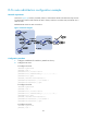
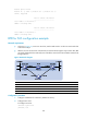
BFD for IS-IS configuration example
Network requirements
• As shown in Figure 44, run IS-IS on Switch A, Switch B and Switch C so that can reach each other
at the network layer.
• After the link over which Switch A and Switch B communicate through the Layer-2 switch fails, BFD
can quickly detect the failure and notify IS-IS of the failure. Switch A and Switch B then communicate
through Switch C.
Figure 44 Network diagram
Device Interface IP address Device Interface IP address
Switch A Vlan-int10 10.1.0.102/24
Switch B
Vlan-int10 10.1.0.100/24
Vlan-int11 11.1.1.1/24
Vlan-int13 13.1.1.1/24
Switch C Vlan-int11 11.1.1.2/24
Vlan-int13 13.1.1.2/24
Configuration procedure
1. Configure IP addresses for interfaces. (Details not shown.)
2. Configure basic IS-IS:
# Configure Switch A.
<SwitchA> system-view
[SwitchA] isis