
R211x-HP Flexfabric 11900 Layer 3 - IP Routing Configuration Guide

302
The output shows that Switch A communicates with Switch B through VLAN-interface 11.
BFD for IPv6 static routes configuration example (indirect next
hop)
Network requirements
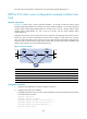
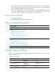
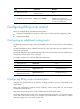
In Figure 76, Switch A has a route to interface Loopback 1 (2::9/128) on Switch B, with the output
interface being VLAN-interface 10. Switch B has a route to interface Loopback 1 (1::9/128) on Switch A,
with the output interface being VLAN-interface 12. Switch D has a route to 1::9/128, with the output
interface being VLAN-interface 10, and a route to 2::9/128, with the output interface being
VLAN-interface 12.
Configure an IPv6 static route to subnet 120::/64 on Switch A, and configure an IPv6 static route to
subnet 121::/64 on Switch B. Enable BFD for both routes. Configure an IPv6 static route to subnet
120::/64 and an IPv6 static route to subnet 121::/64 on both Switch C and Switch D. When the link
between Switch A and Switch B through Switch D fails, BFD can detect the failure immediately and
Switch A and Switch B can communicate through Switch C.
Figure 76 Network diagram
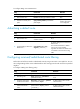
Device Interface IPv6 address
Device
Interface
IPv6 address
Switch A Vlan-int10 12::1/64
Switch B
Vlan-int12 11::2
/
64
Vlan-int11 10::102/64 Vlan-int13 13::1/64
Loop1 1::9/128
Loop1
2::9/128
Switch C Vlan-int11 10::100/64
Switch D
Vlan-int10 12::2/64
Vlan-int13 13::2/64 Vlan-int12 11::1/64
Configuration procedure
1. Configure IPv6 addresses for interfaces. (Details not shown.)
2. Configure IPv6 static routes and BFD:
# Configure IPv6 static routes on Switch A and enable BFD control packet mode for the IPv6 static
route that traverses Switch D.
<SwitchA> system-view
[SwitchA] interface loopback 1
[SwitchA-LoopBack1] bfd min-transmit-interval 500
[SwitchA-LoopBack1] bfd min-receive-interval 500
[SwitchA-LoopBack1] bfd detect-multiplier 9
[SwitchA-LoopBack1] quit
Switch A Switch B
Switch C
BFD
Vlan-int10
Vl
an-i
nt11
Vlan-int11 Vlan-int13
Vlan-
i
nt13
Vlan-int10
121::/64
120::/64
Switch D
Vlan-int12
Vlan-int12
Loop1
1::9/128
Loop1
2::9/128