
R211x-HP Flexfabric 11900 Layer 3 - IP Routing Configuration Guide

341
[SwitchD] display ospfv3 peer
OSPFv3 Process 1 with Router ID 4.4.4.4
Area: 0.0.0.0
-------------------------------------------------------------------------
Router ID Pri State Dead-Time Interface Inst ID
1.1.1.1 100 Full/DR 00:00:30 Vlan100 0
2.2.2.2 0 2-Way/DROther 00:00:37 Vlan200 0
3.3.3.3 2 Full/Backup 00:00:31 Vlan100 0
The output shows that Switch A becomes the DR.
OSPFv3 route redistribution configuration example
Network requirements
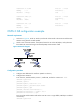
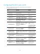
As shown in Figure 81:
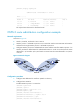
• Switch A, Switch B, and Switch C are in Area 2.
• OSPFv3 process 1 and OSPFv3 process 2 run on Switch B. Switch B communicates with Switch A
and Switch C through OSPFv3 process 1 and OSPFv3 process 2.
• Configure OSPFv3 process 2 to redistribute direct routes and the routes from OSPFv3 process 1 on
Switch B, and set the default metric for redistributed routes to 3. Switch C can then learn the routes
destined for 1::0/64 and 2::0/64, and Switch A cannot learn the routes destined for 3::0/64 or
4::0/64.
Figure 81 Network diagram
Configuration procedure
1. Configure IPv6 addresses for interfaces. (Details not shown.)
2. Configure basic OSPFv3:
# Enable OSPFv3 process 1 on Switch A.
<SwitchA> system-view
[SwitchA] ospfv3 1
[SwitchA-ospfv3-1] router-id 1.1.1.1
[SwitchA-ospfv3-1] quit
[SwitchA] interface vlan-interface 100
[SwitchA-Vlan-interface100] ospfv3 1 area 2
[SwitchA-Vlan-interface100] quit
[SwitchA] interface vlan-interface 200