
R211x-HP Flexfabric 11900 Layer 3 - IP Routing Configuration Guide

345
[SwitchB] ospfv3 1
[SwitchB-ospfv3-1] router-id 2.2.2.2
[SwitchB-ospfv3-1] quit
[SwitchB] interface vlan-interface 100
[SwitchB-Vlan-interface100] ospfv3 1 area 1
[SwitchB-Vlan-interface100] quit
# On Switch C, enable OSPFv3 and set the router ID to 3.3.3.3. (By default, GR helper is enabled
on Switch C.)
<SwitchC> system-view
[SwitchC] ospfv3 1
[SwitchC-ospfv3-1] router-id 3.3.3.3
[SwitchC-ospfv3-1] quit
[SwitchC] interface vlan-interface 100
[SwitchC-Vlan-interface100] ospfv3 1 area 1
[SwitchC-Vlan-interface100] quit
Verifying the configuration
After all switches function correctly, perform a master/backup switchover on Switch A to trigger an
OSPFv3 GR operation.
BFD for OSPFv3 configuration example
Network requirements
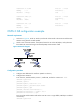
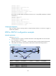
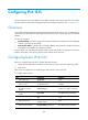
As shown in Figure 83:
• Configure OSPFv3 on Switch A, Switch B and Switch C and configure BFD over the link Switch
A<—>L2 Switch<—>Switch B.
• After the link Switch A<—>L2 Switch<—>Switch B fails, BFD can quickly detect the failure and
notify OSPFv3 of the failure. Then Switch A and Switch B communicate through Switch C.
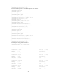
Figure 83 Network diagram
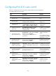
Device Interface IPv6 address
Device
Interface
IPv6 address
Switch A Vlan-int10 2001::1/64 Switch B Vlan-int10 2001::2/64
Vlan-int11 2001:2::1/64
Vlan-int13 2001:3::2/64
Switch C Vlan-int11 2001:2::2/64
Vlan-int13 2001:3::1/64