
R211x-HP Flexfabric 11900 MPLS Configuration Guide

12
Ste
p
Command
Remarks
2. Configure the ingress
node of the static LSP.
static-lsp ingress lsp-name destination
dest-addr { mask | mask-length }
{ nexthop next-hop-addr |
outgoing-interface interface-type
interface-number } out-label out-label
If you specify a next hop for the
static LSP, make sure the ingress
node has an active route to the
specified next hop address.
3. Configure the transit
node of the static LSP.
static-lsp transit lsp-name in-label in-label
{ nexthop next-hop-addr |
outgoing-interface interface-type
interface-number } out-label out-label
If you specify a next hop for the
static LSP, make sure the transit
node has an active route to the
specified next hop address.
4. Configure the egress
node of the static LSP.
static-lsp egress lsp-name in-label in-label
You do not need to configure this
command if the outgoing label
configured on the penultimate
hop of the static LSP is 0 or 3.
Displaying static LSPs
Execute the display command in any view.
Task Command
Display static LSP information. display mpls static-lsp [ lsp-name lsp-name ]
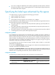
Static LSP configuration example
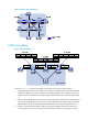
Network requirements
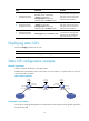
Switch A, Switch B, and Switch C all support MPLS.
Establish static LSPs between Switch A and Switch C, so that subnets 11.1.1.0 / 24 a n d 21.1.1. 0 / 24 c a n
access each other over MPLS.
Figure 8 Network diagram
Configuration considerations
For an LSP, the outgoing label specified on an LSR must be identical with the incoming label specified on
the downstream LSR.
Loop0
2.2.2.9/32
Vlan-int3
20.1.1.1/24
Loop0
3.3.3.9/32
Loop0
1.1.1.9/32
Vlan-int2
10.1.1.1/24
Vlan-int2
10.1.1.2/24
Vlan-int3
20.1.1.2/24
Switch A Switch B Switch C
11.1.1.0/24 21.1.1.0/24
Vlan-int4
11.1.1.1/24
Vlan-int5
21.1.1.1/24