
R211x-HP Flexfabric 11900 MPLS Configuration Guide


192
[SPE2-bgp] address-family vpnv4
[SPE2-bgp-vpnv4] peer 4.4.4.9 upe route-policy hope export
Verifying the configuration
# Verify that CE 1 and CE3 can learn each other's interface routes and can ping each other. Verify that
CE 2 and CE 4 cannot learn each other's interface routes and cannot ping each other. (Details not
shown.)
Configuring OSPF sham links
Network requirements
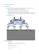
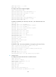
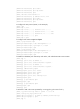
As shown in Figure 55:
• CE 1 and CE 2 belong to VPN 1 and are connected to PE 1 and PE 2, respectively.
• CE 1 and CE 2 are in the same OSPF area.
• VPN traffic between CE 1 and CE 2 is required to be forwarded through the MPLS backbone,
instead of any route in the OSPF area.
Figure 55 Network diagram
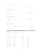
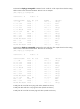
Device Interface IP address Device Interface IP address
CE 1 Vlan-int11 100.1.1.1/24
CE 2
Vlan-int11 120.1.1.1/24
Vlan-int13 20.1.1.1/24
Vlan-int12 30.1.1.2/24
PE 1 Loop0 1.1.1.9/32 PE 2 Loop0 2.2.2.9/32
Loop1 3.3.3.3/32
Loop1
5.5.5.5/32
Vlan-int11 100.1.1.2/24
Vlan-int11 120.1.1.2/24
Vlan-int12 10.1.1.1/24 Vlan-int12 10.1.1.2/24
Switch A Vlan-int11 20.1.1.2/24
Vlan-int12 30.1.1.1/24
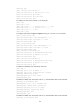
Configuration procedure
1. Configure OSPF on the customer networks:
Configure conventional OSPF on CE 1, Switch A, and CE 2 to advertise subnet addresses of the
interfaces as shown in Figure 55. Exec
ute the display ip routing-table command to verify that CE
1 and CE 2 have learned the OSPF route to VLAN interface 1 of each other. (Details not shown.)
Vlan-int12
Loop0
Loop0
Sham-link
CE 1 Switch A CE 2
PE 2PE 1
Loop1 Loop1
OSPF Area 1
Backdoor link
Vlan-int12
Vlan-int11
Vlan-int11
Vlan-int13
Vlan-int11
Vlan-int11
Vlan-int12 Vlan-int12
Vlan-int13