
R211x-HP Flexfabric 11900 MPLS Configuration Guide

258
Xconnect-group Name: vpna
Peer PW ID In/Out Label Proto Flag Link ID State
192.2.2.2 3 200/100 Static M 0 Up
# Verify that CE 1 and CE 2 can ping each other. (Details not shown.)
Configuring an LDP PW
Network requirements
Create an LDP PW between PE 1 and PE 2 over the backbone so VLAN 10 on CE 1 can communicate
with VLAN 10 on CE 2.
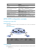
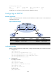
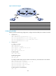
Figure 69 Network diagram
Device Interface IP address Device Interface IP address
PE 1 Loop0 192.2.2.2/32
P
Loop0
192.4.4.4/32
Vlan-int20 10.1.1.1/24
Vlan-int20 10.1.1.2/24
PE 2 Loop0 192.3.3.3/32 Vlan-int30 10.2.2.2/24
Vlan-int30 10.2.2.1/24
Configuration procedure
Before you perform the following configurations, configure VLANs and add ports to VLANs on switches.
1. Configure CE 1.
<CE1> system-view
[CE1] interface ten-gigabitethernet 1/0/1
[CE1-Ten-GigabitEthernet1/0/1] port link-type trunk
[CE1-Ten-GigabitEthernet1/0/1] port trunk permit vlan 10
[CE1-Ten-GigabitEthernet1/0/1] quit
2. Configure PE 1:
# Configure an LSR ID.
<PE1> system-view
[PE1] interface loopback 0
[PE1-LoopBack0] ip address 192.2.2.2 32
[PE1-LoopBack0] quit
[PE1] mpls lsr-id 192.2.2.2
# Enable L2VPN.
[PE1] l2vpn enable