
R211x-HP Flexfabric 11900 MPLS Configuration Guide

262
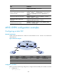
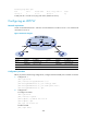
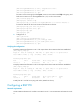
Figure 70 Network diagram
Device Interface IP address
Device
Interface
IP address
PE 1 Loop0 192.2.2.2/32 P Loop0 192.4.4.4/32
Vlan-int20 10.1.1.1/24
Vlan-int20 10.1.1.2/24
PE 2 Loop0 192.3.3.3/32
Vlan-int30 10.2.2.2/24
Vlan-int30 10.2.2.1/24
Configuration procedure
Before you perform the following configurations, configure VLANs and add ports to VLANs on switches.
1. Configure CE 1.
<CE1> system-view
[CE1] interface ten-gigabitethernet 1/0/1
[CE1-Ten-GigabitEthernet1/0/1] port link-type trunk
[CE1-Ten-GigabitEthernet1/0/1] port trunk permit vlan 10
[CE1-Ten-GigabitEthernet1/0/1] quit
2. Configure PE 1:
# Configure an LSR ID.
<PE1> system-view
[PE1] interface loopback 0
[PE1-LoopBack0] ip address 192.2.2.2 32
[PE1-LoopBack0] quit
[PE1] mpls lsr-id 192.2.2.2
# Enable L2VPN.
[PE1] l2vpn enable
# Enable LDP globally.
[PE1] mpls ldp
[PE1-ldp] quit
# Configure VLAN-interface 20 (the interface connected to P), and enable LDP on the interface.
[PE1] interface vlan-interface 20
[PE1-Vlan-interface20] ip address 10.1.1.1 24
[PE1-Vlan-interface20] mpls enable
[PE1-Vlan-interface20] mpls ldp enable
[PE1-Vlan-interface20] quit
# Enable OSPF for LSP establishment.
[PE1] ospf