
R211x-HP Flexfabric 11900 MPLS Configuration Guide


312
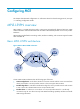
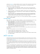
Figure 82 Network diagram for the MCE function
As shown in Figure 82, the MCE device creates a routing table for each VPN. VLAN interface 2 binds to
VPN 1 and VLAN-interface 3 binds to VPN 2. When receiving a route, the MCE device determines the
source of the routing information according to the number of the receiving interface, and then adds it to
the corresponding routing table. The MCE connects to PE 1 through a trunk link that permits packets
tagged with VLAN 2 or VLAN 3. PE 1 determines the VPN that a received packet belongs to according
to the VLAN tag of the packet, and sends the packet through the corresponding tunnel.
You can configure static routes, RIP, OSPF, IS-IS, EBGP, or IBGP between an MCE and a VPN site and
between an MCE and a PE.
NOTE:
To implement dynamic IP assi
g
nment for DHCP clients in private networks, you can confi
g
ure DHCP server
or DHCP relay agent on the MCE. When the MCE functions as the DHCP server, the IP addresses assi
g
ned
to different private networks cannot overlap.
MCE configuration task list
Tasks at a
g
lance
Configuring VPN instances:
1. (Required.) Creating a VPN instance
2. (R
equired.) Associating a VPN instance with an interface
3. (Optional.) Configuring route related attributes for a VPN instance
Configuring routing on an MCE:
• (Required.) Configuring routing between an MCE and a VPN site
• (Required.) Configuring routing between an MCE and a PE