
R211x-HP Flexfabric 11900 MPLS Configuration Guide

326
MCE configuration examples
Configuring the MCE that uses OSPF to advertise VPN routes to
the PE
Network requirements
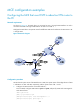
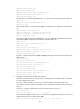
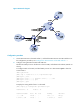
As shown in Figure 83, the MCE device is connected to VPN 1 through VLAN-interface 10 and is
connected with VPN 2 through VLAN-interface 20. RIP runs in VPN 2.
Configure the MCE device to separate routes from different VPNs and to advertise the VPN routes to PE
1 through OSPF.
Figure 83 Network diagram
Configuration procedure
Assume that the system name of the MCE device is MCE, the system names of the edge devices of VPN
1 and VPN 2 are VR1 and VR2, respectively, and the system name of PE 1 is PE1.
1. Configure the VPN instances on the MCE and PE 1:
# On the MCE, configure VPN instances vpn1 and vpn2, and specify an RD and route targets for
each VPN instance.
<MCE> system-view
[MCE] ip vpn-instance vpn1
[MCE-vpn-instance-vpn1] route-distinguisher 10:1
[MCE-vpn-instance-vpn1] vpn-target 10:1