
R211x-HP Flexfabric 11900 MPLS Configuration Guide

30
Task Command
Display LDP discovery information.
display mpls ldp discovery [ vpn-instance vpn-instance-name ]
[ interface interface-type interface-number | peer peer-lsr-id |
targeted-peer peer-lsr-id ] [ verbose ]
Display LDP FEC-label mapping
information.
display mpls ldp fec [ vpn-instance vpn-instance-name ]
[ destination-address mask-length | summary ]
Display LDP interface information. display mpls ldp interface [ interface-type interface-number ]
Display LDP LSP information.
display mpls ldp lsp [ vpn-instance vpn-instance-name ]
[ destination-address mask-length ]
Display LDP running parameters. display mpls ldp parameter [ vpn-instance vpn-instance-name ]
Display LDP peer and session
information.
display mpls ldp peer [ vpn-instance vpn-instance-name ]
[ peer-lsr-id ] [ verbose ]
Display LDP summary information. display mpls ldp summary [ all | vpn-instance vpn-instance-name ]
LDP configuration examples
LDP LSP configuration example
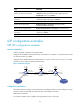
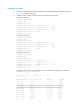
Network requirements
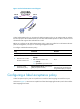
Switch A, Switch B, and Switch C all support MPLS.
Configure LDP to establish LSPs between Switch A and Switch C, so subnets 11.1.1.0 / 24 a n d 21.1.1. 0 / 24
can reach each other over MPLS.
Configure LDP to establish LSPs for only destinations 1.1.1.9/32, 2.2.2.9/32, 3.3.3.9/32, 11.1.1. 0 / 24 ,
and 21.1.1.0/24 on Switch A, Switch B, and Switch C.
Figure 16 Network diagram
Configuration considerations
LDP assigns labels according to routing information. To establish LDP LSPs, you must configure a routing
protocol to make sure the LSRs can reach each other. This example uses OSPF.
Enable LDP on each LSR.
To control the number of LSPs, configure an LSP generation policy on each LSR.
Loop0
2.2.2.9/32
Vlan-int3
20.1.1.1/24
Loop0
3.3.3.9/32
Loop0
1.1.1.9/32
Vlan-int2
10.1.1.1/24
Vlan-int2
10.1.1.2/24
Vlan-int3
20.1.1.2/24
Switch A Switch B Switch C
11.1.1.0/24 21.1.1.0/24
Vlan-int4
11.1.1.1/24
Vlan-int5
21.1.1.1/24