
R211x-HP Flexfabric 11900 MPLS Configuration Guide
35
Configuration considerations
1. Configure a routing protocol on each switch to make sure that the switches can reach each other.
This example uses OSPF.
2. Enable LDP on each switch.
3. Configure LSP generation policies, so LDP establishes LSPs only for the routes 11.1.1.0/24 and
21.1.1.0/24.
4. Configure label acceptance policies, so LDP sets up LSPs only over the link Switch A—Switch
B—Switch C, as follows:
{ Switch A accepts only the label mapping for FEC 21.1.1.0/24 received from Switch B. Switch A
denies the label mapping for FEC 21.1.1.0/24 received from Switch D.
{ Switch C accepts only the label mapping for FEC 11.1.1.0 / 24 r e c e i ve d f r o m Swi t c h B . Swi t c h C
denies the label mapping for FEC 11.1.1.0 / 24 r e c e i ve d f r o m Swi t c h D.
Configuration procedure
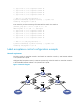
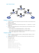
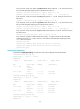
1. Configure IP addresses and masks for interfaces, including the loopback interfaces, as shown
in Figure 17. (Details not
shown.)
2. Configure OSPF on each switch to ensure IP connectivity between them. (Details not shown.)
3. Enable MPLS and LDP:
# Configure Switch A.
<SwitchA> system-view
[SwitchA] mpls lsr-id 1.1.1.9
[SwitchA] mpls ldp
[SwitchA-ldp] quit
[SwitchA] interface vlan-interface 2
[SwitchA-Vlan-interface2] mpls enable
[SwitchA-Vlan-interface2] mpls ldp enable
[SwitchA-Vlan-interface2] quit
[SwitchA] interface vlan-interface 6
[SwitchA-Vlan-interface6] mpls enable
[SwitchA-Vlan-interface6] mpls ldp enable
[SwitchA-Vlan-interface6] quit
# Configure Switch B.
<SwitchB> system-view
[SwitchB] mpls lsr-id 2.2.2.9
[SwitchB] mpls ldp
[SwitchB-ldp] quit
[SwitchB] interface vlan-interface 2
[SwitchB-Vlan-interface2] mpls enable
[SwitchB-Vlan-interface2] mpls ldp enable
[SwitchB-Vlan-interface2] quit
[SwitchB] interface vlan-interface 3
[SwitchB-Vlan-interface3] mpls enable
[SwitchB-Vlan-interface3] mpls ldp enable
[SwitchB-Vlan-interface3] quit
# Configure Switch C.
<SwitchC> system-view