
R211x-HP Flexfabric 11900 MPLS Configuration Guide

62
Route Pinning : Disabled
Retry Limit : 10 Retry Interval : 2 sec
Reoptimization : Disabled Reoptimization Freq : -
Backup Type : None Backup LSP ID : -
Auto Bandwidth : Disabled Auto Bandwidth Freq : -
Min Bandwidth : - Max Bandwidth : -
Collected Bandwidth : -
# Execute the display ip routing-table command on Switch A. The output shows a static route entry with
interface Tunnel 1 as the output interface.
Bidirectional MPLS TE tunnel configuration example
Network requirements
Switch A, Switch B, Switch C, and Switch D all run IS-IS.
Use RSVP-TE to establish a bidirectional MPLS TE tunnel between Switch A and Switch D.
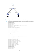
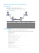
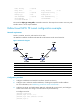
Figure 22 Network diagram
Device Interface IP address Device Interface IP address
Switch A Loop0 1.1.1.9/32
Switch D
Loop0
4.4.4.9/32
Vlan-int1 10.1.1.1/24
Vlan-int3
30.1.1.2/24
Switch B Loop0 2.2.2.9/32 Switch C Loop0 3.3.3.9/32
Vlan-int1 10.1.1.2/24
Vlan-int3
30.1.1.1/24
Vlan-int2 20.1.1.1/24
Vlan-int2
20.1.1.2/24
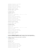
Configuration procedure
1. Configure IP addresses and masks for interfaces. (Details not shown.)
2. Configure IS-IS to advertise interface addresses, including the loopback interface address.
For more information, see "Establishing an MPLS TE tun
nel with RSVP-TE."
3. Configure an LSR ID, and enable MPLS, MPLS TE, and RSVP-TE on each switch, and configure
Switch A and Switch D to assign a non-null label to the penultimate hop:
# Configure Switch A.
<SwitchA> system-view
[SwitchA] mpls lsr-id 1.1.1.9
[SwitchA] mpls label advertise non-null
[SwitchA] mpls te