
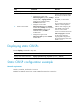
R211x-HP Flexfabric 11900 MPLS Configuration Guide
75
[SwitchC-isis-1] network-entity 00.0005.0000.0000.0003.00
[SwitchC-isis-1] quit
[SwitchC] interface vlan-interface 2
[SwitchC-Vlan-interface2] isis enable 1
[SwitchC-Vlan-interface2] quit
[SwitchC] interface loopback 0
[SwitchC-LoopBack0] isis enable 1
[SwitchC-LoopBack0] quit
# Execute the display ip routing-table command on each switch. The output shows that the
switches have learned the routes to one another, including the routes to the loopback interfaces.
3. Configure an LSR ID, and enable MPLS and MPLS TE:
# Configure Switch A.
[SwitchA] mpls lsr-id 1.1.1.1
[SwitchA] mpls te
[SwitchA-te] quit
[SwitchA] interface vlan-interface 1
[SwitchA-Vlan-interface1] mpls enable
[SwitchA-Vlan-interface1] mpls te enable
[SwitchA-Vlan-interface1] quit
# Configure Switch B.
[SwitchB] mpls lsr-id 2.2.2.2
[SwitchB] mpls te
[SwitchB-te] quit
[SwitchB] interface vlan-interface 1
[SwitchB-Vlan-interface1] mpls enable
[SwitchB-Vlan-interface1] mpls te enable
[SwitchB-Vlan-interface1] quit
[SwitchB] interface vlan-interface 2
[SwitchB-Vlan-interface2] mpls enable
[SwitchB-Vlan-interface2] mpls te enable
[SwitchB-Vlan-interface2] quit
# Configure Switch C.
[SwitchC] mpls lsr-id 3.3.3.3
[SwitchC] mpls te
[SwitchC-te] quit
[SwitchC] interface vlan-interface 2
[SwitchC-Vlan-interface2] mpls enable
[SwitchC-Vlan-interface2] mpls te enable
[SwitchC-Vlan-interface2] quit
4. On Switch A, configure MPLS TE tunnel interface Tunnel 0, specify the tunnel destination address
as the LSR ID of Switch C, and configure MPLS TE to use a static CRLSP to establish the tunnel.
[SwitchA] interface tunnel 0 mode mpls-te
[SwitchA-Tunnel0] ip address 6.1.1.1 255.255.255.0
[SwitchA-Tunnel0] destination 3.3.3.3
[SwitchA-Tunnel0] mpls te signaling static
[SwitchA-Tunnel0] quit
5. Create a static CRLSP: