
R211x-HP Flexfabric 11900 Network Management and Monitoring Configuration Guide


44
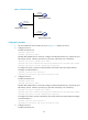
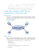
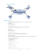
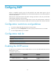
Figure 16 Network diagram
Configuration procedure
1. Set the IP address for each interface as shown in Figure 16. (Details not shown.)
2. Configure Device A:
# Enable the NTP service.
<DeviceA> system-view
[DeviceA] ntp-service enable
# Specify the local clock as the reference source, with the stratum level 2.
[DeviceA] ntp-service refclock-master 2
3. Configure Device B:
# Enable the NTP service.
<DeviceB> system-view
[DeviceB] ntp-service enable
# Enable NTP authentication on Device B.
[DeviceB] ntp-service authentication enable
# Set an authentication key, and input the key in plain text.
[DeviceB] ntp-service authentication-keyid 42 authentication-mode md5 simple
aNiceKey
# Specify the key as a trusted key.
[DeviceB] ntp-service reliable authentication-keyid 42
# Specify Device A as the NTP server of Device B, and associate the server with key 42.
[DeviceB] ntp-service unicast-server 1.0.1.11 authentication-keyid 42
Before Device B can synchronize its clock to that of Device A, enable NTP authentication for
Device A.
4. Configure NTP authentication on Device A:
# Enable NTP authentication.
[DeviceA] ntp-service authentication enable
# Set an authentication key, and input the key in plain text.
[DeviceA] ntp-service authentication-keyid 42 authentication-mode md5 simple
aNiceKey
# Specify the key as a trusted key.
[DeviceA] ntp-service reliable authentication-keyid 42
5. Verify the configuration:
# Display the NTP status of Device B after clock synchronization.
[DeviceB] display ntp-service status
Clock status: synchronized
Clock stratum: 3
System peer: 1.0.1.11
Local mode: client