HP FlexFabric 11900 Switch Series Security Configuration Guide Part number: 5998-5263 Software version: Release 2111 and later Document version: 6W100-20140110
Legal and notice information © Copyright 2014 Hewlett-Packard Development Company, L.P. No part of this documentation may be reproduced or transmitted in any form or by any means without prior written consent of Hewlett-Packard Development Company, L.P. The information contained herein is subject to change without notice.
Contents Configuring AAA ························································································································································· 1 Overview············································································································································································ 1 RADIUS ·············································································································································
802.1X overview ······················································································································································· 61 802.1X architecture ······················································································································································· 61 Controlled/uncontrolled port and port authorization status ······················································································ 61 802.
Configuring port security ··········································································································································· 88 Overview········································································································································································· 88 Port security features ···········································································································································
Destroying a local key pair ········································································································································· 120 Configuring a peer public key···································································································································· 121 Importing a peer host public key from a public key file·················································································· 121 Entering a peer public key ·······
Configuring SNMP notifications for IKE ···················································································································· 160 Displaying and maintaining IKE ································································································································· 160 Main mode IKE with pre-shared key authentication configuration example ························································· 161 Network requirements ·································
IP source guard configuration task list ······················································································································· 206 Configuring the IPv4 source guard function ·············································································································· 207 Enabling IPv4 source guard on an interface ···································································································· 207 Configuring a static IPv4 source guard bin
uRPF operation ····················································································································································· 234 Network application ··········································································································································· 237 Configuring uRPF·························································································································································· 237 Disp
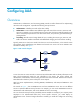
Configuring AAA Overview Authentication, Authorization, and Accounting (AAA) provides a uniform framework for implementing network access management. It specifies the following security functions: • Authentication—Identifies users and verifies their validity. • Authorization—Grants different users different rights and controls their access to resources and services.
The device performs dynamic password authentication. RADIUS Remote Authentication Dial-In User Service (RADIUS) is a distributed information interaction protocol that uses a client/server model. It can protect networks against unauthorized access and is often used in network environments that require both high security and remote user access. The RADIUS authorization process is combined with the RADIUS authentication process, and user authorization information is piggybacked in authentication responses.
Basic RADIUS packet exchange process Figure 3 illustrates the interactions between a user host, the RADIUS client, and the RADIUS server. Figure 3 Basic RADIUS packet exchange process RADIUS uses in the following workflow: 1. The host sends a connection request that includes the user's username and password to the RADIUS client. 2. The RADIUS client sends an authentication request (Access-Request) to the RADIUS server.
RADIUS packet format RADIUS uses UDP to transmit packets. To ensure smooth packet exchange between the RADIUS server and the client, RADIUS uses a series of mechanisms, including the timer mechanism, the retransmission mechanism, and the backup server mechanism. Figure 4 shows the RADIUS packet format. Figure 4 RADIUS packet format Descriptions of the fields are as follows: The Code field (1 byte long) indicates the type of the RADIUS packet. Table 1 gives the main values and their meanings.
• The Authenticator field (16 bytes long) is used to authenticate responses from the RADIUS server and to encrypt user passwords. There are two types of authenticators: request authenticator and response authenticator. • The Attributes field (variable in length) includes specific authentication, authorization, and accounting information. This field can contain multiple attributes, each with three sub-fields: { Type—Type of the attribute.
No. Attribute No.
Figure 5 Format of attribute 26 HWTACACS HW Terminal Access Controller Access Control System (HWTACACS) is an enhanced security protocol based on TACACS (RFC 1492). HWTACACS is similar to RADIUS, and uses a client/server model for information exchange between the NAS and the HWTACACS server. HWTACACS typically provides AAA services for PPP, VPDN, and terminal users. In a typical HWTACACS scenario, terminal users need to log in to the NAS.
Figure 6 Basic HWTACACS packet exchange process for a Telnet user Host HWTACACS client HWTACACS server 1) The user tries to log in 2) Start-authentication packet 3) Authentication response requesting the username 4) Request for username 5) The user enters the username 6) Continue-authentication packet with the username 7) Authentication response requesting the password 8) Request for password 9) The user enters the password 10) Continue-authentication packet with the password 11) Response indicating succ
9. The user enters the password. 10. After receiving the login password, the HWTACACS client sends the HWTACACS server a continue-authentication packet that includes the login password. 11. If the authentication succeeds, the HWTACACS server sends back an authentication response to indicate that the user has passed authentication. 12. The HWTACACS client sends a user authorization request packet to the HWTACACS server. 13.
1. An LDAP client uses the LDAP server administrator DN to bind with the LDAP server, establishes a connection to the server, and obtains the right to search. 2. The LDAP client uses the username in the authentication information of a user to construct search conditions, searches for the user in the specified root directory of the server, and obtains a user DN list. 3. The LDAP client uses each user DN in the obtained user DN list and the user's password to bind with the LDAP server.
4. The LDAP server processes the request. If the bind operation is successful, the LDAP server sends an acknowledgement to the LDAP client. 5. The LDAP client sends a user DN search request with the username of the Telnet user to the LDAP server. 6. After receiving the request, the LDAP server searches for the user DN by the base DN, search scope, and filtering conditions. If a match is found, the LDAP server sends a response to notify the LDAP client of the successful search.
NOTE: The device also provides authentication modules (such as 802.1X) for implementation of user authentication management policies. If you configure these authentication modules, the ISP domains for users of the access types depend on the configuration of the authentication modules. AAA methods AAA supports configuring different authentication, authorization, and accounting methods for different types of users in an ISP domain.
• Remote accounting—The NAS works with a RADIUS server or HWTACACS server for accounting. You can configure backup methods to be used when the remote server is not available. In addition, the device provides the following login services to enhance device security: • Command authorization—Enables the NAS to let the authorization server determine whether a command entered by a login user is permitted, and allow login users to execute only authorized commands.
• RFC 1492, An Access Control Protocol, Sometimes Called TACACS • RFC 1777, Lightweight Directory Access Protocol • RFC 2251, Lightweight Directory Access Protocol (v3) RADIUS attributes Commonly used standard RADIUS attributes No. Attribute Description 1 User-Name Name of the user to be authenticated. 2 User-Password User password for PAP authentication, only present in Access-Request packets when PAP authentication is used.
No. Attribute Description Type of the Accounting-Request packet. Possible values include: 40 Acct-Status-Type • • • • • • • • 1—Start. 2—Stop. 3—Interim-Update. 4—Reset-Charge. 7—Accounting-On. (Defined in the 3rd Generation Partnership Project.) 8—Accounting-Off. (Defined in the 3rd Generation Partnership Project.) 9 to 14—Reserved for tunnel accounting. 15—Reserved for failed. Authentication method used by the user. Possible values include: 45 Acct-Authentic 60 CHAP-Challenge • 1—RADIUS.
No. Sub-attribute Description Operation for the session, used for session control. Possible values include: 20 24 Command Control_Identifier • • • • • 1—Trigger-Request. 2—Terminate-Request. 3—SetPolicy. 4—Result. 5—PortalClear. Identification for retransmitted packets. For retransmitted packets from the same session, this attribute must be the same value. For retransmitted packets from different sessions, this attribute does not have to be the same value.
No. Sub-attribute Description 206 Output-Interval-Gigawords Amount of bytes output within an accounting interval, in units of 4G bytes. 207 Backup-NAS-IP Backup source IP address for sending RADIUS packets. 255 Product_ID Product name. FIPS compliance The device supports the FIPS mode that complies with NIST FIPS 140-2 requirements. Support for features, commands, and parameters might differ in FIPS mode (see "Configuring FIPS") and non-FIPS mode.
Tasks at a glance (Required.) Perform at least one of the following tasks to configure local users or AAA schemes: • • • • Configuring local users Configuring RADIUS schemes Configuring HWTACACS schemes Configuring LDAP schemes (Required.) Configure AAA methods for ISP domains: 1. (Required.) Creating an ISP domain 2. (Optional.) Configuring ISP domain attributes 3. (Required.
• Binding attributes—Binding attributes control the scope of users, and are checked during local authentication of a user. If the attributes of a user do not match the binding attributes configured for the local user account, the user cannot pass authentication. Binding attributes include the IP address, access port, MAC address, and native VLAN. For support and usage information about binding attributes, see "Configuring local user attributes.
Step Command Remarks 1. Enter system view. system-view N/A 2. Add a local user and enter local user view. local-user user-name [ class { manage | network } ] By default, no local user exists. • For a network access user: password { cipher | simple } password 3. (Optional.) Configure a password for the local user.
Step Command Remarks The following default settings apply: • No authorization ACL, idle timeout period, or authorized VLAN is configured for local users. • FTP, SFTP, or SCP users have the root directory of the NAS set as the working directory, but they do not have the access permission to the root directory. • The network-operator user role is 8. (Optional.) Configure authorization attributes for the local user.
Step Command Remarks 10. (Optional.) Assign the local user to a user group. group group-name By default, a local user belongs to the default user group system. Configuring user group attributes User groups simplify local user configuration and management. A user group comprises a group of local users and has a set of local user attributes. You can configure local user attributes for a user group to implement centralized user attributes management for the local users in the group.
Task Command Display the local user configuration and online user statistics. display local-user [ class { manage | network } | idle-cut { disable | enable } | service-type { ftp | lan-access | ssh | telnet | terminal } | state { active | block } | user-name user-name | vlan vlan-id ] Display the user group configuration.
Specifying the RADIUS authentication servers A RADIUS authentication server completes authentication and authorization together, because authorization information is piggybacked in authentication responses sent to RADIUS clients. You can specify one primary authentication server and up to 16 secondary authentication servers for a RADIUS scheme.
Step Command Remarks • Specify the primary RADIUS 3. 4. accounting server: primary accounting { ipv4-address | ipv6 ipv6-address } [ port-number | key { cipher | simple } string | vpn-instance vpn-instance-name ] * Configure at least one command. By default, no accounting server is specified. Specify RADIUS accounting servers. • Specify a secondary RADIUS Two accounting servers in a scheme, primary or secondary, cannot have the same combination of IP address, port number, and VPN. (Optional.
Step 3. Specify a VPN for the RADIUS scheme. Command Remarks vpn-instance vpn-instance-name By default, a RADIUS scheme belongs to the public network. Setting the username format and traffic statistics units A username is typically in the format userid@isp-name, where isp-name represents the user's ISP domain name. By default, the ISP domain name is included in a username. However, older RADIUS servers might not recognize usernames that contain the ISP domain names.
Setting the status of RADIUS servers To control the RADIUS servers with which the device communicates when the current servers are no longer available, set the status of RADIUS servers to blocked or active. You can specify one primary RADIUS server and multiple secondary RADIUS servers, with the secondary servers functioning as the backup of the primary servers.
Step Command Remarks • Set the status of the primary RADIUS authentication server: state primary authentication { active | block } • Set the status of the primary RADIUS accounting server: state primary accounting { active | block } • Set the status of a secondary RADIUS Set the RADIUS server status. 3.
To specify a source IP address for a specific RADIUS scheme: Step Command Remarks 1. Enter system view. system-view N/A 2. Enter RADIUS scheme view. radius scheme radius-scheme-name N/A nas-ip { ipv4-address | ipv6 ipv6-address } By default, the source IP address specified by the radius nas-ip command in system view is used. If the source IP address is not specified, the IP address of the outbound interface is used. 3. Specify a source IP address for outgoing RADIUS packets.
Step Command Remarks 1. Enter system view. system-view N/A 2. Enter RADIUS scheme view. radius scheme radius-scheme-name N/A 3. Set the RADIUS server response timeout timer. timer response-timeout seconds The default setting is 3 seconds. 4. Set the quiet timer for the servers. timer quiet minutes The default setting is 5 minutes. 5. Set the real-time accounting timer. timer realtime-accounting minutes The default setting is 12 minutes.
Step Command Specify a security policy server. 3. Remarks security-policy-server { ipv4-address | ipv6 ipv6-address } [ vpn-instance vpn-instance-name ] By default, no security policy server is specified for a scheme. You can specify up to eight security policy servers for a RADIUS scheme.
Tasks at a glance (Required.) Specifying the HWTACACS authentication servers (Optional.) Specifying the HWTACACS authorization servers (Optional.) Specifying the HWTACACS accounting servers (Required.) Specifying the shared keys for secure HWTACACS communication (Optional.) Specifying a VPN for the scheme (Optional.) Setting the username format and traffic statistics units (Optional.) Specifying the source IP address for outgoing HWTACACS packets (Optional.) Setting HWTACACS timers (Optional.
Step Command Remarks • Specify the primary HWTACACS 3. Specify HWTACACS authentication servers.
function as the primary accounting server of one scheme and as the secondary accounting server of another scheme at the same time. HWTACACS does not support accounting for FTP users. To specify HWTACACS accounting servers for an HWTACACS scheme: Step Command Remarks 1. Enter system view. system-view N/A 2. Enter HWTACACS scheme view. hwtacacs scheme hwtacacs-scheme-name N/A • Specify the primary HWTACACS 3. Specify HWTACACS accounting servers.
Step Command Remarks 1. Enter system view. system-view N/A 2. Enter HWTACACS scheme view. hwtacacs scheme hwtacacs-scheme-name N/A 3. Specify a VPN for the HWTACACS scheme. vpn-instance vpn-instance-name By default, an HWTACACS scheme belongs to the public network. Setting the username format and traffic statistics units A username is typically in the format userid@isp-name, where isp-name represents the user's ISP domain name. By default, the ISP domain name is included in a username.
1. The source IP address specified for the HWTACACS scheme. 2. The source IP address specified in system view for the VPN or public network, depending on where the HWTACACS server resides. 3. The IP address of the outbound interface specified by the route. To specify a source IP address for all HWTACACS schemes of a VPN or the public network: Step Command Remarks 1. Enter system view. system-view N/A 2. Specify a source IP address for outgoing HWTACACS packets.
{ Tries to communicate with a secondary server in active state that has the highest priority. If the secondary server is unreachable, the device does the following: • { Changes the server's status to blocked. { Starts a quiet timer for the server. { Tries to communicate with the next secondary server in active state that has the highest priority. • The search process continues until the device finds an available secondary server or has checked all secondary servers in active state.
Task Command Clear HWTACACS statistics. reset hwtacacs statistics { accounting | all | authentication | authorization } Configuring LDAP schemes Configuration task list Tasks at a glance Configuring an LDAP server: • • • • • • (Required.) Creating an LDAP server (Required.) Configuring the IP address of the LDAP server (Optional.) Specifying the LDAP version (Optional.) Setting the LDAP server timeout period (Required.) Configuring administrator attributes (Required.
Step Command Remarks 1. Enter system view. system-view N/A 2. Enter LDAP server view. ldap server server-name N/A 3. Specify the LDAP version. protocol-version { v2 | v3 } By default, LDAPv3 is used. A Microsoft LDAP server supports only LDAPv3.
• Search scope • Username attribute • Username format • User object class If the LDAP server contains many directory levels, a user DN search starting from the root directory can take a long time. To improve efficiency, you can change the start point by specifying the search base DN. To configure LDAP user attributes: Step Command Remarks 1. Enter system view. system-view N/A 2. Enter LDAP server view. ldap server server-name N/A 3. Specify the user search base DN.
Displaying and maintaining LDAP Execute the display command in any view. Task Command Display the configuration of LDAP schemes. display ldap scheme [ scheme-name ] Configuring AAA methods for ISP domains You configure AAA methods for an ISP domain by referencing configured AAA schemes in ISP domain view. Each ISP domain has a set of system-defined AAA methods, which are local authentication, local authorization, and local accounting.
Step Command Remarks 3. Return to system view. quit N/A 4. (Optional.) Specify the default ISP domain. domain default enable isp-name By default, the default ISP domain is the system-defined ISP domain system. Configuring ISP domain attributes In an ISP domain, you can configure the following attributes: • Domain status—By placing the ISP domain in active or blocked state, you allow or deny network service requests from users in the domain.
To specify a scheme for user role authentication, make sure the user role is in the format of level-n. If an HWTACACS scheme is specified, the device uses the entered username for role authentication. If a RADIUS scheme is specified, the device uses the username $enabn$ on the RADIUS server for role authentication, where n is the same as that in the target user role level-n. • Configuration procedure To configure authentication methods for an ISP domain: Step Command Remarks 1. Enter system view.
To use a RADIUS scheme as the authorization method, reference the same RADIUS scheme that is configured as the authentication method for the ISP domain. If an invalid RADIUS scheme is specified as the authorization method, RADIUS authentication and authorization fail. • Configuration procedure To configure authorization methods for an ISP domain: Step Command Remarks 1. Enter system view. system-view N/A 2. Enter ISP domain view.
Local accounting does not provide statistics for charging. It only counts and controls the number of concurrent users who use the same local user account. The threshold is configured by using the access-limit command. • Configuration procedure To configure accounting methods for an ISP domain: Step Command Remarks 1. Enter system view. system-view N/A 2. Enter ISP domain view. domain isp-name N/A Specify the default accounting method for all types of users.
Setting the maximum number of concurrent login users Perform this task to set the maximum number of concurrent users who can log on to the device through a specific protocol, regardless of their authentication methods: no authentication, local authentication, or remote authentication. To set the maximum number of concurrent login users: Step Enter system view. 1. Command Remarks system-view N/A • In non-FIPS mode: Set the maximum number of concurrent login users. 2.
Figure 11 Network diagram Configuration procedure 1. Configure the HWTACACS server: # On the HWTACACS server, set the shared keys for secure communication with the switch to expert, add an account for the SSH user, and specify the password. (Details not shown.) 2. Configure the switch: # Assign IP addresses to the interfaces. (Details not shown.) # Create an HWTACACS scheme. system-view [Switch] hwtacacs scheme hwtac # Specify the primary authentication server.
# Enable the SSH service. [Switch] ssh server enable # Enable scheme authentication for user lines VTY 0 through VTY 63. [Switch] line vty 0 63 [Switch-line-vty0-63] authentication-mode scheme [Switch-line-vty0-63] quit # Enable the default user role feature to assign authenticated SSH users the default user role network-operator.
2. Configure the RADIUS server. (Details not shown.) 3. Configure the switch: # Assign IP addresses to interfaces. (Details not shown.) # Create local RSA and DSA key pairs. system-view [Switch] public-key local create rsa [Switch] public-key local create dsa # Enable the SSH service. [Switch] ssh server enable # Enable scheme authentication for user lines VTY 0 through VTY 63.
Verifying the configuration When the user initiates an SSH connection to the switch and enter the username hello@bbb and the correct password, the user successfully logs in and can use the commands for the network-operator user role. Authentication and authorization for SSH users by a RADIUS server Network requirements As shown in Figure 13, the RADIUS authentication and authorization server runs on IMC. Configure the switch to use the RADIUS server for SSH user authentication and authorization.
c. Select the service type Device Management Service. d. Select the access device type HP. e. Select the access device from the device list or manually add the access device (with the IP address 10.1.1.2). f. Leave the default settings for other parameters and click OK.
Figure 15 Adding an account for device management 2. Configure the switch: # Assign an IP address to VLAN-interface 2, the SSH user access interface. system-view [Switch] interface vlan-interface 2 [Switch-Vlan-interface2] ip address 192.168.1.70 255.255.255.0 [Switch-Vlan-interface2] quit # Assign an IP address to VLAN-interface 3, through which the switch communicates with the server. [Switch] interface vlan-interface 3 [Switch-Vlan-interface3] ip address 10.1.1.2 255.255.255.
# Create a RADIUS scheme. [Switch] radius scheme rad # Specify the primary authentication server. [Switch-radius-rad] primary authentication 10.1.1.1 1812 # Set the shared key for secure communication with the server to expert in plain text. [Switch-radius-rad] key authentication simple expert # Include the domain names in usernames sent to the RADIUS server.
Figure 16 Network diagram Configuration procedure 1. Configure the LDAP server: NOTE: In this example, the LDAP server runs Microsoft Windows 2003 Server Active Directory. # Add a user named aaa and set the password to ldap!123456. a. On the LDAP server, select Start > Control Panel > Administrative Tools, and double-click Active Directory Users and Computers to display the Active Directory Users and Computers window. b. From the navigation tree, click Users under the ldap.com node. c.
e. In the dialog box, enter the password ldap!123456, select options as needed, and click Next. Figure 18 Setting the user's password f. Click OK. # Add user aaa to group Users. g. From the navigation tree, click Users under the ldap.com node. h. On the right pane, right-click aaa and select Properties. i. In the dialog box, click the Member Of tab, select Domain Users, and click Add.
Figure 19 Modifying user properties d. In the Select Groups dialog box, enter Users in the Enter the object names to select field, and click OK. User aaa is added to group Users. Figure 20 Adding user aaa to group Users # Set the administrator password to admin!123456. a. From the user list on the right pane, right-click Administrator and select Set Password. b. In the dialog box, enter the administrator password. (Details not shown.) 2.
# Assign an IP address to VLAN-interface 2, the SSH user access interface. system-view [Switch] interface vlan-interface 2 [Switch-Vlan-interface2] ip address 192.168.1.70 24 [Switch-Vlan-interface2] quit # Assign an IP address to VLAN-interface 3, through which the switch communicates with the server. [Switch] interface vlan-interface 3 [Switch-Vlan-interface3] ip address 10.1.1.2 24 [Switch-Vlan-interface3] quit # Create local RSA and DSA key pairs.
Verifying the configuration When the user initiates an SSH connection to the switch and enter the username aaa@bbb and password ldap!123456, the user successfully logs in and can use the commands for the network-operator user role. Troubleshooting RADIUS RADIUS authentication failure Symptom User authentication always fails. Analysis Possible reasons include: • A communication failure exists between the NAS and the RADIUS server.
Solution Check that: • The link between the NAS and the RADIUS server work well at both the physical and data link layers. • The IP address of the RADIUS server is correctly configured on the NAS. • The authentication and accounting UDP port numbers configured on the NAS are the same as those of the RADIUS server. • The RADIUS server's authentication and accounting port numbers are available.
• The administrator DN or password is not configured. • Some user attributes (for example, the username attribute) configured on the NAS are not consistent with those configured on the server. • No user search base DN is specified for the LDAP scheme. Solution Check that: • The NAS and the LDAP server can ping each other. • The IP address and port number of the LDAP server configured on the NAS match those of the server.
802.1X overview 802.1X is a port-based network access control protocol initially proposed for securing WLANs. It has also been widely used on Ethernet networks for access control. 802.1X controls network access by authenticating the devices connected to 802.1X-enabled LAN ports. 802.1X architecture 802.1X operates in the client/server model. It includes three entities: the client (the supplicant), the network access device (the authenticator), and the authentication server. Figure 21 802.
− Performs unidirectional traffic control to deny traffic from the client. The HP devices support only unidirectional traffic control. Figure 22 Authorization state of a controlled port 802.1X-related protocols 802.1X uses the Extensible Authentication Protocol (EAP) to transport authentication information for the client, the network access device, and the authentication server. EAP is an authentication framework that uses the client/server model.
• Code—Type of the EAP packet. Options include Request (1), Response (2), Success (3), or Failure (4). • Identifier—Used for matching Responses with Requests. • Length—Length (in bytes) of the EAP packet. The EAP packet length is the sum of the Code, Identifier, Length, and Data fields. • Data—Content of the EAP packet. This field appears only in a Request or Response EAP packet. The Data field contains the request type (or the response type) and the type data.
EAP-Message RADIUS encapsulates EAP packets in the EAP-Message attribute, as shown in Figure 25. The Type field takes 79, and the Value field can be up to 253 bytes. If an EAP packet is longer than 253 bytes, RADIUS encapsulates it in multiple EAP-Message attributes. Figure 25 EAP-Message attribute format Message-Authenticator RADIUS includes the Message-Authenticator attribute in all packets that have an EAP-Message attribute to check their integrity.
802.1X authentication procedures 802.1X authentication has two methods: EAP relay and EAP termination. You choose either mode depending on support of the RADIUS server for EAP packets and EAP authentication methods. • EAP relay mode: EAP relay is defined in IEEE 802.1X. In this mode, the network device uses EAPOR packets to send authentication information to the RADIUS server, as shown in Figure 27.
EAP relay Figure 29 shows the basic 802.1X authentication procedure in EAP relay mode, assuming that EAP-MD5 is used. Figure 29 802.
7. The client uses the received challenge to encrypt the password, and sends the encrypted password in an EAP-Response/MD5 Challenge packet to the network access device. 8. The network access device relays the EAP-Response/MD5 Challenge packet in a RADIUS Access-Request packet to the authentication server. 9. The authentication server compares the received encrypted password with the one it generated at step 5.
Figure 30 802.1X authentication procedure in EAP termination mode In EAP termination mode, the network access device rather than the authentication server generates an MD5 challenge for password encryption. The network access device then sends the MD5 challenge together with the username and encrypted password in a standard RADIUS packet to the RADIUS server.
Configuring 802.1X This chapter describes how to configure 802.1X on an HP device. You can also configure the port security feature to perform 802.1X. Port security combines and extends 802.1X and MAC authentication. It applies to a network, a WLAN, for example, that requires different authentication methods for different users on a port. It is described in "Configuring port security." HP implementation of 802.1X HP implements port-based access control as defined in the 802.
Tasks at a glance (Optional.) Configuring the quiet timer (Optional.) Enabling the periodic online user re-authentication function Enabling 802.1X When you enable 802.1X, do not enable 802.1X on a port that is in a link aggregation or service loopback group. To enable 802.1X: Step Command Remarks 1. Enter system view. system-view N/A 2. Enable 802.1X globally. dot1x By default, 802.1X is disabled globally. 3. Enter Layer 2 Ethernet interface view.
NOTE: If EAP relay mode is used, the user-name-format command configured in RADIUS scheme view does not take effect. The access device sends the authentication data from the client to the server without any modification. Setting the port authorization state The port authorization state determines whether the client is granted access to the network.
Step Command Remarks 1. Enter system view. system-view N/A 2. Enter Layer 2 Ethernet interface view. interface interface-type interface-number N/A 3. Set the maximum number of concurrent 802.1X users on a port. dot1x max-user user-number By default, the maximum number of concurrent 802.1X users on a port is 1024.
Step Set the server timeout timer. 3. Command Remarks dot1x timer server-timeout server-timeout-value The default is 100 seconds. Configuring the online user handshake function The online user handshake function checks the connectivity status of online 802.1X users. The network access device sends handshake messages to online users at the interval specified by the dot1x timer handshake-period command.
Configuration guidelines Follow these guidelines when you configure the authentication trigger function: • Enable the multicast trigger on a port when the clients attached to the port cannot send EAPOL-Start packets to initiate 802.1X authentication. • Enable the unicast trigger on a port if only a few 802.1X clients are attached to the port and these clients cannot initiate authentication. • To avoid duplicate authentication packets, do not enable both triggers on a port.
Configuring the quiet timer The quiet timer enables the network access device to wait a period of time before it can process any authentication request from a client that has failed an 802.1X authentication. You can set the quiet timer to a high value in a vulnerable network or a low value for quicker authentication response. To configure the quiet timer: Step Command Remarks 1. Enter system view. system-view N/A 2. Enable the quiet timer. dot1x quiet-period By default, the timer is disabled. 3.
Task Command Display 802.1X session information, statistics, or configuration information of specified or all ports. display dot1x [ sessions | statistics ] [ interface interface-type interface-number ] Clear 802.1X statistics. reset dot1x statistics [ interface interface-type interface-number ] 802.1X authentication configuration example Network requirements As shown in Figure 31, the access device performs 802.1X authentication for users who connect to port Ten-GigabitEthernet 1/0/1.
# Add a local network access user with the username localuser, and password localpass in plaintext. (Make sure the username and password are the same as those configured on the RADIUS servers.) system-view [Device] local-user localuser class network [Device-luser-network-localuser] password simple localpass # Set the service type to lan-access.
# Enable 802.1X on port Ten-GigabitEthernet 1/0/1. [Device] interface ten-gigabitethernet 1/0/1 [Device-Ten-GigabitEthernet1/0/1] dot1x [Device-Ten-GigabitEthernet1/0/1] quit # Enable MAC-based access control on the port. By default, the access control method is MAC based. [Device] interface ten-gigabitethernet 1/0/1 [Device-Ten-GigabitEthernet1/0/1] dot1x port-method macbased # Specify aabbcc.net as the mandatory domain. [Device-Ten-GigabitEthernet1/0/1] dot1x mandatory-domain aabbcc.
Configuring MAC authentication Overview MAC authentication controls network access by authenticating source MAC addresses on a port. It does not require client software, and users do not have to enter a username and password for network access. The device initiates a MAC authentication process when it detects an unknown source MAC address on a MAC authentication enabled port. If the MAC address passes authentication, the user can access authorized network resources.
For more information about configuring local authentication and RADIUS authentication, see "Configuring AAA." Configuration prerequisites Before you configure MAC authentication, complete the following tasks: 1. Configure an ISP domain and specify an AAA method. For more information, see "Configuring AAA." { { 2. For local authentication, you must also create local user accounts (including usernames and passwords), and specify the lan-access service for local users.
Step Command Remarks 3. Enter Layer 2 Ethernet interface view. interface interface-type interface-number N/A 4. Enable MAC authentication on the port. mac-authentication By default, MAC authentication is disabled on a port. Specifying a MAC authentication domain By default, MAC authentication users are in the system default authentication domain.
Step Command Remarks • Use one MAC-based user account Configure the MAC authentication user account format. 2. for each user: mac-authentication user-name-format mac-address [ { with-hyphen | without-hyphen } [ lowercase | uppercase ] ] • Use one shared user account for all users: mac-authentication user-name-format fixed [ account name ] [ password { cipher | simple } password ] Use either method.
Step Command Remarks 1. Enter system view. system-view N/A 2. Enter Layer 2 Ethernet interface view. interface interface-type interface-number N/A 3. Set the maximum number of concurrent MAC authentication users on the port. mac-authentication max-user user-number By default, the maximum number of concurrent MAC authentication users on the port is 1024. Configuring MAC authentication delay When both 802.
MAC authentication configuration examples Local MAC authentication configuration example Network requirements As shown in Figure 32, configure local MAC authentication on port Ten-GigabitEthernet 1/0/1 to control Internet access, as follows: • Configure the device to detect whether a user has gone offline every 180 seconds, and if a user fails authentication, deny the user for 180 seconds. • Configure all users to belong to the ISP domain aabbcc, and specify local authentication for users in the domain.
# Configure MAC authentication timers. [Device] mac-authentication timer offline-detect 180 [Device] mac-authentication timer quiet 180 # Configure MAC authentication to use MAC-based accounts. The MAC address usernames and passwords are hyphenated and in lower case. [Device] mac-authentication user-name-format mac-address with-hyphen lowercase Verifying the configuration # Display MAC authentication settings and statistics.
Figure 33 Network diagram Configuration procedure 1. Make sure the RADIUS server and the access device can reach each other. 2. Create a shared account for MAC authentication users on the RADIUS server, and set the username aaa and password 123456 for the account. 3. Configure RADIUS-based MAC authentication on the device: # Configure a RADIUS scheme. system-view [Device] radius scheme 2000 [Device-radius-2000] primary authentication 10.1.1.1 1812 [Device-radius-2000] primary accounting 10.1.
[Device] mac-authentication user-name-format fixed account aaa password simple 123456 Verifying the configuration # Display MAC authentication settings and statistics.
Configuring port security Overview Port security combines and extends 802.1X and MAC authentication to provide MAC-based network access control. It applies to networks that require different authentication methods for different users on a port. Port security provides the following functions: • Prevents unauthorized access to a network by checking the source MAC address of inbound traffic. • Prevents access to unauthorized devices or hosts by checking the destination MAC address of outbound traffic.
• Authentication—Security modes in this category implement MAC authentication, 802.1X authentication, or a combination of these two authentication methods. Upon receiving a frame, the port in a security mode searches the MAC address table for the source MAC address. If a match is found, the port forwards the frame. If no match is found, the port learns the MAC address or performs authentication, depending on the security mode.
TIP: • userLogin specifies 802.1X authentication and port-based access control. userLogin with Secure specifies 802.1X authentication and MAC-based access control. Ext indicates allowing multiple 802.1X users to be authenticated and serviced at the same time. A security mode without Ext allows only one user to pass 802.1X authentication. • macAddress specifies MAC authentication. • Else specifies that the authentication method before Else is applied first.
The port performs 802.1X authentication upon receiving 802.1X frames, and performs OUI check upon receiving non-802.1X frames. NOTE: An OUI is a 24-bit number that uniquely identifies a vendor, manufacturer, or organization. In MAC addresses, the first three octets are the OUI. Performing MAC authentication macAddressWithRadius: A port in this mode performs MAC authentication, and services multiple users. Performing a combination of MAC authentication and 802.
Enabling port security Before you enable port security, disable 802.1X and MAC authentication globally. When port security is enabled, you cannot enable 802.1X or MAC authentication, or change the access control mode or port authorization state. The port security automatically modifies these settings in different security modes. To enable port security: Step Command Remarks 1. Enter system view. system-view N/A 2. Enable port security. port-security enable By default, port security is disabled.
Setting the port security mode Before you set a port security mode for a port, complete the following tasks: • Disable 802.1X and MAC authentication. • Verify that the port does not belong to any aggregation group or service loopback group. • If you are configuring the autoLearn mode, set port security's limit on the number of secure MAC addresses. You cannot change the setting when the port is operating in autoLearn mode.
Configuring port security features Configuring NTK The NTK feature checks the destination MAC addresses in outbound frames to make sure frames are forwarded only to authenticated devices. The NTK feature supports the following modes: • ntkonly—Forwards only unicast frames with authenticated destination MAC addresses. • ntk-withbroadcasts—Forwards only broadcast frames and unicast frames with authenticated destination MAC addresses.
Step Command Remarks 3. Configure the intrusion protection feature. port-security intrusion-mode { blockmac | disableport | disableport-temporarily } By default, intrusion protection is disabled. 4. Return to system view. quit N/A 5. (Optional.) Set the silence timeout period during which a port remains disabled. port-security timer disableport time-value By default, the port silence timeout is 20 seconds.
Configure the port to permit packets of the specified VLAN to pass or add the port to the VLAN. Make sure the VLAN already exists. • Configuration procedure To configure a secure MAC address: Step Command Remarks 1. Enter system view. system-view N/A 2. (Optional.) Set the secure MAC aging timer. port-security timer autolearn aging time-value By default, secure MAC addresses do not age out. • In system view: 3. Configure a secure MAC address.
HP recommends you enable MAC move for wireless users that roam between ports to access the network. To enable MAC move: Step Command Remarks 1. Enter system view. system-view N/A 2. Enable MAC move. port-security mac-move permit By default, MAC move is disabled. Displaying and maintaining port security Execute display commands in any view. Task Command Display the port security configuration, operation information, and statistics.
system-view [Device] port-security enable # Set the secure MAC aging timer to 30 minutes. [Device] port-security timer autolearn aging 30 # Set port security's limit on the number of secure MAC addresses to 64 on port Ten-GigabitEthernet 1/0/1. [Device] interface ten-gigabitethernet 1/0/1 [Device-Ten-GigabitEthernet1/0/1] port-security max-mac-count 64 # Set the port security mode to autoLearn.
port-security mac-address security sticky 0002-0000-0013 vlan 1 port-security mac-address security sticky 0002-0000-0012 vlan 1 port-security mac-address security sticky 0002-0000-0011 vlan 1 # # Execute the display port-security interface command after the number of MAC addresses learned by the port reaches 64. The port security mode is changed to secure. When a frame with an unknown MAC address arrives, intrusion protection is triggered. The port will be disabled for 30 seconds. (Details not shown.
system-view [Device] radius scheme radsun [Device-radius-radsun] primary authentication 192.168.1.2 [Device-radius-radsun] primary accounting 192.168.1.3 [Device-radius-radsun] secondary authentication 192.168.1.3 [Device-radius-radsun] secondary accounting 192.168.1.
IP : 192.168.1.3 Port: 1813 State: Active Port: 1812 State: Active Port: 1813 State: Active VPN : Not configured Second Auth Server: IP : 192.168.1.3 VPN : Not configured Second Acct Server: IP : 192.168.1.
Max number of secure MAC addresses: Not configured Current number of secure MAC addresses: 1 Authorization is permitted After an 802.1X user goes online, the number of secure MAC addresses saved by the port is 1. # Use the display dot1x command to display information about online 802.1X users. (Details not shown.) # Use the display mac-address command to display the MAC address information on the port.
# Use MAC-based accounts for MAC authentication, and each MAC address must be hyphenated and in upper case. [Device] mac-authentication user-name-format mac-address with-hyphen uppercase # Specify the MAC authentication domain. [Device] mac-authentication domain sun # Set the 802.1X authentication method to CHAP. By default, the authentication method for 802.1X is CHAP. [Device] dot1x authentication-method chap # Set port security's limit on the number of MAC addresses to 64 on the port.
Silent MAC user info: MAC Addr From Port Port Index Ten-GigabitEthernet1/0/1 is link-up MAC address authentication is enabled Max number of online users is 1024 Current number of online users is 3 Current authentication domain: Not configured Authentication attempts: successful 3, failed 7 MAC Addr Auth state 1234-0300-0011 authenticated 1234-0300-0012 authenticated 1234-0300-0013 authenticated # Display 802.1X authentication information.
Controlled Users: 1 Because NTK is enabled, frames with an unknown destination MAC address, multicast address, or broadcast address are discarded. Troubleshooting port security Cannot set the port security mode Symptom Cannot set the port security mode for a port. Analysis For a port operating in a port security mode other than noRestrictions, you cannot change the port security mode directly by using the port-security port-mode command. Solution 1. Set the port security mode to noRestrictions.
Configuring password control Overview Password control allows you to implement the following features: • Manage login and super password setup, expirations, and updates for device management users. • Control user login status based on predefined policies. Local users are divided into two types: device management users and network access users. This feature applies only to device management users. For more information about local users, see "Configuring AAA.
Password complexity checking policy A less complicated password such as a password containing the username or repeated characters is more likely to be cracked. For higher security, you can configure a password complexity checking policy to make sure all user passwords are relatively complicated. With such a policy configured, when a user configures a password, the system checks the complexity of the password. If the password is complexity-incompliant, the configuration will fail.
Password history With this feature enabled, the system stores passwords that a user has used. When a user changes the password, the system checks the new password against the current password and those stored in the password history records. The new password must be different from the current one and those stored in the history records by at least four characters.The four characters must be different from one another. Otherwise, the system will display an error message, and the password will not be changed.
Logging The system logs all successful password changing events and user adding events to the password control blacklist. FIPS compliance The device supports the FIPS mode that complies with NIST FIPS 140-2 requirements. Support for features, commands, and parameters might differ in FIPS mode (see "Configuring FIPS") and non-FIPS mode. Password control configuration task list The password control functions can be configured in several different views, and different views support different functions.
To enable password control: Step 1. Enter system view. Command Remarks system-view N/A • In non-FIPS mode, by default, 2. 3. the global password control feature is disabled. Enable the global password control feature. password-control enable (Optional.) Enable a specific password control function. password-control { aging | composition | history | length } enable • In FIPS mode, the global password control feature is enabled and cannot be disabled.
Step Command Remarks 6. Configure the password complexity checking policy. password-control complexity { same-character | user-name } check By default, the system does not perform password complexity checking. 7. Set the maximum number of history password records for each user. password-control history max-record-num The default setting is 4. Specify the maximum number of login attempts and the action to be taken when a user fails to log in after the specified number of attempts.
Step 7. Specify the maximum number of login attempts and the action to be taken when a user in the user group fails to log in after the specified number of attempts. Command Remarks password-control login-attempt login-times [ exceed { lock | lock-time time | unlock } ] By default, the login-attempt policy of the user group equals the global login-attempt policy. Setting local user password control parameters Step 1. Enter system view.
Step 7. Specify the maximum number of login attempts and the action to be taken for the local user when the user fails to log in after the specified number of attempts. Command Remarks password-control login-attempt login-times [ exceed { lock | lock-time time | unlock } ] By default, the settings equal those for the user group to which the local user belongs. If no login-attempt policy is configured for the user group, the global settings apply to the local user.
NOTE: The reset password-control history-record command can delete the history password records of one or all users even when the password history function is disabled. Password control configuration example Network requirements Configure a global password control policy to meet the following requirements: • A password must contain at least 16 characters. • A password must contain at least four character types and at least four character for each type.
[Sysname] password-control update-interval 36 # Specify that a user can log in 5 times within 60 days after the password expires. [Sysname] password-control expired-user-login delay 60 times 5 # Set the maximum account idle time to 30 days. [Sysname] password-control login idle-time 30 # Refuse any password that contains the username or the reverse of the username.
Global password control configurations: Password control: Enabled Password aging: Enabled (30 days) Password length: Enabled (16 characters) Password composition: Enabled (4 types, 4 characters per type) Password history: Enabled (max history record:4) Early notice on password expiration: 7 days Maximum login attempts: 2 Action for exceeding login attempts: Lock Minimum interval between two updates: 36 hours User account idle time: 30 days Logins with aged password: 5 times in 60 days Pa
Managing public keys Overview This chapter describes public key management for the asymmetric key algorithms, including the following: • Revest-Shamir-Adleman Algorithm (RSA). • Digital Signature Algorithm (DSA). • Elliptic Curve Digital Signature Algorithm (ECDSA). Many security applications, for example, SSH, use asymmetric key algorithms to secure communications between two parties, as shown in Figure 37.
Creating a local key pair Configuration guidelines When you create a local key pair, follow these guidelines: • The key algorithm must be the same as required by the security application. • The key modulus length must be appropriate (see Table 8). The longer the key modulus length, the higher the security, the longer the key generation time. • If you do not assign the key pair a name, the system assigns the default name to the key pair and marks the key pair as default.
Step Command Remarks 1. Enter system view. system-view N/A 2. Create local DSA or RSA key pairs. public-key local create { dsa | ecdsa | rsa } [ name key-name ] By default, no local key pair exists. Distributing a local host public key You must distribute a local host public key to a peer device so the peer device can use the public key to encrypt information sent to the local device or authenticate the digital signature signed by the local device. To distribute a local host public key: 1.
Displaying a host public key in a specific format and saving it to a file After you display a host public key in a specific format, save the key to a file and transfer the file to the peer device. To display a local host public key in a specific format: Step Command Enter system view. 1. system-view • Display RSA host public keys: { Display local host public keys in a specific format. 2.
Step Command Remarks 1. Enter system view. system-view N/A 2. Destroy a local key pair. public-key local destroy { dsa | ecdsa | rsa } [ name key-name ] N/A Configuring a peer public key To encrypt information sent to a peer device or authenticate the digital signature of the peer device, you must configure the public key of the peer device on the local device.
Step Command Remarks 3. Type or copy the key. N/A You can use spaces and carriage returns, but the system does not save them. 4. Return to system view. peer-public-key end When you exit public key view, the system automatically saves the public key. Displaying and maintaining public keys Execute display commands in any view. Task Command Display local public keys. display public-key local { dsa | ecdsa | rsa } public [ name key-name ] Display peer public keys.
Generating Keys... .................++++++ ......................................++++++ .....++++++++ ..............++++++++ Create the key pair successfully. # Display all local RSA public keys.
Verifying the configuration # Verify that the key is the same as on Device A.
============================================= Key name: hostkey (default) Key type: RSA Time when key pair created: 16:48:31 2011/05/12 Key code: 30819F300D06092A864886F70D010101050003818D0030818902818100DA3B90F59237347B 8D41B58F8143512880139EC9111BFD31EB84B6B7C7A1470027AC8F04A827B30C2CAF79242E 45FDFF51A9C7E917DB818D54CB7AEF538AB261557524A7441D288EC54A5D31EFAE4F681257 6D7796490AF87A8C78F4A7E31F0793D8BA06FB95D54EBB9F94EB1F2D561BF66EA27DFD4788 CB47440AF6BB25ACA50203010001 =====================================
ftp> quit 221-Goodbye. You uploaded 0 and downloaded 1 kbytes. 221 Logout. # Import the host public key from the key file devicea.pub. system-view [DeviceB] public-key peer devicea import sshkey devicea.pub Verifying the configuration # Verify that the host public key is the same as it is on Device A.
Configuring IPsec The term "interface" in this chapter collectively refers to Layer 3 interfaces, including VLAN interfaces and Layer 3 Ethernet interfaces. You can set an Ethernet port as a Layer 3 interface by using the port link-mode route command (see Layer 2—LAN Switching Configuration Guide). CAUTION: • If you configure both IPsec and QoS on an interface, make sure the IPsec traffic classification rules match the QoS traffic classification rules.
• Good compatibility. You can apply IPsec to all IP-based application systems and services without modifying them. • Encryption on a per-packet rather than per-flow basis. Per-packet encryption allows for flexibility and greatly enhances IP security. Security protocols and encapsulation modes Security protocols IPsec comes with two security protocols, AH and ESP. They define how to encapsulate IP packets and the security services that they can provide.
Figure 41 IPsec protection in tunnel mode IPsec tunnel Host A Gateway A Host B Gateway B Data flow Figure 42 shows how the security protocols encapsulate an IP packet in different encapsulation modes.
• Traffic-based lifetime—Defines the maximum traffic that the SA can process. If both lifetime timers are configured for an SA, the SA becomes invalid when either of the lifetime timers expires. Before the SA expires, IKE negotiates a new SA, which takes over immediately after its creation. Authentication and encryption Authentication algorithms IPsec uses hash algorithms to perform authentication. A hash algorithm produces a fixed-length digest for an arbitrary-length message.
• When an IPsec peer identifies the packets to be protected according to the IPsec policy, it sets up an IPsec tunnel and sends the packet to the remote peer through the tunnel. The IPsec tunnel can be manually configured beforehand, or it can be set up through IKE negotiation triggered by the packet. The IPsec tunnels are actually the IPsec SAs. The inbound packets are protected by the inbound SA, and the outbound packets are protected by the outbound SA.
Implementing ACL-based IPsec Feature restrictions and guidelines ACLs for IPsec take effect only on traffic that is generated by the device and traffic that is destined for the device. They do not take effect on traffic forwarded through the device. For example, an ACL-based IPsec tunnel can protect log messages the device sends to a log server, but it cannot protect all the data flows and voice flows that are forwarded by the device.
Configuring an ACL IPsec uses ACLs to identify the traffic to be protected. Keywords in ACL rules An ACL is a collection of ACL rules. Each ACL rule is a deny or permit statement. A permit statement identifies a data flow protected by IPsec, and a deny statement identifies a data flow that is not protected by IPsec.
Step Command Remarks 1. Enter system view. system-view N/A 2. Create an IPsec transform set and enter its view. ipsec transform-set transform-set-name By default, no IPsec transform set exists. 3. Specify the security protocol for the IPsec transform set. Optional. protocol { ah | ah-esp | esp } By default, the IPsec transform set uses ESP as the security protocol. • (In non-FIPS mode.
Step Command Remarks By default, the PFS feature is not used for SA negotiation. (Optional.) Enable the Perfect Forward Secrecy (PFS) feature for the IPsec policy. 6. • In non-FIPS mode: For more information about PFS, see "Configuring IKE." • In FIPS mode: The security level of the Diffie-Hellman (DH) group of the initiator must be higher than or equal to that of the responder.
Step 3. 4. 5. (Optional.) Configure a description for the IPsec policy. Specify an ACL for the IPsec policy. Specify an IPsec transform set for the IPsec policy. Command Remarks description text By default, no description is configured. security acl [ ipv6 ] { acl-number | name acl-name } transform-set transform-set-name By default, an IPsec policy references no ACL. An IPsec policy can reference only one ACL. By default, an IPsec policy references no IPsec transform set.
Step Command Remarks • Configure an authentication key in hexadecimal format for AH: sa hex-key authentication { inbound | outbound } ah { cipher | simple } key-value • Configure an authentication key in character format for AH: sa string-key { inbound | outbound } ah { cipher | simple } key-value • Configure a key in character 8. Configure keys for the IPsec SA.
The IPsec SA can have both a time-based lifetime and a traffic-based lifetime. The IPsec SA expires when either lifetime expires. • Configuration procedure Step Command Remarks 1. Enter system view. system-view N/A 2. Create an IKE-based IPsec policy entry and enter its view. ipsec { ipv6-policy | policy } policy-name seq-number isakmp By default, no IPsec policy exists. 3. (Optional.) Configure a description for the IPsec policy. description text By default, no description is configured.
Step Command Remarks 10. (Optional.) Set the IPsec SA idle timeout. sa idle-time seconds By default, the global SA idle timeout is used. 11. Return to system view. quit N/A 12. Set the global SA lifetime. ipsec sa global-duration { time-based seconds | traffic-based kilobytes } By default, the time-based SA lifetime is 3600 seconds, and the traffic-based SA lifetime is 1843200 kilobytes. 13. (Optional.) Enable the global IPsec SA idle timeout function, and set the global SA idle timeout.
Enabling ACL checking for de-encapsulated packets This feature uses the ACL in the IPsec policy to match the IP packets that are de-encapsulated from incoming IPsec packets in tunnel mode, and it discards the IP packets that fail to match the ACL to avoid attacks using forged packets. To enable ACL checking for de-encapsulated packets: Step Command Remarks 1. Enter system view. system-view N/A 2. Enable ACL checking for de-encapsulated packets.
Step Command Remarks 1. Enter system view. system-view N/A 2. Enable IPsec anti-replay. ipsec anti-replay check By default, IPsec anti-replay is enabled. 3. Set the size of the IPsec anti-replay window. ipsec anti-replay window width The default size is 64. Binding a source interface to an IPsec policy For high availability, a core device is usually connected to an ISP through two links, which operate in backup or load sharing mode.
Step Command Remarks 1. Enter system view. system-view N/A 2. Enter IPsec policy view. ipsec { policy | ipv6-policy } policy-name seq-number [ isakmp | manual ] N/A 3. Enable QoS pre-classify. qos pre-classify By default, QoS pre-classify is disabled. Enabling logging of IPsec packets Perform this task to enable the logging of IPsec packets that are discarded because of reasons such as IPsec SA lookup failure, AH-ESP authentication failure, and ESP encryption failure.
Step Command Remarks 2. Enter interface view. interface interface-type interface-number N/A 3. Configure the DF bit of IPsec packets on the interface. ipsec df-bit { clear | copy | set } By default, the interface uses the global DF bit setting. To configure the DF bit of IPsec packets globally: Step Command Remarks 1. Enter system view. system-view N/A 2. Configure the DF bit of IPsec packets globally.
Task Command Display IPsec policy information. display ipsec { ipv6-policy | policy } [ policy-name [ seq-number ] ] Display IPsec transform set information. display ipsec transform-set [ transform-set-name ] Display IPsec SA information. display ipsec sa [ brief | count | interface interface-type interface-number | { ipv6-policy | policy } policy-name [ seq-number ] | profile policy-name | remote [ ipv6 ] ip-address ] Display IPsec statistics.
[SwitchA] ipsec transform-set tran1 # Specify the encapsulation mode as tunnel. [SwitchA-ipsec-transform-set-tran1] encapsulation-mode tunnel # Specify the security protocol as ESP. [SwitchA-ipsec-transform-set-tran1] protocol esp # Specify the ESP encryption and authentication algorithms.
[SwitchB-ipsec-transform-set-tran1] esp authentication-algorithm sha1 [SwitchB-ipsec-transform-set-tran1] quit # Create a manual IPsec policy entry, with the policy name use1 and sequence number 10. [SwitchB] ipsec policy use1 10 manual # Apply ACL 3101. [SwitchB-ipsec-policy-manual-use1-10] security acl 3101 # Apply IPsec transform set tran1. [SwitchB-ipsec-policy-manual-use1-10] transform-set tran1 # Specify the remote IP address of the IPsec tunnel as 2.2.2.1.
No duration limit for this SA [Outbound ESP SA] SPI: 12345 (0x00003039) Transform set: ESP-ENCRYPT-AES-CBC-192 ESP-AUTH-SHA1 No duration limit for this SA Configuring an IKE-based IPsec tunnel for IPv4 packets Network requirements As shown in Figure 44, establish an IPsec tunnel between Switch A and Switch B to protect data flows between the switches.
[SwitchA-ike-keychain-keychain1] pre-shared-key address 2.2.3.1 255.255.255.0 key simple 12345zxcvb!@#$%ZXCVB [SwitchA-ike-keychain-keychain1] quit # Create the IKE profile named profile1. [SwitchA] ike profile profile1 # Reference the keychain keychain1. [SwitchA-ike-profile-profile1] keychain keychain1 [SwitchA-ike-profile-profile1] match remote identity address 2.2.3.1 255.255.255.
[SwitchB-ipsec-transform-set-tran1] quit # Create the IKE keychain named keychain1. [SwitchB] ike keychain keychain1 # Configure the pre-shared key used with the peer 2.2.2.1 as plaintext string of 12345zxcvb!@#$%ZXCVB. [SwitchB-ike-keychain-keychain1] pre-shared-key address 2.2.2.1 255.255.255.0 key simple 12345zxcvb!@#$%ZXCVB [SwitchB-ike-keychain-keychain1] quit # Create the IKE profile named profile1. [SwitchB] ike profile profile1 # Reference the keychain keychain1.
Configuring IKE Unless otherwise specified, the term "IKE" in this chapter refers to IKEv1. The term "interface" in this chapter collectively refers to Layer 3 interfaces, including VLAN interfaces and Layer 3 Ethernet interfaces. You can set an Ethernet port as a Layer 3 interface by using the port link-mode route command (see Layer 2—LAN Switching Configuration Guide).
Figure 46 IKE exchange process in main mode As shown in Figure 46, the main mode of IKE negotiation in phase 1 involves three pairs of messages: • SA exchange—Used for negotiating the IKE security policy. • Key exchange—Used for exchanging the DH public value and other values, such as the random number. The two peers use the exchanged data to generate key data and use the encryption key and authentication key to ensure the security of IP packets.
PFS The Perfect Forward Secrecy (PFS) feature is a security feature based on the DH algorithm. After PFS is enabled, an additional DH exchange is performed in IKE phase 2 to make sure IPsec keys have no derivative relations with IKE keys and a broken key brings no threats to other keys.
Tasks at a glance Remarks (Optional.) Enabling invalid SPI recovery N/A (Optional.) Setting the maximum number of IKE SAs N/A (Optional.) Configuring SNMP notifications for IKE N/A Configuring an IKE profile An IKE profile is intended to provide a set of parameters for IKE negotiation. To configure an IKE profile, you can do the following: 1. Configure peer IDs. When an end needs to select an IKE profile, it matches the received peer ID against the peer IDs of its local IKE profiles.
Step Command 3. Configure a peer ID. match remote { certificate policy-name | identity { address { { ipv4-address [ mask | mask-length ] | range low-ipv4-address high-ipv4-address } | ipv6 { ipv6-address [ prefix-length ] | range low-ipv6-address high-ipv6-address } } [ vpn-instance vpn-name ] | fqdn fqdn-name | user-fqdn user-fqdn-name } } 4. Specify the keychain for pre-shared key authentication. keychain keychain-name Remarks By default, an IKE profile has no peer ID.
Step Command Remarks 10. (Optional.) Specify an inside VPN instance. inside-vpn vpn-instance vpn-name By default, no inside VPN instance is specified for an IKE profile, and the device forwards protected data to the VPN instance with the same name as the VPN instance on the external network. 11. (Optional.) Specify a priority for the IKE profile. priority number By default, the priority of an IKE profile is 100.
Step 4. Specify an authentication method for the IKE proposal. 5. Specify an authentication algorithm for the IKE proposal. Command Remarks authentication-method pre-share By default, an IKE proposal uses the pre-shared key authentication method. • In non-FIPS mode: authentication-algorithm { md5 | sha } • In FIPS mode: By default, an IKE proposal uses the HMAC-SHA1 authentication algorithm.
Step Command Remarks By default, no pre-shared key is configured. 3. Configure a pre-shared key. pre-shared-key { address { ipv4-address [ mask | mask-length ] | ipv6 ipv6-address [ prefix-length ] } | hostname host-name } key { cipher cipher-key | simple simple-key } 4. (Optional.) Specify a local interface or IP address to which the IKE keychain can be applied.
Step Command Remarks 1. Enter system view. system-view N/A 2. Set the IKE SA keepalive interval. ike keepalive interval seconds By default, no keepalives are sent to the peer. 3. Set the IKE SA keepalive timeout time. ike keepalive timeout seconds By default, IKE SA keepalive never times out. Configuring the IKE NAT keepalive function If IPsec traffic passes through a NAT device, you must configure the NAT traversal function.
• When DPD settings are configured in both IKE profile view and system view, the DPD settings in IKE profile view apply. If DPD is not configured in IKE profile view, the DPD settings in system view apply. • It is a good practice to set the triggering interval longer than the retry interval so that a DPD detection is not triggered during a DPD retry. To configure IKE DPD: Step Command Remarks 1. Enter system view. system-view N/A 2. Enable sending IKE DPD messages.
Step Command Remarks 1. Enter system view. system-view N/A 2. Set the maximum number of half-open IKE SAs and the maximum number of established IKE SAs. ike limit { max-negotiating-sa negotiation-limit | max-sa sa-limit } By default, there is no limit to the maximum number of IKE SAs. Configuring SNMP notifications for IKE After you enable SNMP notifications for IKE, the IKE module notifies the NMS of important module events. The notifications are sent to the device's SNMP module.
Main mode IKE with pre-shared key authentication configuration example Network requirements As shown in Figure 47, configure an IPsec tunnel that uses IKE negotiation between Switch A and Switch B to secure the communication. Configure Switch A and Switch B to use the default IKE proposal for the IKE negotiation to set up the IPsec SA. Configure the two switches to use the pre-shared key authentication method.
[SwitchA-ike-keychain-keychain1] pre-shared-key address 2.2.2.2 255.255.255.0 key simple 12345zxcvb!@#$%ZXCVB [SwitchA-ike-keychain-keychain1] quit # Create IKE profile profile1. [SwitchA] ike profile profile1 # Specify IKE keychain keychain1. [SwitchA-ike-profile-profile1] keychain keychain1 # Configure a peer ID with the identity type of IP address and the value of 2.2.2.2. [SwitchA-ike-profile-profile1] match remote identity address 2.2.2.2 255.255.255.
[SwitchB-ipsec-transform-set-tran1] esp authentication-algorithm sha1 [SwitchB-ipsec-transform-set-tran1] quit # Create IKE keychain keychain1. [SwitchB]ike keychain keychain1 # Specify the plaintext abcde as the pre-shared key to be used with the remote peer at 1.1.1.1. [SwitchB-ike-keychain-keychain1] pre-shared-key address 1.1.1.1 255.255.255.0 key simple 12345zxcvb!@#$%ZXCVB [SwitchB-ike-keychain-keychain1] quit # Create IKE profile profile1.
Troubleshooting IKE IKE negotiation failed because no matching IKE proposals were found Symptom 1. The IKE SA is in Unknown state. display ike sa Connection-ID Remote Flag DOI -----------------------------------------------------------------1 192.168.222.5 Unknown IPSEC Flags: RD--READY RL--REPLACED FD-FADING 2. When IKE event debugging and packet debugging are enabled, the following messages appear: IKE event debugging message: The attributes are unacceptable.
Analysis • If the following debugging information appeared, the matched IKE profile is not referencing the matched IKE proposal: Failed to find proposal 1 in profile profile1. • If the following debugging information appeared, the matched IKE profile is not referencing the matched IKE keychain: Failed to find keychain keychain1 in profile profile1.
Analysis Certain IPsec policy settings of the responder are incorrect. Verify the settings as follows: 1. Use the display ike sa verbose command to verify that matching IKE profiles were found in IKE negotiation phase 1. If no matching IKE profiles were found and the IPsec policy is referencing an IKE profile, the IPsec SA negotiation fails. # Verify that matching IKE profiles were found in IKE negotiation phase 1.
Transform set: transform1 IKE profile: profile1 SA duration(time based): SA duration(traffic based): SA idle time: 2. Verify that the ACL referenced by the IPsec policy is correctly configured. If the flow range defined by the responder's ACL is smaller than that defined by the initiator's ACL, IPsec proposal matching will fail.
2. If the flow range defined by the responder's ACL is smaller than that defined by the initiator's ACL, modify the responder's ACL so the ACL defines a flow range equal to or greater than that of the initiator's ACL. For example: [Sysname] display acl 3000 Advanced ACL 3000, named -none-, 2 rules, ACL's step is 5 rule 0 permit ip source 192.168.222.0 0.0.0.255 destination 192.168.222.0 0.0.0.255 3. Configure the missing settings (for example, the remote address).
Configuring SSH Overview Secure Shell (SSH) is a network security protocol. Using encryption and authentication, SSH can implement secure remote access and file transfer over an insecure network. Adopting the typical client/server model, SSH can establish a channel to protect data transfer based on TCP. SSH includes two versions: SSH1.x and SSH2.0 (hereinafter referred to as SSH1 and SSH2), which are not compatible. SSH2 is better than SSH1 in performance and security.
Stages Description Key exchange The two parties use the DH exchange algorithm to dynamically generate the session key for protecting data transfer and the session ID for identifying the SSH connection. In this stage, the client authenticates the server as well. Authentication The SSH server authenticates the client in response to the client's authentication request.
For more information about public key configuration, see "Managing public keys." • Password-publickey authentication—The server requires SSH2 clients to pass both password authentication and publickey authentication. However, an SSH1 client only needs to pass either authentication, regardless of the requirement of the server. • Any authentication—The server requires clients to pass either password authentication or publickey authentication.
To support SSH clients that use different types of key pairs, generate both DSA and RSA key pairs on the SSH server. Configuration guidelines When you generate local DSA or RSA key pairs, follow these restrictions and guidelines: • SSH supports locally generated DSA and RSA key pairs with default names rather than with specified names. For more information about the commands that are used to generate keys, see Security Command Reference.
Step Command Remarks 1. Enter system view. system-view N/A 2. Enable the SFTP server function. sftp server enable By default, the SFTP server function is disabled. Configuring the user lines for Stelnet clients Depending on the SSH application, an SSH client can be an Stelnet, SFTP, or SCP client. The Stelnet client accesses the device through a VTY user line. You must configure the user lines for SSH clients to allow SSH login.
Importing the host public key—You can upload the client's public key file (in binary) to the server, for example, through FTP or TFTP, and import the host public key from the public key file. During the import process, the server automatically converts the host public key in the public key file to a string in PKCS format. • HP recommends that you configure no more than 20 SSH client host public keys on an SSH server. To manually configure a client's host public key: Step Command Remarks 1.
Configuration guidelines When you perform the procedure in this section to configure an SSH user, follow these guidelines: • An SSH server supports up to 1024 SSH users. • For an SFTP or SCP user, the working directory depends on the authentication method: { { If the authentication method is password, the working directory is authorized by AAA.
• Maximum number of SSH authentication attempts. You can set this parameter to prevent malicious password cracking. If any authentication is used, the total number of both publickey and password authentication attempts cannot exceed the configured upper limit. • ACL for SSH clients. You can configure an ACL to filter SSH clients which initiate connections with the SSH server. • DSCP value in the packets that are sent by the SSH server. This field determines the transmission priority of the packet.
Configuring the device as an Stelnet client Stelnet client configuration task list Tasks at a glance (Optional.) Specifying a source IP address or source interface for the Stelnet client (Required.) Establishing a connection to an Stelnet server Specifying a source IP address or source interface for the Stelnet client By default, an Stelnet client uses the IP address of the outbound interface specified by the route to the Stelnet server when communicating with the Stelnet server.
Task Command Remarks • In non-FIPS mode, establish a connection to an IPv4 Stelnet server: ssh2 server [ port-number ] [ vpn-instance vpn-instance-name ] [ identity-key { dsa | rsa } | prefer-compress zlib | prefer-ctos-cipher { 3des | aes128 | aes256 | des } | prefer-ctos-hmac { md5 | md5-96 | sha1 | sha1-96 } | prefer-kex { dh-group-exchange | dh-group1 | dh-group14 } | prefer-stoc-cipher { 3des | aes128 | aes256 | des } | prefer-stoc-hmac { md5 | md5-96 | sha1 | sha1-96 } ] * [ dscp dscp-value | publi
Configuring the device as an SFTP client SFTP client configuration task list Tasks at a glance (Optional.) Specifying a source IP address or source interface for the SFTP client (Required.) Establishing a connection to an SFTP server (Optional.) Working with SFTP directories (Optional.) Working with SFTP files (Optional.) Displaying help information (Optional.
• If you choose to not continue, the connection cannot be established. In an insecure network, HP recommends that you configure the server's host public key on the device. After the connection is established, you can directly enter SFTP client view on the server to perform operations, such as working with directories or files.
Task Command Remarks Display the current working directory on the SFTP server. pwd Available in SFTP client view. Display files under a directory. • dir [ -a | -l ] [ remote-path ] • ls [ -a | -l ] [ remote-path ] Change the name of a directory on the SFTP server. rename oldname newname Available in SFTP client view. Create a new directory on the SFTP server. mkdir remote-path Available in SFTP client view. Delete one or more directories from the SFTP server.
Terminating the connection with the SFTP server Task Command Terminate the connection with the SFTP server and return to user view. • bye • exit • quit Remarks Use one of the commands. Available in SFTP client view. These three commands function in the same way. Configuring the device as an SCP client This section describes how to configure the device as an SCP client to establish a connection with an SCP server and transfer files with the server.
Task Command Remarks • In non-FIPS mode, connect to the IPv4 SCP server, and transfer files with this server: scp server [ port-number ] [ vpn-instance vpn-instance-name ] { put | get } source-file-name [ destination-file-name ] [ identity-key { dsa | rsa } | prefer-compress zlib | prefer-ctos-cipher { 3des | aes128 | aes256 | des } | prefer-ctos-hmac { md5 | md5-96 | sha1 | sha1-96 } | prefer-kex { dh-group-exchange | dh-group1 | dh-group14 } | prefer-stoc-cipher { 3des | aes128 | aes256 | des } | prefe
Task Command Display the source IP address or source interface information configured for the Stelnet client. display ssh client source Display SSH server status information or session information on an SSH server. display ssh server { session | status } Display SSH user information on the SSH server. display ssh user-information [ username ] Display the public keys of the local key pairs.
........................++++++ ...................++++++ ..++++++++ ............++++++++ Create the key pair successfully. # Generate a DSA key pair. [Switch] public-key local create dsa The range of public key size is (512 ~ 2048). If the key modulus is greater than 512, it will take a few minutes. Press CTRL+C to abort. Input the modulus length [default = 1024]: Generating Keys... .++++++++++++++++++++++++++++++++++++++++++++++++++* ........+......+.....+......................................+ ...+......
Figure 49 Specifying the host name (or IP address) c. Click Open to connect to the server. If the connection is successfully established, the system asks you to enter the username and password. After entering the username (client001 in this example) and password (aabbcc in this example), you can enter the CLI of the server.
Configuration procedure In the server configuration, the client's host public key is required. Use the client software to generate RSA key pairs on the client before configuring the Stelnet server. There are different types of Stelnet client software, such as PuTTY and OpenSSH. This example uses an Stelnet client that runs PuTTY version 0.58. The configuration procedure is as follows: 1. Generate the RSA key pairs on the Stelnet client: a. Run PuTTYGen.
Figure 52 Generating process c. After the key pair is generated, click Save public key, enter a file name (key.pub in this example), and click Save.
d. Click Save private key to save the private key. A confirmation dialog box appears. e. Click Yes, enter a file name (private.ppk in this example), and click Save. f. Transmit the public key file to the server through FTP or TFTP. (Details not shown.) 2. Configure the Stelnet server: # Generate the RSA key pairs. system-view [Switch] public-key local create rsa The range of public key size is (512 ~ 2048). If the key modulus is greater than 512, it will take a few minutes. Press CTRL+C to abort.
# Create a local device management user client002 with the service type ssh and the user role network-admin. [Switch] local-user client002 class manage [Switch-luser-manage-client002] service-type ssh [Switch-luser-manage-client002] authorization-attribute user-role network-admin [Switch-luser-manage-client002] quit 3. Specify the private key file and establish a connection to the Stelnet server: a. Launch PuTTY.exe on the Stelnet client to enter the interface shown in Figure 54. b.
Figure 55 Specifying the preferred SSH version e. Select Connection > SSH > Auth from the navigation tree. The window shown in Figure 56 appears. f. Click Browse… to bring up the file selection window, navigate to the private key file (private.ppk in this example), and click OK.
Figure 56 Specifying the private key file g. Click Open to connect to the server. If the connection is successfully established, the system asks you to enter the username. After entering the username (client002), you can enter the CLI of the server.
[SwitchB] public-key local create rsa The range of public key size is (512 ~ 2048). If the key modulus is greater than 512, it will take a few minutes. Press CTRL+C to abort. Input the modulus length [default = 1024]: Generating Keys... ........................++++++ ...................++++++ ..++++++++ ............++++++++ Create the key pair successfully. # Generate a DSA key pair. [SwitchB] public-key local create dsa The range of public key size is (512 ~ 2048).
[SwitchA-Vlan-interface2] ip address 192.168.1.56 255.255.255.0 [SwitchA-Vlan-interface2] quit [SwitchA] quit Before establishing a connection to the server, you can configure the server's host public key on the client to authenticate the server. { To configure the server's host public key of the server on the client, perform the following tasks: # Use the display public-key local dsa public command on the server to display the server's host public key.
ssh2 192.168.1.40 publickey key1 Username: client001 client001@192.168.1.40's password: After you enter the correct password, you successfully log in to Switch B. { If you do not configure the server's host public key on the client, when you access the server, the system will ask you whether to continue with the access. Select Yes to access the server and download the server's host public key. ssh2 192.168.1.40 Username: client001 The server is not authenticated.
.++++++++++++++++++++++++++++++++++++++++++++++++++* ........+......+.....+......................................+ ...+.................+..........+...+ Create the key pair successfully. # Export the DSA host public key to file key.pub. [SwitchA] public-key local export dsa ssh2 key.pub [SwitchA] quit # Transmit the public key file key.pub to the server through FTP or TFTP. (Details not shown.) 2. Configure the Stelnet server: # Generate the RSA key pairs.
# Create an SSH user client002 with the authentication method publickey, and assign the public key switchkey to the user. [SwitchB] ssh user client002 service-type stelnet authentication-type publickey assign publickey switchkey # Create a local device management user client002 with the service type ssh and the user role network-admin.
[Switch] public-key local create rsa The range of public key size is (512 ~ 2048). If the key modulus is greater than 512, it will take a few minutes. Press CTRL+C to abort. Input the modulus length [default = 1024]: Generating Keys... ........................++++++ ...................++++++ ..++++++++ ............++++++++ Create the key pair successfully. # Generate a DSA key pair. [Switch] public-key local create dsa The range of public key size is (512 ~ 2048).
To establish a connection to the SFTP server: a. Run the psftp.exe to launch the client interface shown in Figure 60, and enter the following command: open 192.168.1.45 b. Enter username client002 and password aabbcc as prompted to log in to the SFTP server.
[SwitchA] interface vlan-interface 2 [SwitchA-Vlan-interface2] ip address 192.168.0.2 255.255.255.0 [SwitchA-Vlan-interface2] quit # Generate the RSA key pairs. [SwitchA] public-key local create rsa The range of public key size is (512 ~ 2048). If the key modulus is greater than 512, it will take a few minutes. Press CTRL+C to abort. Input the modulus length [default = 1024]: Generating Keys... ........................++++++ ...................++++++ ..++++++++ ............
# Assign an IP address to VLAN-interface 2. The SSH client uses this address as the destination for SSH connection. [SwitchB] interface vlan-interface 2 [SwitchB-Vlan-interface2] ip address 192.168.0.1 255.255.255.0 [SwitchB-Vlan-interface2] quit # Import the peer public key from the file pubkey, and name it switchkey. [SwitchB] public-key peer switchkey import sshkey pubkey # Create an SSH user client001 with the service type sftp, authentication method publickey, and public key switchkey.
-rwxrwxrwx 1 noone nogroup -rwxrwxrwx 1 noone nogroup 1759 Aug 23 06:52 config.cfg 225 Aug 24 08:01 pubkey2 -rwxrwxrwx 1 noone nogroup 283 Aug 24 07:39 pubkey drwxrwxrwx 1 noone nogroup 0 Sep 01 06:22 new -rwxrwxrwx 1 noone nogroup 225 Sep 01 06:55 pub drwxrwxrwx 1 noone nogroup 0 Sep 02 06:30 new1 # Rename directory new1 to new2 and verify that the directory has been successfully renamed .
SCP file transfer with password authentication Network requirements As shown in Figure 62, Switch A acts as the SCP client, and Switch B acts as the SCP server. A user can securely transfer files with Switch B through Switch A. Switch B uses the password authentication method and the client 's username and password are saved on Switch B. Figure 62 Network diagram Configuration procedure 1. Configure the SCP server: # Generate the RSA key pairs.
# Create a local device management user named client001 with the plaintext password aabbcc and service type ssh. [SwitchB] local-user client001 class manage [SwitchB-luser-manage-client001] password simple aabbcc [SwitchB-luser-manage-client001] service-type ssh [SwitchB-luser-manage-client001] quit # Create an SSH user client001 with service type scp and authentication method password. By default, password authentication is used if an SSH user is not created.
Configuring IP source guard Overview IP source guard is a security feature. It is usually configured on a user access interface to help prevent spoofing attacks, in which an attacker uses, for example, the IP address of a valid host, to access the network. NOTE: The IP source guard function is available on Layer 2 and Layer 3 Ethernet interfaces and VLAN interfaces. The term "interface" in this chapter collectively refers to these types of interfaces.
Static IP source guard binding entries Static IP source guard binding entries are configured manually. They are suitable for scenarios where few hosts exist on a LAN and their IP addresses are manually configured. For example, you can configure a static IP source guard binding entry on an interface that connects to a server, allowing the interface to receive packets only from the server.
Tasks at a glance (Required.) Enabling IPv4 source guard on an interface (Optional.) Configuring a static IPv4 source guard binding entry To configure IPv6 source guard, perform the following tasks: Tasks at a glance (Required.) Enabling IPv6 source guard on an interface (Optional.) Configuring a static IPv6 source guard binding entry Configuring the IPv4 source guard function You cannot configure the IPv4 source guard function on a service loopback interface.
Step 1. 2. 3. Command Remarks Enter system view. system-view N/A Enter interface view. interface interface-type interface-number The interface-type argument can be Layer 2 Ethernet interface, Layer 3 Ethernet interface, and VLAN interface. Enable the IPv4 source guard function. ip verify source { ip-address | ip-address mac-address | mac-address } By default, the function is disabled on an interface.
Step Command Remarks By default, no static IPv4 source guard binding entry is configured on an interface. The vlan vlan-id option is supported only in Layer 2 Ethernet interface view. 3. Configure a static IPv4 source guard binding entry.
Configuring a static IPv6 source guard binding entry Static IPv6 source guard binding entries include global static IPv6 source entries and interface-specific static IPv6 source guard binding entries. A global static IPv6 source guard binding entry defines both the source IPv6 address and source MAC address of packets that can be forwarded, and it takes effect on all interfaces. Static IPv6 source guard binding entries on an interface take priority over the global static IPv6 source guard binding entries.
Task Command Display IPv4 source guard binding entries (in IRF mode). display ip source binding [ static | [ vpn-instance vpn-instance-name ] [ dhcp-relay | dhcp-server | dhcp-snooping ] ] [ ip-address ip-address ] [ mac-address mac-address ] [ vlan vlan-id ] [ interface interface-type interface-number ] [ chassis chassis-number slot slot-number ] For IPv6 source guard: Task Command Display static IPv6 source guard binding entries (in standalone mode).
Configuration procedure 1. Configure Switch A: # Configure IP addresses for the interfaces. (Details not shown.) # Enable IPv4 source guard on Ten-GigabitEthernet 1/0/2. system-view [SwitchA] interface ten-gigabitethernet 1/0/2 [SwitchA-Ten-GigabitEthernet1/0/2] ip verify source ip-address mac-address # On Ten-GigabitEthernet 1/0/2, configure a static IPv4 source guard binding entry for Host C. [SwitchA-Ten-GigabitEthernet1/0/2] ip source binding ip-address 192.168.0.
IP Address MAC Address 192.168.0.1 0001-0203-0406 N/A Interface VLAN Type N/A Static N/A 0001-0203-0407 XGE1/0/1 N/A Static Dynamic IPv4 source guard using DHCP snooping configuration example Network requirements As shown in Figure 65, the host (the DHCP client) is connected to Ten-GigabitEthernet 1/0/1 of the device, and obtains an IP address from the DHCP server. The DHCP server is connected to Ten-GigabitEthernet 1/0/2 of the device.
Verifying the configuration # Display dynamic IPv4 source guard binding entries obtained from DHCP snooping. [Switch] display ip source binding dhcp-snooping Total entries found: 1 IP Address MAC Address Interface 192.168.0.1 0001-0203-0406 XGE1/0/1 VLAN Type 1 DHCP snooping The output shows that IP source guard has generated a dynamic IPv4 source guard binding entry on Ten-GigabitEthernet 1/0/1 based on the DHCP snooping entry.
[Switch-Vlan-interface100] dhcp relay server-address 10.1.1.1 [Switch-Vlan-interface100] quit Verifying the configuration # Display dynamic IPv4 source guard binding entries. [Switch] display ip source binding dhcp-relay Total entries found: 1 IP Address MAC Address Interface 192.168.0.1 0001-0203-0406 Vlan100 VLAN Type 100 DHCP relay Static IPv6 source guard configuration example Network requirements As shown in Figure 67, the host is connected to Ten-GigabitEthernet 1/0/1 of the device.
Configuring ARP attack protection ARP attacks and viruses are threatening LAN security. This chapter describes multiple features used to detect and prevent ARP attacks. Although ARP is easy to implement, it provides no security mechanism and is vulnerable to network attacks. An attacker can exploit ARP vulnerabilities to attack network devices in the following ways: • Acts as a trusted user or gateway to send ARP packets so the receiving devices obtain incorrect ARP entries.
Configuring unresolvable IP attack protection If a device receives a large number of unresolvable IP packets from a host, the following situations can occur. • The device sends a large number of ARP requests, overloading the target subnets. • The device keeps trying to resolve target IP addresses, overloading its CPU.
Configuration example Network requirements As shown in Figure 68, a LAN contains two areas: an R&D area in VLAN 10 and an office area in VLAN 20. Each area connects to the gateway (Device) through an access switch. A large number of ARP requests are detected in the office area and are considered as the consequence of an unresolvable IP attack. To prevent such attacks, configure ARP source suppression and ARP blackhole routing.
Configuring ARP packet rate limit The ARP packet rate limit feature allows you to limit the rate of ARP packets to be delivered to the CPU. For example, if an attacker sends a large number of ARP packets to an ARP detection enabled device, the device CPU is overloaded because all ARP packets are redirected to the CPU for inspection. As a result, the device fails to provide other functions or even crash. To solve this problem, you can configure ARP packet rate limit.
• Monitor—Only generates log messages. • Filter—Generates log messages and filters out subsequent ARP packets from that MAC address. You can exclude the MAC addresses of some gateways and servers from this detection. This feature does not inspect ARP packets from those devices even if they are attackers. Configuration procedure To configure source MAC-based ARP attack detection: Step Command Remarks 1. Enter system view. system-view N/A 2.
Configuration example Network requirements As shown in Figure 69, the hosts access the Internet through a gateway (Device). If malicious users send a large number of ARP requests to the gateway, the gateway might crash and cannot process requests from the clients. To solve this problem, configure source MAC-based ARP attack detection on the gateway.
[Device] arp source-mac exclude-mac 0012-3f86-e94c Configuring ARP packet source MAC consistency check This feature enables a gateway to filter out ARP packets whose source MAC address in the Ethernet header is different from the sender MAC address in the message body, so that the gateway can learn correct ARP entries. To enable ARP packet source MAC address consistency check: Step Command Remarks 1. Enter system view. system-view N/A 2. Enable ARP packet source MAC address consistency check.
Step Command Remarks 1. Enter system view. system-view N/A 2. Enter Layer 3 Ethernet interface view. interface interface-type interface-number N/A 3. Enable authorized ARP on the interface. arp authorized enable By default, authorized ARP is disabled. Configuration example (on a DHCP server) Network requirements Configure authorized ARP on Ten-GigabitEthernet 1/0/1 of Switch A (a DHCP server) to ensure user validity. Figure 70 Network diagram Configuration procedure 1.
[SwitchA] display arp all Type: S-Static D-Dynamic O-Openflow M-Multiport I-Invalid IP Address MAC Address VLAN Interface Aging Type 10.1.1.2 0012-3f86-e94c N/A XGE1/0/1 20 D The output shows that IP address 10.1.1.2 has been assigned to Switch B. Switch B must use the IP address and MAC address in the authorized ARP entry to communicate with Switch A. Otherwise, the communication fails. Thus user validity is ensured.
[SwitchB] interface ten-gigabitethernet 1/0/1 [SwitchB-Ten-GigabitEthernet1/0/1] port link-mode route [SwitchB-Ten-GigabitEthernet1/0/1] ip address 10.1.1.2 24 [SwitchB-Ten-GigabitEthernet1/0/1] quit [SwitchB] interface ten-gigabitethernet 1/0/2 [SwitchB-Ten-GigabitEthernet1/0/2] port link-mode route [SwitchB-Ten-GigabitEthernet1/0/2] ip address 10.10.1.1 24 # Enable DHCP relay agent on Ten-GigabitEthernet 1/0/2. [SwitchB-Ten-GigabitEthernet1/0/2] dhcp select relay # Add the DHCP server 10.1.1.
Configuring user validity check Upon receiving an ARP packet from an ARP untrusted interface, the device compares the sender IP and MAC addresses against the static IP source guard binding entries and the DHCP snooping entries. If a match is found from those entries, the ARP packet is considered valid and is forwarded. If no match is found, the ARP packet is considered invalid and is discarded. Static IP source guard binding entries are created by using the ip source binding command.
ip—Checks the sender and target IP addresses of ARP replies, and the sender IP address of ARP requests. All-one or multicast IP addresses are considered invalid and the corresponding packets are discarded. • To configure ARP packet validity check: Step Command Remarks 1. Enter system view. system-view N/A 2. Enter VLAN view. vlan vlan-id N/A 3. Enable ARP detection. arp detection enable By default, ARP detection is disabled. 4. Return to system view. quit N/A 5.
Task Command Display the VLANs enabled with ARP detection. display arp detection Display the ARP detection statistics. display arp detection statistics [ interface interface-type interface-number ] Clear the ARP detection statistics.
[SwitchB] interface ten-gigabitethernet 1/0/3 [SwitchB-Ten-GigabitEthernet1/0/3] dhcp snooping trust [SwitchB-Ten-GigabitEthernet1/0/3] quit [SwitchB] interface ten-gigabitethernet 1/0/1 [SwitchB-Ten-GigabitEthernet1/0/1] dhcp snooping binding record [SwitchB-Ten-GigabitEthernet1/0/1] quit # Enable ARP detection for VLAN 10. [SwitchB] vlan 10 [SwitchB-vlan10] arp detection enable # Configure the upstream interface as a trusted interface (an interface is an untrusted interface by default).
• ARP automatic scanning might take some time. To stop an ongoing scan, press Ctrl + C. Dynamic ARP entries are created based on ARP replies received before the scan is terminated. • The arp fixup command is a one-time operation and converts existing dynamic ARP entries to static ones. • The device has a limit on the total number of static ARP entries, including the manually configured and the converted. As a result, some dynamic ARP entries might fail the conversion.
Step Command Remarks 1. Enter system view. system-view N/A 2. Enter Layer 2 Ethernet interface view. interface interface-type interface-number N/A 3. Enable ARP gateway protection for the specified gateway. arp filter source ip-address By default, ARP gateway protection is disabled. Configuration example Network requirements As shown in Figure 73, Host B launches gateway spoofing attacks to Switch B. As a result, traffic that Switch B intends to send to Switch A is sent to Host B.
An interface enabled with this feature checks the sender IP and MAC addresses in a received ARP packet against permitted entries. If a match is found, the packet is handled correctly. If not, the packet is discarded. Configuration guidelines When you configure ARP filtering, follow these guidelines: • You can configure a maximum of eight permitted entries on an interface. • Do not configure both the arp filter source and arp filter binding commands on an interface.
Figure 74 Network diagram Configuration procedure # Configure ARP filtering on Switch B. system-view [SwitchB] interface ten-gigabitethernet 1/0/1 [SwitchB-Ten-GigabitEthernet1/0/1] arp filter binding 10.1.1.2 000f-e349-1233 [SwitchB-Ten-GigabitEthernet1/0/1] quit [SwitchB] interface ten-gigabitethernet 1/0/2 [SwitchB-Ten-GigabitEthernet1/0/2] arp filter binding 10.1.1.
Configuring uRPF Overview Unicast Reverse Path Forwarding (uRPF) protects a network against source address spoofing attacks, such as DoS and DDoS attacks. Attackers send packets with a forged source address to access a system that uses IP-based authentication, in the name of authorized users or even the administrator. Even if the attackers or other hosts cannot receive any response packets, the attacks are still disruptive to the attacked target.
Figure 76 uRPF work flow Checks the received packet Yes Broadcast source address? No Yes All-zero source address? Yes No Broadcast destination address? No No Discards the packet No Matching FIB entry found? Default route found? Yes Yes Yes Yes Loose uRPF? Loose uRPF? No No Yes Matching route is a direct route? Yes Receiving interface matches the output interface of the default route? No No Yes Source IP address matches an ARP entry? No Receiving interface matches the output inter
2. 3. 4. 5. 6. 7. uRPF checks whether the source address matches a FIB entry: { If yes, proceeds to step 3. { If no, proceeds to step 6. uRPF checks whether the check mode is loose: { If yes, proceeds to step 8. { If no, uRPF checks whether the matching route is a direct route: − If yes, proceeds to step 5. − If no, proceeds to step 4. uRPF checks whether the receiving interface matches the output interface of the matching FIB entry: { If yes, proceeds to step 8.
Network application Figure 77 Network diagram Configure strict uRPF check between an ISP network and a customer network, and loose uRPF check between ISPs. Configuring uRPF When you configure uRPF, follow these restrictions and guidelines: • Global uRPF configuration takes effect on both IPv4 and IPv6 routes. • After you enable the uRPF function on the switch, the routing table size might decrease by half on the following MPUs and LPUs.
Step Command Remarks 1. Enter system view. system-view N/A 2. Enable uRPF globally. ip urpf { loose | strict } By default, uRPF is disabled. Displaying and maintaining uRPF Execute display commands in any view. Task Command Display uRPF configuration (in standalone mode). display ip urpf [ slot slot-number ] Display uRPF configuration (in IRF mode).
Configuring crypto engines Overview Crypto engines encrypt and decrypt data for service modules. Crypto engines include the following types: • Hardware crypto engines—A hardware crypto engine is a coprocessor integrated on a CPU or hardware crypto card. Hardware crypto engines can accelerate encryption/decryption speed, which improves device processing efficiency. You can enable or disable hardware crypto engines globally as needed.
Displaying and maintaining crypto engines Execute display commands in any view and reset commands in user view. Task Command Display information about crypto engines. display crypto-engine Display statistics for crypto engines (in standalone mode). display crypto-engine statistics [ engine-id engine-id slot slot-number ] Display statistics for crypto engines (in IRF mode).
Configuring FIPS Overview Federal Information Processing Standards (FIPS) was developed by the National Institute of Standard and Technology (NIST) of the United States. FIPS specifies the requirements for cryptographic modules. FIPS 140-2 defines four levels of security, named "Level 1" to "Level 4", from low to high. The device supports Level 2. Unless otherwise noted, in this document the term "FIPS" refers to FIPS 140-2.
{ save. { Other commands used for configuration preparation to enter FIPS mode. • If a device enters FIPS or non-FIPS mode through automatic reboot, configuration rollback fails. To support configuration rollback, you must execute the save command after the device enters FIPS or non-FIPS mode. • Do not use FIPS and non-FIPS devices to create an IRF fabric. • To enable FIPS mode for an IRF fabric, you must reboot the entire IRF fabric. • The default MDC supports FIPS commands.
4. Add a local user account for device management, including the following items: { A username. { A password that complies with the password control policies as described in step 2 and step 3. { A user role of network-admin or mdc-admin. { A service type of terminal. 5. Delete the FIPS-incompliant local user service types Telnet and FTP. 6. Enable FIPS mode. 7. Select the manual reboot method. 8. Save the configuration file and specify it as the startup configuration file. 9.
The password for a device management local user and password for switching user roles depend on password control policies. By default, the passwords must contain at least 15 characters and 4 character types of uppercase and lowercase letters, digits, and special characters. Exiting FIPS mode After you disable FIPS mode and reboot the device, the device operates in non-FIPS mode.
FIPS self-tests To ensure the correct operation of cryptography modules, FIPS provides self-test mechanisms, including power-up self-test and conditional self-test. You can also trigger a self-test. If the power-up self-test fails, the card where the self-test process exists reboots. If the conditional self-test fails, the system outputs self-test failure information. NOTE: If a self-test fails, contact HP Support.
• Pair-wise consistency test—This test is run when a DSA/RSA asymmetrical key-pair is generated. It uses the public key to encrypt a plain text, and uses the private key to decrypt the encrypted text. If the decryption is successful, the test succeeds. Otherwise, the test fails. • Continuous random number generator test—This test is run when a random number is generated. If two consecutive random numbers are different, the test succeeds. Otherwise, the test fails.
Enter username(1-55 characters):root Enter password(15-63 characters): Confirm password: Waiting for reboot... After reboot, the device will enter FIPS mode. Verifying the configuration After the device reboots, enter the username root and the password 12345zxcvb!@#$%ZXCVB. The system prompts you to configure a new password. After you configure the new password, the device enters FIPS mode. The new password must be different from the previous password.
system-view [Sysname] password-control enable # Set the number of character types a password must contain to 4, and set the minimum number of characters for each type to one character. [Sysname] password-control composition type-number 4 type-length 1 # Set the minimum length of user passwords to 15 characters.
word. Please enter your password. old password: new password: confirm: Updating user information. Please wait ... ... … # Display the current FIPS mode state. display fips status FIPS mode is enabled. Exiting FIPS mode through automatic reboot Network requirements A user has logged in to the device in FIPS mode through a console port. Use the automatic reboot method to exit FIPS mode. Configuration procedure # Disable FIPS mode.
Change the configuration to meet non-FIPS mode requirements, save the configuration to the next-startup configuration file, and then reboot to enter non-FIPS mode. # Set the authentication mode for VTY lines to scheme. [Sysname] line vty 0 63 [Sysname-line-vty0-63] authentication-mode scheme # Save the current configuration to the root directory of the storage medium, and specify it as the startup configuration file. [Sysname] save The current configuration will be written to the device.
Support and other resources Contacting HP For worldwide technical support information, see the HP support website: http://www.hp.
Conventions This section describes the conventions used in this documentation set. Command conventions Convention Description Boldface Bold text represents commands and keywords that you enter literally as shown. Italic Italic text represents arguments that you replace with actual values. [] Square brackets enclose syntax choices (keywords or arguments) that are optional. { x | y | ... } Braces enclose a set of required syntax choices separated by vertical bars, from which you select one.
Network topology icons Represents a generic network device, such as a router, switch, or firewall. Represents a routing-capable device, such as a router or Layer 3 switch. Represents a generic switch, such as a Layer 2 or Layer 3 switch, or a router that supports Layer 2 forwarding and other Layer 2 features. Represents an access controller, a unified wired-WLAN module, or the switching engine on a unified wired-WLAN switch. Represents an access point.
Index port security client macAddressElseUserLoginSecure configuration, 102 Numerics 3DES port security client userLoginWithOUI configuration, 99 security IPsec encryption algorithm, 130 802.
HWTACACS username format, 35 RADIUS SNMP notification, 31 HWTACACS/RADIUS differences, 7 RADIUS timers, 29 ISP domain accounting methods configuration, 44 RADIUS traffic statistics units, 26 ISP domain attribute configuration, 42 scheme configuration, 18 ISP domain authentication methods configuration, 42 SSH user local authentication+HWTACACS authorization+RADIUS accounting, 48 ISP domain authorization methods, 43 troubleshooting HWTACACS, 59 RADIUS username format, 26 ISP domain creation, 41
algorithm user validity check, 226 security IPsec authentication, 130 security IPsec encryption (3DES), 130 user/packet validity check, 228 ARP detection security IPsec encryption (AES), 130 security IPsec encryption (DES), 130 security IP source guard static binding entry, 206 associating security IPsec IKE DH algorithm, 151 security SSH negotiation, 170 security IPsec SA, 129 attribute anti-replay (IPsec), 140 security 802.1X RADIUS EAP-Message, 64 any authentication (SSH), 170 security 802.
security MAC local authentication configuration, 84 security 802.1X EAP relay/termination mode, 65 security password control configuration, 106, 109, 114 security 802.1X EAP termination, 67 security 802.1X initiation, 64 security RADIUS-based MAC authentication configuration, 85 security 802.1X mandatory port authentication domain, 74 security SSH methods, 170 security 802.1X periodic online user re-authentication, 75 security SSH SCP file transfer with password authentication, 203 security 802.
port security client userLoginWithOUI, 99 security FIPS mode entry (automatic reboot), 246 port security feature, 94 security FIPS mode exit (automatic reboot), 249 port security intrusion protection feature, 94 port security MAC address autoLearn mode, 97 B port security NTK feature, 94 binding port security secure MAC addresses, 95 security IPsec source interface to policy, 141 security 802.1X, 69, 69 blackhole routing (ARP), 217 security 802.1X authentication, 76 C security 802.
security ARP filtering, 231, 232 security IPsec tunnel for IPv4 packets, 144 security ARP gateway protection, 230, 231 security ARP packet rate limit, 219 security IPv4 dynamic source guard with DHCP relay, 214 security ARP packet source MAC consistency check, 222 security IPv4 dynamic source guard with DHCP snooping, 213 security IPv4 source guard function, 207 security ARP packet validity check, 226 security ARP restricted forwarding, 227 security IPv4 static source guard, 211 security ARP source
security password control local user parameters, 112 static IPv6 source guard entry globally, 210 static IPv6 source guard entry on interface, 210 security password control user group parameters, 111 uRPF, 237 consistency check (ARP attack protection), 222 security password setting, 106 controlling security SFTP server function enable, 172 port security MAC address learning, 90 security SSH SCP client configuration, 182 security 802.
security ARP unresolvable IP attack protection, 217 security IPv4 source guard dynamic configuration with DHCP relay, 214 security crypto engine, 240 security IPv4 source guard dynamic configuration with DHCP snooping, 213 security FIPS, 246 security host public key, 120, 120 security IP source guard, 210 security IPsec, 143 E EAP security 802.1X EAP over RADIUS, 63 security IPsec IKE, 160 security 802.1X EAP relay enable, 70 security IPv4 source guard, 210 security 802.
security SSH server function, 172 encapsulating security ARP attack protection configuration, 216 exiting security 802.
security AAA RADIUS username, 26 security MAC authentication user account, 81 security password history, 108 HP forwarding IP source guard configuration, 211 security ARP restricted forwarding, 227 security IP source guard configuration, 205, 206 security AAA RADIUS HP proprietary attributes, 15 HW Terminal Access Controller Access Control System.
displaying, 160 DPD configuration, 158 security public key from file, 124 initiating FIPS compliance, 152 security 802.1X authentication, 64, 65 global identity information configuration, 157 Internet Key Exchange.
maintaining, 143 static binding entry, 206 ip validity check (ARP), 226 mirror image ACLs, 133 IPsec non-mirror image ACLs, 133 ACL configuration, 133 packet DF bit configuration, 142 ACL de-encapsulated packet check, 140 packet logging enable, 142 ACL IPsec anti-replay configuration, 140 policy application to interface, 139 ACL rule keywords, 133 policy configuration, 135 ACL-based implementation, 132 policy configuration (IKE-based), 137 ACL-based IPsec, 131 policy configuration restrictio
security IPsec tunnel for IPv4 packets configuration, 144 maintaining, 210 static binding entry, 206 static configuration, 215 LDAP AAA configuration, 17 static entry (global), 210 AAA implementation, 9 static entry (on interface), 210 AAA local user configuration, 18 ISAKMP, 150, See also IKE AAA scheme configuration, 18 security IPsec IKE configuration, 150, 152 administrator attribute configuration, 39 security IPsec IKE configuration (main mode/pre-shared key authentication), 161 authenticat
security password control local user parameters, 112 security ARP source MAC-based attack detection, 220, 221 logging security IPsec packet logging enable, 142 security password events, 109 troubleshooting port security secure MAC addresses, 105 MAC authentication configuration, 79, 80, 84 logging in delay configuration, 83 security AAA max concurrent logins, 46 displaying, 83 login security password expired login, 107 domain specification, 81 security password user first login, 108 enable, 80 lo
security IPsec IKE, 160 security uRPF strict check, 234 security IPv4 source guard, 210 userLogin 802.1X authentication mode, 90 security IPv6 source guard, 210 userLoginSecure 802.1X authentication mode, 90 security MAC authentication, 83 userLoginSecureExt 802.
security ARP source suppression, 217 security 802.1X EAP relay enable, 70 security 802.1X EAP termination enable, 70 security ARP unresolvable IP attack protection, 218 security 802.1X online user handshake function, 73 security ARP user validity check, 226 security ARP user/packet validity check, 228 security 802.1X periodic online user re-authentication, 75 security authorized ARP (DHCP relay agent), 224 security 802.
security password control local user parameters, 112 security 802.1X configuration, 69, 69 security 802.
security AAA LDAP packet exchange process, 10 security SSH SCP file transfer with password authentication, 203 security AAA RADIUS outgoing packet source IP address, 28 security SSH SFTP client publickey authentication, 199 security AAA RADIUS packet exchange process, 3 security SSH SFTP configuration, 197 security AAA RADIUS packet format, 4 security SSH SFTP server password authentication, 197 security ARP active acknowledgement, 222 security ARP attack protection (unresolvable IP attack), 217 se
password PKI security SSH password authentication, 170 security SSH password-publickey authentication, 170 security public key management, 117, 122 policy security AAA RADIUS security policy server IP address configuration, 30 security SSH SCP file transfer with password authentication, 203 security IPsec application to interface, 139 security SSH SFTP server password authentication, 197 security IPsec configuration, 135 security IPsec policy (IKE-based), 137 security SSH Stelnet client password aut
intrusion protection configuration, 94 configuring security AAA, 17 intrusion protection feature, 88 configuring security AAA authentication methods for ISP domain, 42 MAC address autoLearn mode configuration, 97 configuring security AAA HWTACACS schemes, 31 MAC address learning control, 90 configuring security AAA HWTACACS server SSH user, 46 MAC authentication, 91 configuring security AAA ISP domain accounting methods, 44 MAC move enable, 96 MAC/802.
configuring security ARP source suppression, 217 configuring security IPsec IKE SNMP notification, 160 configuring security ARP unresolvable IP attack protection, 217, 218 configuring security IPsec IKE-based tunnel for IPv4 packets, 147 configuring security ARP user validity check, 226 configuring security IPsec packet DF bit, 142 configuring security IPsec policy, 135 configuring security ARP user/packet validity check, 228 configuring security IPsec policy (IKE-based), 137 configuring security au
configuring security SSH Stelnet client publickey authentication, 195 displaying security MAC authentication, 83 configuring security SSH Stelnet server password authentication, 184 displaying security public key, 122 configuring security SSH Stelnet server publickey authentication, 186 displaying security SSH SFTP help information, 181 displaying security password control, 113 displaying security SSH, 183 displaying uRPF, 238 configuring security SSH user, 174 distributing security local host publi
ignoring port security server authorization information, 96 setting security MAC authentication max number concurrent port users, 82 implementing security ACL-based IPsec, 132 setting security password control global parameters, 110 importing security peer host public key from file, 121 setting security password control local user parameters, 112 importing security public key from file, 124 setting security password control user group parameters, 111 limiting port security secure MAC addresses, 92 m
local key pair creation, 118 troubleshooting port security mode cannot be set, 105 local key pair destruction, 120 troubleshooting port security secure MAC addresses, 105 management, 117, 122 peer configuration, 121 troubleshooting security AAA LDAP, 59 peer host public key import from file, 121 troubleshooting security AAA RADIUS accounting error, 59 peer public key entry, 121, 122 security SSH client host public key configuration, 173 troubleshooting security AAA RADIUS authentication failure, 58
security IPsec IKE invalid SPI recovery, 159 max request transmission attempts, 26 outgoing packet source IP address, 28 relay agent packet exchange process, 3 packet format, 4 security authorized ARP (DHCP relay agent), 224 remote port security macAddressWithRadius, 91 security AAA remote accounting method, 12 protocols and standards, 13 security AAA remote authentication, 12 real-time accounting timer, 29 security AAA remote authentication configuration, 17 scheme configuration, 23 scheme creat
client device configuration, 182 AAA RADIUS information exchange security mechanism, 2 security SSH application, 169 security SSH configuration, 202 AAA RADIUS scheme configuration, 23 security SSH file transfer with password authentication, 203 AAA RADIUS security policy server IP address configuration, 30 AAA RADIUS server SSH user authentication+authorization, 50 secure shell. Use SSH security AAA RADIUS session-control feature, 45 802.
IPsec packet DF bit, 142 FIPS configuration, 241, 246 FIPS mode configuration, 242 IPsec packet logging enable, 142 FIPS mode entry, 242 IPsec policy application to interface, 139 FIPS mode entry (automatic reboot), 246 IPsec policy configuration, 135 FIPS mode entry (manual reboot), 247 IPsec policy configuration (IKE-based), 137 FIPS mode exit, 244 IPsec protocols, 128 FIPS mode exit (automatic reboot), 249 IPsec QoS pre-classify enable, 141 FIPS mode exit (manual reboot), 249 IPsec SA negot
password control local user parameters, 112 SSH Stelnet client device configuration, 177 password control user group parameters, 111 SSH Stelnet client password authentication, 192 password event logging, 109 SSH Stelnet client publickey authentication, 195 password expiration, 107, 107 SSH Stelnet client source IP address/interface, 177 password history, 108 SSH Stelnet configuration, 184 password not displayed, 108 SSH Stelnet server connection establishment, 177 password setting, 106 SSH Ste
security crypto engine configuration, 239 security AAA LDAP server timeout period, 39 security AAA max concurrent logins, 46 source security AAA RADIUS max request transmission attempts, 26 security ARP source MAC-based attack detection, 219, 221 security AAA RADIUS server status, 27 security ARP source suppression, 217 security AAA RADIUS timer, 29 security ARP src-mac validity check, 226 security AAA RADIUS traffic statistics unit, 26 specifying security AAA RADIUS username format, 26 security
SCP client device configuration, 182 SSL SCP file transfer with password authentication, 203 static security public key management, 117, 122 Secure Copy. Use SCP IPv4 source guard entry (global), 208 Secure FTP. Use SFTP IPv4 source guard entry (on interface), 208 Secure Telnet.
security IPsec tunnel for IPv4 packets configuration, 144 security SSH Stelnet server connection establishment, 177 security SSH Stelnet server password authentication, 184 security SSH Stelnet server publickey authentication, 186 terminating security SSH SFTP server connection, 182 transform set (IPsec), 133 transporting security IPsec encapsulation transport mode, 128 triggered self-test, 246 troubleshooting port security, 105 testing port security mode cannot be set, 105 security FIPS conditional se
security password expired login, 107 uRPF check modes, 234 security password history, 108 configuration, 234, 237, 238 security password max user account idle time, 108 displaying, 238 security password not displayed, 108 network application, 237 security password setting, 106 operation, 234 security password updating, 107, 107 security password user first login, 108 user security password user login attempt limit, 108 security 802.
security IPsec tunnel for IPv4 packets configuration, 144 W WLAN port security client macAddressElseUserLoginSecure configuration, 102 port security client userLoginWithOUI configuration, 99 port security configuration, 88, 91, 97 port security MAC address autoLearn mode configuration, 97 security 802.1X overview, 61 working with security SSH SFTP directories, 180 security SSH SFTP files, 181 X X.