HP FlexFabric 11900 Switch Series TRILL Configuration Guide Part number: 5998-5268 Software version: Release 2111 and later Document version: 6W100-20140110
Legal and notice information © Copyright 2014 Hewlett-Packard Development Company, L.P. No part of this documentation may be reproduced or transmitted in any form or by any means without prior written consent of Hewlett-Packard Development Company, L.P. The information contained herein is subject to change without notice.
Contents Configuring TRILL ·························································································································································· 1 Overview············································································································································································ 1 Basic concepts ··································································································································
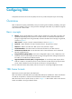
Configuring TRILL Transparent Interconnect of Lots of Links (TRILL) uses IS-IS to provide transparent Layer 2 forwarding. Overview TRILL combines the simplicity and flexibility of Layer 2 switching with the stability, scalability, and rapid convergence capability of Layer 3 routing. All these advantages make TRILL very suitable for large flat Layer 2 networks in data centers. Basic concepts • RBridge—Routing bridge (RB) that runs TRILL.
Figure 1 TRILL data frame format Table 1 describes the fields in the TRILL header. Table 1 TRILL header fields Field Description Ethertype The Ethertype is fixed to TRILL. V Version number, which is 0. When an RB receives a TRILL frame, it checks the V field and drops the frame if the V field is not 0. R Reserved for future extension. An ingress RB sets the R field to 0 when adding a TRILL header. Transit RBs and egress RBs ignore the field. Multi-destination attribute: M • 0—Known unicast frame.
How TRILL works TRILL establishes and maintains adjacencies between RBs by periodically advertising Hello frames, distributes LSPs among RB neighbors, and generates an LSDB for all RBs in the network. Based on the LSDB, each RB uses the SPF algorithm to calculate forwarding entries destined to other RBs. TRILL forwarding mechanisms Different types of frames are forwarded using different forwarding mechanisms. The following sections describe these mechanisms.
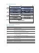
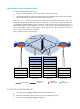
Multi-destination frame forwarding mechanism In a TRILL network, RBs do the following: • Compute a TRILL distribution tree for each VLAN according to the LSDB. • Use the TRILL distribution tree to guide the forwarding of multi-destination frames, which include multicast, broadcast, and unknown unicast frames in the VLAN. As shown in Figure 3, when a multicast frame from VLAN 10 enters the TRILL network, RB 1, which is an ingress RB, encapsulates the multicast frame into a TRILL frame.
• RFC 1195: Use of OSI IS-IS for Routing in TCP/IP and Dual Environments TRILL configuration task list When you configure TRILL, follow these guidelines: • Configuration in Layer 2 Ethernet interface view takes effect on only the current port. Configuration in Layer 2 aggregate interface view takes effect on the current interface and its member ports. Configuration on the member port of an aggregate interface takes effect after the member port leaves the aggregation group.
Enabling TRILL To enable TRILL on a port, first enable TRILL globally. Enable or disable TRILL on all ports in a VLAN, so that the ports in a VLAN have the same TRILL status (enabled or disabled). Do not enable both TRILL and EVB on a port. The allowed VLAN list of a TRILL-enabled port cannot overlap with that of an EVB-enabled port. For more information about EVB, see EVB Configuration Guide. When you set up a TRILL network, avoid the case that multiple TRILL neighbors are established for one RB port.
Step Command Remarks 2. Enable TRILL globally and enter TRILL view. trill By default, TRILL is disabled globally. 3. Return to system view. quit N/A 4. Enter Layer 2 Ethernet or aggregate interface view. interface interface-type interface-number N/A Enable TRILL on the port. trill enable By default, TRILL is disabled on a port. 5. Configuring the system ID and nickname for an RB The system ID and nickname of an RB are identifiers of the RB in the TRILL network.
To configure the link type of a TRILL port: Step Command Remarks 1. Enter system view. system-view N/A 2. Enter Layer 2 Ethernet or aggregate interface view. interface interface-type interface-number N/A Configure the link type of a TRILL port. trill link-type { access [ alone ] | hybrid | trunk } By default, the link type of a TRILL port is access without the alone attribute. 3. Configuring the DRB priority of a TRILL port On a broadcast network, TRILL must elect a DRB.
3. Enable automatic link cost calculation for TRILL ports. auto-cost enable By default, automatic link cost calculation is enabled for TRILL ports. 4. Return to system view. quit N/A 5. Enter Layer 2 Ethernet interface view or Layer 2 aggregate interface view. interface interface-type interface-number N/A Configure the link cost for a TRILL port. trill cost value The default setting is 2000. 6.
Configuring TRILL extension ports An egress RB cannot perform Layer 3 forwarding for de-encapsulated packets. As shown Figure 6, RB2 must connect to a gateway to communicate with a core device in another network. This method causes inconvenience and increases costs. Figure 6 Network diagram For the egress RB to operate as a gateway, you can configure two internal 40-GE ports as extension ports.
Step 2. 3. Command Remarks Configure an LSU1TGS48SF0 card to operate in port-extender mode (in standalone mode). switch-mode port-extender slot slot-number By default, the LSU1TGS48SF0 card operates in normal mode. Configure an LSU1TGS48SF0 card to operate in port-extender mode (in IRF mode). switch-mode port-extender chassis chassis-number slot slot-number By default, the LSU1TGS48SF0 card operates in normal mode.
Step Configure the CSNP interval. 6. Command Remarks trill timer csnp interval The default setting is 10 seconds. Adjusting LSP parameters You can modify the following LSP parameters: • LSP maximum age—An LSP originated by an RB uses the maximum age as the remaining lifetime. When the remaining lifetime of an LSP in the LSDB is 0 seconds, the RB removes the LSP's content, keeps the LSP's digest, and purges the LSP from the network by advertising the LSP that has the remaining lifetime set to 0.
Step Command Remarks The default setting is 1458 bytes. 5. Configure the maximum length of an LSP originated by an RB. lsp-length originate size The maximum length of an LSP originated by an RB cannot be greater than the maximum length of an LSP that can be received by an RB. Otherwise, the system displays error messages. The default setting is 1492 bytes. 6. Configure the maximum length of an LSP that can be received by an RB.
Set the SPF calculation interval for TRILL. 3. timer spf maximum-interval [ minimum-interval [ incremental-interval ] ] By default, the maximum SPF calculation interval is 10 seconds, the minimum SPF calculation interval is 10 milliseconds, and the SPF calculation incremental interval is 20 milliseconds. Configuring the TRILL unicast equal-cost routes Configuring multiple equal-cost routes to the same destination implements load balancing among these links and improves the link efficiency.
When N equal-cost links exist in the network, each TRILL distribution tree selects the link with the largest pseudo-node ID for forwarding packets. As shown in Figure 8, two equal-cost links exist between RB 1 and RB 3. Assume the link directly connecting RB 1 to RB 3 has the largest pseudo-node ID. Both the TRILL distribution tree rooted at RB 3 and the TRILL distribution tree rooted at RB 4 select the link.
To enable logging of TRILL neighbor changes: Step Command Remarks 1. Enter system view. system-view N/A 2. Enter TRILL view. trill N/A 3. Enable logging of TRILL neighbor changes. log-peer-change enable By default, logging of TRILL neighbor changes is enabled. Configuring SNMP for TRILL After you enable SNMP notification sending for TRILL, TRILL will generate notifications to notify NMS of important events on the local module and send the notifications to the SNMP module.
switchover occurs advertises the restart status to the neighbors, and allows the neighbors to re-establish connections. GR involves the following roles: • GR restarter—Graceful restarting router. It must be GR capable. • GR helper—A neighbor of the GR restarter. It helps the GR restarter to complete the GR process. To configure TRILL GR: Step Command Remarks 1. Enter system view. system-view N/A 2. Enter TRILL view. trill N/A 3. Enable GR for TRILL.
TRILL configuration example Network requirements As shown in Figure 9, configure TRILL in the Layer 2 data center network as follows: • Enable TRILL on the downlink ports of access layer devices to connect terminal devices to the TRILL network. • Enable TRILL on the uplink ports of access layer devices, and configure these uplink ports as trunk ports to pass TRILL frames to the TRILL network.
[RB1-trill] quit [RB1] interface ten-gigabitethernet 1/0/1 [RB1-Ten-GigabitEthernet1/0/1] trill enable [RB1-Ten-GigabitEthernet1/0/1] quit # Configure RB 2 through RB 5 in the same way RB 1 is configured. 2. Configure the uplink port of access layer devices: # Enable TRILL on uplink port Ten-GigabitEthernet 1/0/2 through Ten-GigabitEthernet 1/0/5 of RB 1, and configure these ports as trunk ports.
[RB6] interface ten-gigabitethernet 1/0/5 [RB6-Ten-GigabitEthernet1/0/5] trill enable [RB6-Ten-GigabitEthernet1/0/5] trill link-type trunk [RB6-Ten-GigabitEthernet1/0/5] quit # Configure RB 7 through RB 9 in the same way RB 6 is configured. 4. Configure the uplink ports of the distribution layer devices: # Enable TRILL on uplink ports Ten-GigabitEthernet 1/0/6 and Ten-GigabitEthernet 1/0/7 of RB 6.
[RB1] display trill unicast-route Destination Interface NextHop ----------------------------------------------0x5801 N/A N/A 0x5802 XGE1/0/2 0x5806 XGE1/0/3 0x5807 XGE1/0/4 0x5808 XGE1/0/5 0x5809 XGE1/0/2 0x5806 XGE1/0/3 0x5807 XGE1/0/4 0x5808 XGE1/0/5 0x5809 XGE1/0/2 0x5806 XGE1/0/3 0x5808 XGE1/0/4 0x5808 XGE1/0/5 0x5809 XGE1/0/2 0x5806 XGE1/0/3 0x5807 XGE1/0/4 0x5808 XGE1/0/5 0x5809 0x5806 XGE1/0/2 Direct 0x5807 XGE1/0/3 Direct 0x5808 XGE1/0/4 Direct 0x5809
TRILL extension port configuration example Network requirements As shown in Figure 10, RB1 and RB2 are in a TRILL network. RB1 is connected to a server, and RB2 is connected to a core device in a routed network. RB2 has an LSU1TGS48SF0 card in slot 3. RB2 performs TRILL encapsulation and decapsulation, and serves as a gateway to perform Layer 3 forwarding between the TRILL network and the routed network.
[RB1-Ten-GigabitEthernet5/0/5] trill enable [RB1-Ten-GigabitEthernet5/0/5] trill link-type trunk [RB1-Ten-GigabitEthernet5/0/5] quit # Assign port Ten-GigabitEthernet 5/0/11 to VLAN 100. [RB1] interface ten-gigabitethernet 5/0/11 [RB1-Ten-GigabitEthernet5/0/11] port access vlan 100 # Enable TRILL on port Ten-GigabitEthernet 5/0/11, and use the default TRILL link type access. [RB1-Ten-GigabitEthernet5/0/11] trill enable [RB1-Ten-GigabitEthernet5/0/11] quit 2. Configure RB2: # Enable TRILL.
[RB2-FortyGigE3/0/50] undo stp enable [RB2-FortyGigE3/0/50] quit # Assign IP address 30.1.1.1/24 to VLAN-interface 101. [RB2] interface Vlan-interface 101 [RB2-Vlan-interface101] ip address 30.1.1.1 255.255.255.0 [RB2-Vlan-interface101] quit # Assign port Ten-GigabitEthernet 3/0/48 to VLAN 102. [RB2] vlan 102 [RB2-vlan102] quit [RB2-vlan102] interface ten-gigabitethernet 3/0/48 [RB2-Ten-GigabitEthernet3/0/48] port access vlan 102 [RB2-Ten-GigabitEthernet3/0/48] quit # Assign IP address 20.1.1.
reak 56 bytes from 30.1.1.1: icmp_seq=0 ttl=255 time=1.352 ms 56 bytes from 30.1.1.1: icmp_seq=1 ttl=255 time=2.938 ms 56 bytes from 30.1.1.1: icmp_seq=2 ttl=255 time=1.339 ms 56 bytes from 30.1.1.1: icmp_seq=3 ttl=255 time=1.154 ms 56 bytes from 30.1.1.1: icmp_seq=4 ttl=255 time=2.004 ms --- Ping statistics for 30.1.1.1 --5 packet(s) transmitted, 5 packet(s) received, 0.0% packet loss round-trip min/avg/max/std-dev = 1.154/1.757/2.938/0.
Support and other resources Contacting HP For worldwide technical support information, see the HP support website: http://www.hp.
Conventions This section describes the conventions used in this documentation set. Command conventions Convention Description Boldface Bold text represents commands and keywords that you enter literally as shown. Italic Italic text represents arguments that you replace with actual values. [] Square brackets enclose syntax choices (keywords or arguments) that are optional. { x | y | ... } Braces enclose a set of required syntax choices separated by vertical bars, from which you select one.
Network topology icons Represents a generic network device, such as a router, switch, or firewall. Represents a routing-capable device, such as a router or Layer 3 switch. Represents a generic switch, such as a Layer 2 or Layer 3 switch, or a router that supports Layer 2 forwarding and other Layer 2 features. Represents an access controller, a unified wired-WLAN module, or the switching engine on a unified wired-WLAN switch. Represents an access point.
Index TRILL, 17 A access TRILL access port link, 7 adjusting distributing TRILL distribution tree, 14 DRB TRILL port priority, 8 TRILL LSP parameters, 12 TRILL SPF algorithm parameters, 13 algorithm TRILL SPF algorithm parameter adjustment, 13 E enabling TRILL, 6 appointed VLAN-x forwarder.
TRILL RB system ID, 7 I TRILL routing bridge network, 1 ID TRILL SNMP configuration, 16 TRILL RB system ID, 7 TRILL SPF algorithm parameter adjustment, 13 inhibition time (TRILL), 11 IS-IS TRILL configuration, 1, 5, 18 TRILL timer configuration, 11 network management TRILL basic concepts, 1 L Layer 2 TRILL configuration, 1, 5, 18 link TRILL configuration, 1, 5, 18 TRILL link cost configuration, 8 TRILL link state database, 1 TRILL configuration, 1, 5, 18 nickname (TRILL), 1 NMS TRILL SNMP configur
enabling TRILL neighbor change logging, 15 frame forwarding (multi-destination), 4 maintaining TRILL, 17 frame forwarding (unicast), 3 protocols and standards GR configuration, 16 how it works, 3 TRILL, 4 LSP parameter adjustment, 12 R maintaining, 17 RB neighbor change logging, 15 TRILL extension port configuration, 10, 22 port DRB priority configuration, 8 TRILL nickname, 7 port link cost configuration, 8 TRILL system ID, 7 port link type configuration, 7 restrictions protocols and stan