HP FlexFabric 11900 Switch Series FCoE Configuration Guide Part number: 5998-4069 Software version: Release 2105 and later Document version: 6W100-20130515
Legal and notice information © Copyright 2013 Hewlett-Packard Development Company, L.P. No part of this documentation may be reproduced or transmitted in any form or by any means without prior written consent of Hewlett-Packard Development Company, L.P. The information contained herein is subject to change without notice.
Contents FCoE overview ····························································································································································· 1 Storage area network ······················································································································································· 1 FC SAN ···················································································································································
Configuring the fabric timers ········································································································································ 25 Configuring the fabric timers in system view······································································································ 25 Configuring the fabric timers in VSAN view ······································································································ 26 Configuring the fabric reconfiguration ····
FSPF configuration example·········································································································································· 55 Network requirements ··········································································································································· 55 Configuration procedure ······································································································································ 55 Verifying the conf
Configuring FC tracert ··············································································································································· 83 Overview········································································································································································· 83 Configuration procedure ·········································································································································
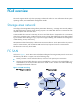
FCoE overview The switch supports FCoE only when operating in advanced mode. For more information about system operating modes, see Fundamentals Configuration Guide. Storage area network According to the Storage Networking Industry Association dictionary, "a storage area network (SAN) is any high-performance network whose primary purpose is to enable disk devices to communicate with computer systems and with each other." A SAN enables the universal connectivity of servers and disk devices.
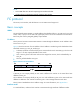
NOTE: • An FC SAN refers to a network comprising FCF switches and nodes. • A fabric refers to a transmission network comprising FCF switches. FC protocol The servers, FCF switches, and disk devices in an FC SAN must all support FC. Basic concepts WWN The World Wide Name (WWN) is a 64-bit address that identifies a fabric or an entity (such as an FCF switch, node, or port) in an FC SAN. The upper-layer protocol of FC uses WWNs for communication. Each entity has a factory-assigned globally unique WWN.
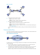
Figure 3 Port modes • • A node has the following interface modes: { N_Port—Directly connects to a fabric. { NL_Port—Connects to a fabric through an arbitrated loop. An FCF switch provides the following port modes: { F_Port—Connects to an N_Port or an NP_Port on another FCF switch. { E_Port—Connects to an E_Port on another FCF switch. { NP_Port—Connects to an F_Port on another FCF switch. For more information about NP_Port, see "Configuring NPV.
3. To access a disk device, the server needs to send a name service query request to its directly-connected FCF switch to obtain the list of disk devices in the fabric and their WWNs and FC addresses. 4. After the server obtains the FC address of the disk device, the server can send FC frames (with the FC address of the disk device as the destination FC address) to the FCF switch nearby. 5.
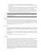
Figure 5 FCoE for I/O consolidation As shown in Figure 5, in the traditional network, the server is connected to the LAN through an Ethernet interface and to the SAN through an FC interface. In the FCoE network, the server is connected to the FCoE-capable FCF switch, and then the FCF switch is connected to the LAN through an Ethernet interface and to the SAN through an FC interface. The links between the server and the FCF switch and between FCF switches can transmit both Ethernet frames and FC frames.
VFC interfaces support E mode, F mode (default), and NP mode. The virtual node (VN) interface is a logical interface on an ENode to simulate the function of a physical FC interface. FIP protocol FCoE initialization protocol (FIP) is an FCoE control protocol that establishes and maintains virtual links.
Procedure for receiving and sending FC frames over Ethernet An FC frame is transmitted over Ethernet using the following workflow: • FIP establishes a virtual link between the VFC interface of the FCF switch and the VN interface of the ENode or between VFC interfaces of two FCF switches. • After the virtual link is established, the FCF switch encapsulates the FC frame in an FCoE frame and sends it out.
field carries the FCF priority of the VFC interface. If they do not match, it discards the Discovery Solicitation. 3. The FCF switch periodically sends unsolicited Discovery Advertisements, whose fcf priority field carries the FCF priority of the system. The sending interval is specified by using the fcoe fka-adv-period command and defaults to 8 seconds. 4.
Figure 10 FCF network diagram In an FCoE environment as shown in Figure 10, different from a pure FC network, the ENode and FCF switch communicate over Ethernet interfaces on a lossless Ethernet network. The FCoE virtual link between the ENode and FCF switch connects a VN interface to a VFC interface, and the FCoE virtual link between FCF switches connects two VFC interfaces. Each FCF switch is assigned a domain ID.
• FC-SW-5, Fibre Channel - Switch Fabric - 5 • FC-LS-2, Fibre Channel - Link Services - 2 • FC-GS-6, Fibre Channel - Generic Services - 6 • FC-BB-5, Fibre Channel - Back Bone – 5 10
Configuring an FCoE mode The switch supports FCoE only when operating in advanced mode. For more information about system operating modes, see Fundamentals Configuration Guide. FCoE features supported in different FCoE modes The switch supports two FCoE modes: FCF mode and NPV mode. Each mode has different features as shown in Table 1. You can choose to configure different features based on the FCoE mode of a switch.
Configuring VFC interfaces and FIP VFC interfaces and FIP configuration task list Tasks at a glance (Required.) Configuring a VFC interface (Required.) Enabling FCoE for a VLAN and mapping a VSAN to the VLAN (Optional.) Configuring the FC-MAP value (Optional.) Configuring the FKA advertisement period value (Optional.) Configuring the FCF priority Configuring a VFC interface Step Command Remarks 1. Enter system view. system-view N/A 2. Create a VFC interface and enter its view.
Enabling FCoE for a VLAN and mapping a VSAN to the VLAN When you use a VFC interface to transmit packets, the Ethernet interface bound to the VFC interface can allow multiple VLANs. You should enable FCoE for a VLAN and map a VSAN to the VLAN, so that the packets from the VSAN are tagged with the VLAN tag and transmitted within the VLAN. Configuration restrictions and guidelines Follow these restrictions and guidelines when you configure this feature: • FCoE cannot be enabled for VLAN 1.
Step 2. Configure an FC-MAP value. Command Remarks fcoe fcmap fc-map The default setting is 0x0EFC00. Configuring the FKA advertisement period value FKA advertisement period determines the length of time it takes the switch to detect the disconnection of a virtual link can be detected. • After setting up a virtual link with a peer switch, a switch sends unsolicited Discovery Advertisements every FKA advertisement period on its VFC interfaces in E mode to maintain the established virtual link.
Recommended value 60–90 seconds 300–600 seconds Application scenarios Remarks Active/standby switchover on the switch takes more than 2.5 x 60 seconds because of the amount of FCoE configuration. ISSU reboot on a dual-MPU switch takes more than 2.5 x 60 seconds because of the amount of FCoE configuration. ISSU reboot on a single-MPU switch and connecting to no nodes. For more information about ISSU, see Fundamentals Configuration Guide.
Step Command Remarks 1. Enter system view. system-view N/A 2. Enter VFC interface view. interface vfc interface-number N/A 3. Configure the FCF priority for the VFC interface. fcoe fcf-priority priority The default setting is 128. The configuration takes effect on a VFC interface only when it operates in F mode. Displaying and maintaining VFC interfaces and FIP Execute display commands in any view. Task Command Display VFC interface information.
Configuration procedure This section describes the configurations for VFC interfaces and FIP on the FCF switch. 1. Configure Switch A: # Configure Switch A to operate in advanced mode, save the configuration, and reboot Switch A. (Skip this step if the switch is operating in advanced mode.
[SwitchB] system-working-mode advance Do you want to change the system working mode? [Y/N]:y The system working mode is changed, please save the configuration and reboot the system to make it effective. # Create VSAN 10 and configure Switch B to operate in FCF mode. system-view [SwitchB] fcoe-mode fcf [SwitchB] vsan 10 [SwitchB-vsan10] quit # Create interface VFC 1, configure it to operate in E mode, bind it to interface Ten-GigabitEthernet 1/0/2, and assign it to VSAN 10 as a trunk port.
Setting up a fabric Overview A fabric transmits data for servers and disk devices. When setting up a fabric, you must assign a domain ID to each FCF switch in the fabric and assign an FC address to each node connected to the fabric. You can build a fabric through one of the following modes: • Static mode—You must manually assign domain IDs to all switches in the network, and then each switch assigns FC addresses to the N_Ports connected to it.
replaces the locally-record principal switch information with the principal switch information recorded in the packet, and notifies the other switches. Finally, all switches in the network make an agreement on which switch is the principal switch. 3. When the PSST times out, if the locally-recorded principal switch information is the local switch, the switch becomes the principal switch. After the principal switch is selected, the WWN of the principal switch becomes the fabric name.
downstream switch that no domain ID can be assigned, the downstream switch isolates its upstream principal link and brings down the relevant interface. For more information about domain ID types, see "Configuring a domain ID for a switch." { 5. Otherwise, the downstream accepts the domain ID assigned by the principal switch and notifies the nearby downstream switch to request a domain ID from the principal switch. Repeat steps 2 through 4 until all downstream switches have been assigned domain IDs.
Tasks at a glance Remarks (Optional.) Configuring the fabric timers N/A Building a fabric dynamically Tasks at a glance Remarks (Required.) Configuring a VFC interface N/A (Required.) Enabling or disabling the fabric configuration function To dynamically build a fabric, you must enable the fabric configuration function. (Optional.) Setting the switch priority Principal switch selection relies on the switch priority. (Optional.) Configuring the allowed domain ID list N/A (Optional.
Setting a fabric name The fabric name configured takes effect only on a statically-built fabric. You must configure the same fabric name for all switches in a VSAN. To set a fabric name: Step Command Remarks 1. Enter system view. system-view N/A 2. Enter VSAN view. vsan vsan-id N/A 3. Configure a fabric name. By default, the fabric name is null. If the user does not configure a fabric name, the switch WWN is used as the fabric name after FCoE is enabled.
Configuring the allowed domain ID list Configuring the allowed domain ID list has an effect on switches as follows: • Principal switch—Can only assign domains IDs within the allowed domain ID list. If the allowed domain ID list configured does not include any of the already assigned domain IDs or manually configured domain IDs, the configuration will fail. • Non-principal switch—The manually configured domain ID must be within the allowed domain ID list. Otherwise, the configuration will fail.
Step Configure a domain ID for the switch. 3. Command Remarks domain-id domain-id { preferred | static } By default, the domain ID of a switch is 0 and is of the preferred type. Configuring the mapping between the N_Port WWN and the FC address If you bind the WWN of an N_Port to an FC address, when the N_Port requests an FC address, the switch assigns the bound FC address to it. The WWN of an N_Port can be bound to only one FC address, and vice versa.
Step Command Remarks 3. Configure the global error detection timeout period. fc timer error-detect value By default, the error detection timeout period is 2000 milliseconds. 4. Configure the global resource allocation timeout period. fc timer resource-allocation value By default, the resource allocation timeout period is 10000 milliseconds. Configuring the fabric timers in VSAN view Step Command Remarks 1. Enter system view. system-view N/A 2. Enter VSAN view. vsan vsan-id N/A 3.
{ { The system automatically performs a non-disruptive reconfiguration if the principal switch information of the two fabrics is different and the domain ID lists are not empty or overlapping. You can manually initiate a disruptive reconfiguration to trigger the fabric reconfiguration if ports are isolated and priority values of switches are modified. When the principal switch in a fabric is down, the system automatically performs a non-disruptive reconfiguration.
Task Command Display the domain information of the specified VSAN. display fc domain [ vsan vsan-id ] Display the list of domain IDs dynamically allocated in the specified VSAN. display fc domain-list [ vsan vsan-id ] Display fabric timers. display fc timer [ distributed-services | error-detect | resource allocation ] [ vsan vsan-id ] Display node login information. display fc login [ vsan vsan-id ] [ count ] Display the SCR table for an N_Port.
Non-disruptive reconfiguration or isolating the switch may be performed. Continu e? [Y/N]:y [SwitchA-vsan1] quit # Create interface VFC 200, configure it to operate in E mode, bind it to interface Ten-GigabitEthernet 1/0/1, and assign it to VSAN 1 as a trunk port. [SwitchA] interface vfc 200 [SwitchA-Vfc200] fc mode e [SwitchA-Vfc200] bind interface ten-gigabitethernet1/0/1 [SwitchA-Vfc200] port trunk vsan 1 [SwitchA-Vfc200] quit # Configure interface Ten-GigabitEthernet 1/0/1 to allow VLAN 20.
# Configure a name for the fabric. [SwitchA-vsan1] fabric-name 11:11:11:11:11:11:11:11 # Configure the domain ID as 2. [SwitchB-vsan1] domain-id 2 static Non-disruptive reconfiguration or isolating the switch may be performed. Continu e? [Y/N]:y [SwitchB-vsan1] quit # Create interface VFC 200, configure it to operate in E mode, bind it to interface Ten-GigabitEthernet 1/0/1, and assign it to VSAN 1 as a trunk port.
Switch WWN: 48:33:43:2d:46:43:1A:1A Fabric name: 11:11:11:11:11:11:11:11 Priority: 128 Domain ID: 1 Configuration information: Domain configure: Disabled Domain auto-reconfigure: Disabled Fabric name: 11:11:11:11:11:11:11:11 Priority: 128 Domain ID: 1 (static) Principal switch running time information: Priority: 128 No interfaces available. The output shows that the domain configuration is complete and that the runtime domain ID of Switch A is 1. 2. Verify the configurations on Switch B.
Figure 15 Network diagram Configuration procedure 1. Configure Switch A: # Configure Switch A to operate in advanced mode, save the configuration, and reboot Switch A. (Skip this step if the switch is operating in advanced mode.) system-view [SwitchA] system-working-mode advance Do you want to change the system working mode? [Y/N]:y The system working mode is changed, please save the configuration and reboot the system to make it effective.
[SwitchA-Vfc1] bind interface ten-gigabitethernet4/0/1 [SwitchA-Vfc1] fc mode e [SwitchA-Vfc1] port trunk vsan 1 [SwitchA-Vfc1] quit 2. Configure Switch B: # Configure Switch B to operate in advanced mode, save the configuration, and reboot Switch B. (Skip this step if the switch is operating in advanced mode.
# Configure Switch C to operate in advanced mode, save the configuration, and reboot Switch C. (Skip this step if the switch is operating in advanced mode.) system-view [SwitchC] system-working-mode advance Do you want to change the system working mode? [Y/N]:y The system working mode is changed, please save the configuration and reboot the system to make it effective.
[SwitchD] system-working-mode advance Do you want to change the system working mode? [Y/N]:y The system working mode is changed, please save the configuration and reboot the system to make it effective. # Enable the fabric configuration function (optional, because this function is enabled by default), and configure Switch D to operate in FCF mode. system-view [SwitchD] fcoe-mode fcf [SwitchD] vsan 1 [SwitchD-vsan1] domain configure enable # Configure the domain ID as 14.
Domain configure: Enabled Domain auto-reconfigure: Disabled Fabric name: 48:33:43:2d:46:43:1A:1A Priority: 128 Domain ID: 11 (preferred) Principal switch running time information: Priority: 1 Path Interface Upstream Vfc 1 Downstream Vfc 2 The output shows that the domain configuration is complete and that the principal switch assigns domain ID 11 to Switch A. # Display the domain ID list of VSAN 1.
Configuring VSAN Overview The virtual storage area network (VSAN) technology breaks a physical SAN into multiple VSANs, and provides more secure, reliable, and flexible services. Devices in a VSAN cannot get information about any other VSAN and devices in any other VSAN. Each VSAN performs the following operations independently: selecting a principal switch, assigning domain IDs, running routing protocols, maintaining routing table and FIB table, and providing services.
Figure 16 Trunk VSAN network VSAN 1 VSAN 1 N_Port N_Port Disk A Server A FC Fabric F_Port F_Port Server B F_Port E_Port E_Port F_Port FC switch B FC switch A Disk B N_Port N_Port VSAN 2 VSAN 2 During the transmission process, VFT_Headers are added to and removed from the frames. A switch can use the same physical interface to support multiple VSANs. The trunk VSAN technology reduces the number of physical connections, actually implementing logical isolation in a physical network.
Step Command Remarks 1. Enter system view. system-view N/A 2. Enter VFC interface view. interface vfc interface-number N/A 3. Assign the VFC interface to the specified VSANs as a trunk port so that the interface allows the specified VSANs to pass through. By default, a VFC interface does not belong to any VSAN as a trunk port. port trunk vsan vsan-id-list When you assign a VFC interface to a VSAN as a trunk port, the VSAN may not exist.
• Configure the two interfaces connecting FCF switch Switch A to the servers to operate in F mode, and assign the two interfaces as trunk ports to VSAN 10 and VSAN 20, respectively. • Configure the three interfaces connecting FCF switch Switch B to the disk devices to operate in F mode, and assign the three interfaces as trunk ports to VSAN 10 or VSAN 20.
# Create interface VFC 100 (uplink interface), bind it to interface Ten-GigabitEthernet 1/0/3, configure it to operate in E mode, and assign it to VSANs 10 and 20 as a trunk port. [SwitchA] interface Vfc 100 [SwitchA-Vfc102] bind interface Ten-GigabitEthernet1/0/3 [SwitchA-Vfc100] fc mode e [SwitchA-Vfc100] port trunk vsan 10 20 2. Configure Switch B in the same way Switch A is configured. (Details not shown.) Verifying the configurations 1.
Configuring FC routing and forwarding Overview Routing and forwarding in an FC SAN is achieved through FCF switches. When an FCF switch receives a packet, an FCF switch selects an optimal route based on the destination address and forwards the packet to the next FCF switch in the path until the packet reaches the last FCF switch, which forwards the packet to the destination node. Routing provides the path information that guides the forwarding of packets.
• Protocol—Protocol type, which can be DIRECT (direct routes), STATIC (static routes), or FSPF (FSPF routes). • Preference—There might be direct routes, static routes, and FSPF routes to the same destination. All of these types of routes are assigned preferences. Direct routes have a preference of 0, static routes have a preference of 10, and FSPF routes have a preference of 20. The optimal route is the one with the highest priority (smallest preference value). • Cost—Cost of the route.
However, the static routes cannot automatically adapt to network topology changes. When the network fails or the network topology changes, the routes might fail to be reachable, and the network is interrupted. In this case, you must manually modify the static routes. Static routes support equal-cost routes. When you configure multiple equal-cost static routes to the same destination but with different outgoing interfaces, equal-cost routes are generated.
After receiving an LSU, a switch needs to acknowledge its LSR with an LSA. Otherwise, the neighboring switch retransmits the LSR. How FSPF works FSPF works as follows: 1. The switch periodically sends hello packets to establish neighbor relationships with other switches. 2. After establishing neighbor relationships, the switches synchronize LSDBs by exchanging all LSRs in their respective LSDBs. A switch carries LSRs in LSUs and acknowledges received LSRs with LSAs. 3.
FSPF configuration task list Tasks at a glance Change FSPF parameters for a VSAN in VSAN view: • • • • (Required.) Enabling FSPF (Optional.) Configuring the shortest SPF calculation interval (Optional.) Configuring the minimum LSR receiving interval (Optional.) Configuring the minimum LSR refresh interval (Optional.
Step 3. Configure the shortest SPF calculation interval. Command Remarks fspf spf-hold-time value The default setting is 0 second. Configuring the minimum LSR receiving interval The minimum LSR receiving interval specifies the time between receiving LSRs in a VSAN. Any LSR instances of the same LSR received within this time are dropped. This helps avoid frequent SPF calculations caused by LSDB updating. To configure the minimum LSR receiving interval: Step Command Remarks 1. Enter system view.
Configuring the hello interval for an interface The hello interval specifies the time between the hello packets sent periodically by the switch to discover and maintain neighbor relationships. NOTE: The configured hello interval must be smaller than the dead interval and must be the same at the two ends of the link. To configure the interface hello interval: Step Command Remarks 1. Enter system view. system-view N/A 2. Enter VFC interface view. interface vfc interface-number N/A 3.
Step Command Remarks 2. Enter VFC interface view. interface vfc interface-number N/A 3. Configure the LSR retransmission interval for the VFC interface in a specified VSAN. fspf retransmit-interval value vsan vsan-id The default setting is 5 seconds. Disabling FSPF for an interface With FSPF enabled, an interface can participate in SPF calculation. To avoid SPF calculations on an interface, disable FSPF on the interface. To disable FSPF on an interface: Step Command Remarks 1.
Displaying and maintaining FC routing and forwarding Execute display commands in any view. Task Display FC routing table information. Display FC FIB table information. Display FC Exchange table information (in standalone mode). Display FC Exchange table information (in IRF mode).
Figure 18 Network diagram Switch B Domain ID: 2 VFC200 XGE1/0/2 VFC201 XGE1/0/3 VFC100 XGE1/0/1 VFC300 XGE1/0/3 Switch A Domain ID: 1 Switch C Domain ID: 3 Configuration procedure 1. Configure Switch A: # Configure Switch A to operate in advanced mode, save the configuration, and reboot Switch A. (Skip this step if the switch is operating in advanced mode.
# Enable FCoE for VLAN 10 and bind VLAN 10 to VSAN 1. [SwitchA] vlan 10 [SwitchA-vlan10] fcoe enable vsan 1 [SwitchA-vlan10] quit # Configure two static routes. [SwitchA-vsan1] fc route-static 020000 8 Vfc100 [SwitchA-vsan1] fc route-static 030000 8 Vfc100 2. Configure Switch B: # Configure Switch B to operate in advanced mode, save the configuration, and reboot Switch B. (Skip this step if the switch is operating in advanced mode.
# Enable FCoE for VLAN 10 and bind VLAN 10 to VSAN 1. [SwitchB] vlan 10 [SwitchB-vlan10] fcoe enable vsan 1 [SwitchB-vlan10] quit # Configure two static routes. [SwitchB-vsan1] fc route-static 010000 8 Vfc200 [SwitchB-vsan1] fc route-static 030000 8 Vfc201 3. Configure Switch C: # Configure Switch C to operate in advanced mode, save the configuration, and reboot Switch C. (Skip this step if the switch is operating in advanced mode.
Verifying the configurations # Display the FC routing table in VSAN 1 on Switch A. [SwitchA-vsan1] display fc routing-table vsan 1 Routing Table: VSAN 1 Destinations : 6 Routes : 6 Destination/mask Protocol Preference Cost Interface 0x020000/8 STATIC 10 0 Vfc100 0x030000/8 STATIC 10 0 Vfc100 0xfffc01/24 DIRECT 0 0 InLoop0 0xfffffa/24 DIRECT 0 0 InLoop0 0xfffffc/24 DIRECT 0 0 InLoop0 0xfffffd/24 DIRECT 0 0 InLoop0 # Display the FC routing table in VSAN 1 on Switch B.
0.00% packet loss round-trip min/avg/max = 9/18/25 ms The output shows that Switch A can reach Switch C. FSPF configuration example Network requirements As shown in Figure 19, configure FSPF to enable the two FCF switches to communicate with each other. Figure 19 Network diagram Configuration procedure 1. Configure Switch A: # Configure Switch A to operate in advanced mode, save the configuration, and reboot Switch A. (Skip this step if the switch is operating in advanced mode.
[SwitchA-vsan2] quit # Enable FCoE for VLAN 10 and bind VLAN 10 to VSAN 2. [SwitchA] vlan 10 [SwitchA-vlan10] fcoe enable vsan 2 [SwitchA-vlan10] quit # Enable FSPF globally. [SwitchA-vsan2] fspf enable [SwitchA-vsan2] quit # Enable FSPF for interface VFC 100. [SwitchA] interface Vfc 100 [SwitchA-Vfc100] port trunk vsan 2 [SwitchA-Vfc100] undo fspf silent vsan 2 2. Configure Switch B: # Configure Switch B to operate in advanced mode, save the configuration, and reboot Switch B.
# Enable FSPF globally. [SwitchB-vsan2] fspf enable [SwitchB-vsan2] quit # Enable FSPF for interface VFC 100. [SwitchB] interface Vfc 100 [SwitchB-Vfc 100] port trunk vsan 2 [SwitchB-Vfc 100] undo fspf silent vsan 2 Verifying the configurations # Display FSPF neighbor information on Switch A.
Configuring FC zones Overview The VSAN technology divides a physical SAN into multiple VSANs, which are separated from one another, and provides more secure, reliable, and flexible services. A VSAN, however, cannot perform access control over the servers and disk devices (or the N_Ports) connected to a fabric. N_Ports in the same VSAN can access one another only if these N_Ports register name services. This creates data security risks.
• Each VSAN can have multiple zone sets, each zone set can have multiple zones, and each zone can have multiple zone members. • To facilitate configuration, zone membership configuration supports use of zone aliases. A zone alias is a set of N_Ports, which can be considered as a whole. You can add common zone members in multiple zones to a zone alias, and call the zone alias in different zones to simplify configuration.
Default zone The N_Ports in zones of the active zone set are part of the active zone set. Registered N_Ports that are not in the active zone set automatically become part of the default zone. If members of the default zone are allowed to access each other, the default zone can be considered to be part of the active zone set, and it participates in access control among N_Ports. Otherwise, the default zone is not in the active zone set and does not participate in access control among the N_Ports.
Figure 22 Distribution process The distribution process is as follows: 1. The manager switch obtains the status of each managed switch through an ACA request, which carries the fabric-wide list of domain IDs (addresses of all switches in the fabric) known to the manager switch. After sending the ACA request, the manager switch enters the locked state. After receiving the ACA request, a managed switch compares its list of domain IDs with that in the packet.
7. After receiving the RCA request, the managed switch releases its change authorization state and replies with an ACC packet. 8. The manager switch releases its change authorization state after receiving ACC packets from all managed switches. NOTE: • [1] This actually requires the routing information across the fabric to be correct and consistent and eliminating unreachable routes. You need to pay special attention to this in the case of using static routes.
Figure 23 Zone merge process between two switches The zone merge process is as follows: 1. Switch A and Switch B are new neighbors to each other. Suppose that Switch A first initiates a merge to Switch B: a. Switch A sends an MRRA request carrying the size of its data to be merged to Switch B. b. After receiving the MRRA request, Switch B determines whether to accept the merge according to its local data size. If the size of the data to be merged is acceptable, it replies with an ACC packet.
NOTE: Consistent active zone sets among switches can be achieved by a merge. Consistent zone databases achieved after a merge, however, require all participating switches to be configured with complete merge. Zone merge rules Table 4 Zone merge rules Local database Neighbor database Merge status Merge result Successful The union of the local database and neighbor database. Zone sets with the same name are merged. Successful The union of the local database and neighbor database.
Tasks at a glance (Required.) Configuring zone distribution and merge types (Required.) Activating a zone set and distributing it to the entire fabric (Optional.) Triggering a complete distribution (Optional.) Renaming zone aliases, zones, and zone sets (Optional.) Copying zone aliases, zones, and zone sets (Optional.) Deleting the zone database NOTE: • You cannot modify zone configurations during zone distribution or merge. • In a fabric, only one manager switch can initiate distribution at a time.
Step 4. Add a member to the zone. Command Remarks member { fcid fcid | pwwn pwwn | zone-alias zone-alias-name } By default, no member exists in a zone. Configuring zone sets You can configure a maximum of 128 zone sets for all VSANs on a switch. To configure a zone set: Step Command Remarks 1. Enter system view. system-view N/A 2. Enter VSAN view. vsan vsan-id N/A 3. Create a zone set and enter its view. zoneset name zoneset-name If the zone set has been created, enter its view directly.
Step 3. Configure zone distribution and merge types as complete distribution and complete merge. Command Remarks zoneset distribute full The default setting is incomplete distribution and incomplete merge. Activating a zone set and distributing it to the entire fabric You can activate a zone set as the active zone set on a switch, distribute the active zone set to the entire fabric, and implement access control through the active zone set.
Step Command 1. Enter system view. system-view 2. Enter VSAN view. vsan vsan-id 3. Activate a complete distribution. zoneset distribute Renaming zone aliases, zones, and zone sets Step Command Remarks 1. Enter system view. system-view N/A 2. Enter VSAN view. vsan vsan-id N/A 3. Rename a zone alias. zone-alias rename old-name new-name The zone alias to be renamed must have been created, and the new zone alias must not have been created. 4. Rename a zone.
Deleting the zone database You can delete the zone database for the specified VSAN, including all zone sets, zones, and zone aliases, but not the active zone set. To delete the zone database: Step Command 1. Enter system view. system-view 2. Enter VSAN view. vsan vsan-id 3. Delete the zone database. delete zone database all Displaying and maintaining FC zones Execute display commands in any view. Task Command Display zone alias information.
Figure 24 Network diagram Configuration considerations To meet the preceding requirements, divide VSAN 1 into three zones as follows: • Zone 1 consists of Server A. • Zone 2 consists of Server B and Disks A, B, and C. • Zone 3 consists of Server C and Disks B and C. Configure Switch A and distribute the full zone database to Switch B: • Create zone alias Alias 1, which consists of Disks B and C, to simplify the configuration.
[SwitchA-vsan1] zone-alias name Alias1 [SwitchA-vsan1-zone-alias-Alias1] member pwwn 22:33:44:55:66:77:88:99 [SwitchA-vsan1-zone-alias-Alias1] member fcid 020004 [SwitchA-vsan1-zone-alias-Alias1] quit # Create a zone Zone1 and specify FC ID 010001 as its member. Create a zone Zone2 and specify the FC ID 010002 and pWWN 11:22:33:44:55:66:77:88, whose zone aliases are Alias1, as its members. Create Zone 3 and specify FC ID 010003, whose zone alias is Alias1, as its member.
zone-alias Alias1 fcid 0x020004 pwwn 22:33:44:55:66:77:88:99 # Display information about Zone 2 in VSAN 1. display zone name Zone2 vsan 1 VSAN 1: zone name Zone2 fcid 0x010002 pwwn 11:22:33:44:55:66:77:88 zone-alias Alias1 fcid 0x020004 pwwn 22:33:44:55:66:77:88:99 # Display the zone or zone alias to which 020004 (FC ID type) belongs. display zone member fcid 020004 fcid 0x020004 VSAN 1: zone-alias Alias1 zone Zone2 zone Zone3 # Display information about the active zone set in VSAN 1.
Configuring NPV Overview NPV enables an FC SAN to accommodate more than 239 switches. NPV switches forward traffic from nodes to the core switch. Figure 25 shows a typical NPV network diagram. Figure 25 NPV network diagram NOTE: An NPV switch must be directly connected to the core switch. Downlink interface and downlink A downlink interface, also known as a server interface, is an interface through which an NPV switch connects to a node.
Downlink-to-uplink interface mappings NPV switches automatically map downlink interfaces to uplink interfaces. Before a downlink interface is brought up, the NPV switch maps it to the uplink interface with the minimum load among all operational uplink interfaces. The load here indicates the number of downlink interfaces mapped to the uplink interface.
To configure an uplink interface: Step Command Remarks 1. Enter system view. system-view N/A 2. Enter VFC interface view. interface vfc interface-number This interface is connected to the core switch. 3. Configure the VFC interface to operate in NP mode. fc mode np By default, a VFC interface on an NPV switch operates in F mode. Configuring downlink interfaces Downlink interfaces must be VFC interfaces in F mode. To configure a downlink interface: Step Command Remarks 1.
Step 3. Configure a downlink-to-uplink interface mapping. Command Remarks npv traffic-map server-interface interface-type interface-number external-interface interface-type interface-number By default, no mapping is configured. Initiating a disruptive load-balancing process CAUTION: This feature redistributes downlink traffic across all uplink interfaces for better load balancing, but it causes traffic interruption.
Figure 26 Network diagram Configuration procedure # Configure Switch A to operate in advanced mode, save the configuration, and reboot Switch A. (Skip this step if the switch is operating in advanced mode.) system-view [SwitchA] system-working-mode advance Do you want to change the system working mode? [Y/N]:y The system working mode is changed, please save the configuration and reboot the system to make it effective. # Configure Switch A to operate in NPV mode.
# Create interface VFC 1, bind it to interface Ten-GigabitEthernet 1/0/1, and configure it to allow VSAN 10. [SwitchA] interface vfc 1 [SwitchA-Vfc1] bind interface Ten-GigabitEthernet1/0/1 [SwitchA-Vfc1] port trunk vsan 10 # Configure the uplink interface. [SwitchA-vfc1] fc mode np [SwitchA-Vfc1] quit # Create interfaces VFC 1 and VFC 2, bind them to interfaces Ten-GigabitEthernet 1/0/2 and Ten-GigabitEthernet 1/0/3, respectively, and configure them to allow VSAN 10.
Interface: Vfc2 VSAN State 1 Up Interface: Vfc3 VSAN State 1 Up VSAN tagging mode: Tagging VSAN tagging mode: Tagging Number of Server Interfaces: 2 # Display the traffic mapping information.
Configuring FC ping Overview In an FC SAN, use the fcping command to check whether a destination address is reachable and to test network connectivity. The FC ping works as follows: the source device sends an echo request to the destination device and determines whether the destination is reachable based on whether it receives an echo reply.
# Configure Switch A to operate in advanced mode, save the configuration, and reboot Switch A. (Skip this step if the switch is operating in advanced mode.) system-view [SwitchA] system-working-mode advance Do you want to change the system working mode? [Y/N]:y The system working mode is changed, please save the configuration and reboot the system to make it effective. # Configure Switch A to operate in FCF mode.
[SwitchA-Vfc200] port trunk vsan 1 [SwitchA-Vfc200] quit # Enable the fabric configuration function. [SwitchB] vsan 1 [SwitchB-vsan1] domain configure enable # Configure the domain ID as 2. [SwitchB-vsan1] domain-id 2 static Non-disruptive reconfiguration or isolating the switch may be performed. Continu e? [Y/N]:y [SwitchA-vsan1] quit # Enable FCoE for VLAN 10 and map it to VSAN 1.
Configuring FC tracert Overview In an FC SAN, use the fctracert command to obtain bidirectional routing information between source and destination, and check the network connectivity. You can use this feature to identify failed nodes and test network connectivity.
a. Switch A adds its uplink path information (including its WWN and domain ID) to the STR request packet and sends the packet to the next hop Switch B. After receiving the packet, Switch B replies with an STR ACC packet to Switch A. b. Switch B adds its uplink path information to the received STR packet and sends it to the destination switch, Switch C. After receiving the packet, Switch C replies with an STR ACC packet to Switch B. c. 2.
system to make it effective. # Enable the fabric configuration function and configure Switch A to operate in FCF mode. system-view [SwitchA] fcoe-mode fcf [SwitchA] vsan 1 [SwitchA-vsan1] domain configure enable # Configure the domain ID as 1. [SwitchA-vsan1] domain-id 1 static Non-disruptive reconfiguration or isolating the switch may be performed.
e? [Y/N]:y [SwitchB-vsan1] quit # Create interface VFC 200, configure it to operate in E mode, bind it to interface Ten-GigabitEthernet 1/0/1, and assign it to VSAN 1 as a trunk port. [SwitchB] interface vfc 200 [SwitchB-Vfc200] fc mode e [SwitchB-Vfc200] bind interface ten-gigabitethernet1/0/1 [SwitchB-Vfc200] port trunk vsan 1 [SwitchB-Vfc200] quit # Configure interface Ten-GigabitEthernet 1/0/1 to allow VLAN 20.
system-view [SwitchC] fcoe-mode fcf [SwitchC] vsan 1 [SwitchC-vsan1] domain configure enable # Configure the domain ID as 3. [SwitchC-vsan1] domain-id 3 static Non-disruptive reconfiguration or isolating the switch may be performed. Continu e? [Y/N]:y # Enable FSPF globally. [SwitchC-vsan1] fspf enable 4. On Switch A, use the fcping command to ping Switch C and check whether Switch C is reachable.
Appendixes Appendix A Fabric address assignment Table 5 Fabric address assignment FC_ID Description 0x000000 Undefined (when an N_Port uses FLOGI to request for an address, an all-zero FC ID is used). 0x000001–0x00FFFF Reserved. 0x010000–0xEFFFFF N_Port address. 0xF00000–0xFFF9FF Reserved. 0xFFFA00–0xFFFA0F Reserved for internal loopback. 0xFFFA10–0xFFFA1F Reserved for external loopback. 0xFFFA20–0xFFFAFF Reserved. 0xFFFB00–0xFFFBFF Reserved for multicast. 0xFFFC00 Reserved.
FC_ID Description 0xFFFFFA Management services. 0xFFFFFB Time services. 0xFFFFFC Path services (name services).
Support and other resources Contacting HP For worldwide technical support information, see the HP support website: http://www.hp.
Conventions This section describes the conventions used in this documentation set. Command conventions Convention Description Boldface Bold text represents commands and keywords that you enter literally as shown. Italic Italic text represents arguments that you replace with actual values. [] Square brackets enclose syntax choices (keywords or arguments) that are optional. { x | y | ... } Braces enclose a set of required syntax choices separated by vertical bars, from which you select one.
Network topology icons Represents a generic network device, such as a router, switch, or firewall. Represents a routing-capable device, such as a router or Layer 3 switch. Represents a generic switch, such as a Layer 2 or Layer 3 switch, or a router that supports Layer 2 forwarding and other Layer 2 features. Represents an access controller, a unified wired-WLAN module, or the switching engine on a unified wired-WLAN switch. Represents an access point.
Index FC FSPF LSR receiving minimum interval, 47 FC FSPF LSR refresh minimum interval, 47 FC FSPF SPF calculation shortest interval, 46 FCoE allowed domain ID list, 24 FCoE fabric timer, 25 FCoE fabric auto reconfiguration, 27 FCoE fabric dynamic build, 31 FCoE fabric N_Port-WWN-to-FC address mapping, 25 FCoE fabric reconfiguration, 26 FCoE fabric static build, 28 FCoE fabric switch domain IDs, 24 FCoE fabric VFC interface RCF request rejection, 27 FCoE FC default zone policy, 66 FCoE FC forwarding, 42 FCoE
VSAN, 39 disruptive FCoE fabric reconfiguration, 26 FCoE load balancing, 76 NPV load balancing, 74 distributing FCoE distributed service timeout timer, 25 FCoE FC zone set to fabric, 67 domain FCoE allowed domain ID list configuration, 24 FCoE fabric domain ID assignment, 20 FCoE fabric switch domain ID configuration, 24 downlink-to-uplink interface mapping FCoE, 75 NPV, 74 dynamic FCoE fabric dynamic building configuration, 31 FCoE fabric dynamic mode, 19 enabling FC FSPF, 46 FCoE fabric configuration, 22
fabric setup, 19, 21 fabric static building configuration, 28 fabric switch domain ID configuration, 24 fabric switch priority setting, 23 fabric timer configuration, 25 fabric VFC interface RCF request rejection, 27 FC access control, 64 FC address, 2 FC default zone policy, 66 FC direct routes, 43 FC FIB table, 42 FC forwarding configuration, 42 FC frame transmission, 7 FC FSPF configuration, 45, 46 FC FSPF GR configuration, 49 FC FSPF GR Helper configuration, 49 FC FSPF GR Restarter configuration, 49 FC
flooding FCoE disruptive fabric reconfiguration, 26 FCoE fabric auto fabric reconfiguration, 27 FCoE fabric manual reconfiguration, 27 FCoE non-disruptive fabric reconfiguration, 26 forwarding FCoE FC forwarding configuration, 42 FSPF configuration, 45 enabling, 46 FC FSPF hello packet type, 44 FC FSPF LSA packet type, 44 FC FSPF LSDB, 44 FC FSPF LSR, 44 FC FSPF LSU packet type, 44 FC FSPF routes, 44 GR configuration, 49 GR Helper configuration, 49 GR Restarter configuration, 49 how it works, 45 interface c
FC FSPF interface disable, 49 FC FSPF interface hello interval, 48 FC FSPF interface LSR retransmission interval, 48 FC FSPF LSR receiving minimum interval, 47 FC FSPF LSR refresh minimum interval, 47 FC FSPF routes, 44 FC FSPF SPF calculation shortest interval configuration, 46 FC SAN, 1 FC static routes, 43 FC zone access control, 64 FC zone distribution, 60 FCoE communication flow, 3 FCoE description, 4 FCoE fabric build (dynamic), 22 FCoE fabric build (static), 21 FCoE fabric configuration enable/disabl
downlink-to-uplink interface mapping, 74 downlink-to-uplink interface mapping interface configuration, 75 FCoE mode, 8, 9, 11 uplink, 73 uplink interface, 73 uplink interface configuration, 74 packet FC FSPF hello packet type, 44 FC FSPF interface dead interval, 48 FC FSPF interface hello interval, 48 FC FSPF LSA packet type, 44 FC FSPF LSU packet type, 44 ping FCoE FC ping configuration, 80 policy FCoE FC default zone policy, 66 port FC direct routes, 43 FCoE FC zone database, 58 FCoE trunk VSAN, 37 FCoE t
initiating FCoE fabric manual reconfiguration, 27 initiating NPV disruptive load balancing process, 76 maintaining FC forwarding, 50 maintaining FC routing, 50 maintaining VFC interfaces/FIP, 16 mapping FCoE VSAN to VLAN, 13 renaming FCoE FC zone aliases, 68 renaming FCoE FC zone sets, 68 renaming FCoE FC zones, 68 setting FCoE fabric name, 23 setting FCoE fabric switch priority, 23 setting up FCoE fabric, 21 triggering FCoE FC zone distribution, 67 protocols and standards FC protocol, 2 FCoE, 9 FIP (FCoE i
FC static routes, 43 FCoE fabric static building configuration, 28 FCoE fabric static mode, 19 FCoE FC static route configuration, 45 storage area network.
creation, 38 displaying, 39 FC default zone policy, 66 FC forwarding configuration, 42 FC FSPF interface cost configuration, 47 FC FSPF LSR receiving minimum interval, 47 FC FSPF LSR refresh minimum interval, 47 FC ping configuration, 80 FC routing configuration, 42 FC SAN, 1 FC static route configuration, 50 FC tracert configuration, 83, 84 FC zone alias configuration, 65 FC zone configuration, 58, 64, 65, 69 FC zone database, 58 FC zone database active zone set, 59 FC zone database default zone, 60 FC zon
FCoE FC zone, 4 FCoE FC zone alias configuration, 65 FCoE FC zone configuration, 58, 64, 65, 69 FCoE FC zone database deletion, 69 FCoE FC zone database structure active zone set, 59 FCoE FC zone database structure default zone, 60 FCoE FC zone distribution, 66 FCoE FC zone merge type, 66 FCoE FC zone set activation, 67 FCoE FC zone set configuration, 66 FCoE FC zone set distribution triggering, 67 FCoE FC zone set fabric distribution, 67 FCoE FC zone-related copying, 68 FCoE FC zone-related renaming, 68 W