
R21xx-HP FlexFabric 11900 FCoE Configuration Guide


5
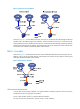
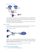
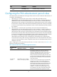
Figure 5 FCoE for I/O consolidation
As shown in Figure 5, in the traditional network, the server is connected to the LAN through an Ethernet
interface and to the SAN through an FC interface. In the FCoE network, the server is connected to the
FCoE-capable FCF switch, and then the FCF switch is connected to the LAN through an Ethernet interface
and to the SAN through an FC interface. The links between the server and the FCF switch and between
FCF switches can transmit both Ethernet frames and FC frames.
Basic concepts
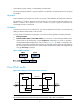
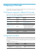
As shown in Figure 6, the links between the FCF switch and the ENode (nodes that can transport FC over
Ethernet, such as servers and disk devices) and between FCF switches can be used for receiving and
sending both Ethernet frames and FC frames.
Figure 6 FCoE network diagram
VFC interface and VN interface
A virtual fiber channel (VFC) interface is a logical interface manually created on the FCF switch to
simulate the function of a physical FC interface.
To use a VFC interface, bind it to a physical Ethernet interface.
You can connect either an ENode or an FCF switch to a VFC interface.