
R21xx-HP FlexFabric 11900 FCoE Configuration Guide


9
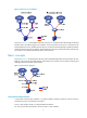
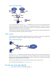
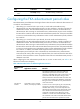
Figure 10 FCF network diagram
In an FCoE environment as shown in Figure 10, different from a pure FC network, the ENode and FCF
switch communicate over Ethernet interfaces on a lossless Ethernet network. The FCoE virtual link
between the ENode and FCF switch connects a VN interface to a VFC interface, and the FCoE virtual link
between FCF switches connects two VFC interfaces.
Each FCF switch is assigned a domain ID. Each FC SAN supports a maximum number of 239 domain IDs,
so an FC SAN cannot have more than 239 FCF switches.
NPV mode
An FC SAN needs a large number of edge switches that connect directly to nodes. N_Port Virtualization
(NPV) switches are developed to expand the number of switches in an FC SAN.
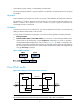
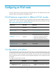
Figure 11 NPV network diagram
As shown in Figure 11, the NPV switch resides between nodes and the core switch on the edge of the
fabric. The core switch is a switch operating in FCF mode. The NPV switch is connected to the nodes
through its F_Ports and to the core switch through its NP_Port. In this manner, the NPV switch forwards
traffic from its connected nodes to the core switch.
The NPV switch appears as an FCF switch to nodes and as a node to the core switch.
For more information about NPV, see "Configuring NPV."
Protocols and standards
• FC-FS-3, Fibre Channel - Framing and Signaling - 3