
R21xx-HP FlexFabric 11900 FCoE Configuration Guide

55
0.00% packet loss
round-trip min/avg/max = 9/18/25 ms
The output shows that Switch A can reach Switch C.
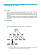
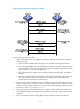
FSPF configuration example
Network requirements
As shown in Figure 19, configure FSPF to enable the two FCF switches to communicate with each other.
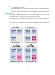
Figure 19 Network diagram
Configuration procedure
1. Configure Switch A:
# Configure Switch A to operate in advanced mode, save the configuration, and reboot Switch A.
(Skip this step if the switch is operating in advanced mode.)
<SwitchA> system-view
[SwitchA] system-working-mode advance
Do you want to change the system working mode? [Y/N]:y
The system working mode is changed, please save the configuration and reboot the
system to make it effective.
# Configure Switch A to operate in FCF mode and bind interface VFC 100 to interface
Ten-GigabitEthernet 1/0/1.
<SwitchA> system-view
[SwitchA] fcoe-mode fcf
[SwitchA] interface Vfc 100
[SwitchA-Vfc100] bind interface Ten-GigabitEthernet1/0/1
[SwitchA-Vfc100] fc mode e
[SwitchA-Vfc100] port trunk vsan 2
[SwitchA-Vfc100] quit
# Configure interface Ten-GigabitEthernet 1/0/1 to allow VLAN 10.
[SwitchA] interface ten-gigabitethernet1/0/1
[SwitchA-Ten-GigabitEthernet1/0/1] port link-type trunk
[SwitchA-Ten-GigabitEthernet1/0/1] port trunk permit vlan 10
[SwitchA-Ten-GigabitEthernet1/0/1] quit
# Enable the fabric configuration function.
[SwitchA] vsan 2
[SwitchA-vsan2] domain configure enable
# Configure the domain ID as 1.
[SwitchA-vsan2] domain-id 1 static
Non-disruptive reconfiguration or isolating the switch may be performed. Continu
e? [Y/N]:y