HP FlexFabric 11900 Switch Series Fundamentals Configuration Guide Part number: 5998-4057 Software version: Release 2105 and later Document version: 6W100-20130515
Legal and notice information © Copyright 2013 Hewlett-Packard Development Company, L.P. No part of this documentation may be reproduced or transmitted in any form or by any means without prior written consent of Hewlett-Packard Development Company, L.P. The information contained herein is subject to change without notice.
Contents Using the CLI ································································································································································ 1 CLI views ············································································································································································ 1 Entering system view from user view ·········································································································
Accessing the device through SNMP ······················································································································· 35 Configuring SNMPv3 access ········································································································································ 35 Configuring SNMPv1 or SNMPv2c access················································································································· 36 Controlling user access ···········
FTP server configuration example (in IRF mode) ································································································ 64 Using the device as an FTP client ································································································································· 65 Establishing an FTP connection ···························································································································· 65 Managing directories on the FTP server
Upgrading software ··················································································································································· 90 Overview········································································································································································· 90 Software types ··················································································································································
HTTP feature upgrade example ························································································································· 134 HTTP feature rollback example ·························································································································· 136 ISSU examples for using install series commands (in IRF mode) ············································································ 137 HTTP feature upgrade example ····························
Websites······························································································································································· 170 Conventions ·································································································································································· 171 Index ··························································································································································
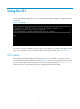
Using the CLI At the command-line interface (CLI), you can enter text commands to configure, manage, and monitor your device. Figure 1 CLI example You can use a variety of methods to log in to the CLI. For example, you can log in through the console port, or by using Telnet or SSH. For more information about login methods, see "Login overview." CLI views Commands are grouped in different views by function. To use a command, you must enter its view.
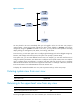
Figure 2 CLI views …… You are placed in user view immediately after you are logged in to the CLI. The user view prompt is , where Device-name indicates the device name, defaults to Sysname, and can be changed by using the sysname command. In user view, you can perform basic operations including display, debug, file management, FTP, Telnet, clock setting, and reboot.
Returning to user view You can return directly to user view from any other view by using the return command or pressing Ctrl+Z, instead of using the quit command multiple times. To return directly to user view from any other view: Task Command Return directly to user view. return Accessing the CLI online help The CLI online help is context sensitive. You can enter a question mark at any prompt or in any position of a command to display all available options.
format free ftp display ftp? ftp ftp-server ftp-user Using the undo form of a command Most configuration commands have an undo form for canceling a configuration, restoring the default, or disabling a feature. For example, the info-center enable command enables the information center, and the undo info-center enable command disables the information center.
Entering a string or text type value for an argument Generally, a string type argument value can contain any printable character (in the ASCII code range of 32 to 126) other than the question mark (?), quotation mark ("), backward slash (\), and space, and a text type argument value can contain any printable character other than the question mark. However, a specific argument might have more requirements.
Configuring and using command hotkeys The system defines the hotkeys shown in Table 2 and provides five configurable command hotkeys. Pressing a command hotkey is the same as entering a command. If a hotkey is also defined by the terminal software you are using to interact with the device, the terminal software definition takes effect. To configure a command hotkey: Step 1. Enter system view. Command Remarks system-view N/A By default: • Ctrl+G is assigned the display current-configuration command.
Hotkey Function Esc+F Moves the cursor forward one word. Esc+N Moves the cursor down one line. This hotkey is available before you press Enter. Esc+P Moves the cursor up one line. This hotkey is available before you press Enter. Esc+< Moves the cursor to the beginning of the clipboard. Esc+> Moves the cursor to the ending of the clipboard.
Using the command history function The system automatically saves commands successfully executed by a login user to two command history buffers: the command history buffer for the user interface and the command history buffer for all user interfaces. Table 4 compares these two types of command history buffers.
Pausing between screens of output The system automatically pauses after displaying a screen if the output is too long to fit on one screen. You can use the keys described in "Output controlling keys" to display more information or stop the display. By default, up to 24 lines can be displayed on a screen. You can change the maximum number of lines that can be displayed on a screen by using the screen-length screen-length command. For more information about this command, see Fundamentals Command Reference.
2: VLAN type: Static 3: Route interface: Configured 4: IP address: 192.168.2.1 5: Subnet mask: 255.255.255.0 6: Description: For LAN Access 7: Name: VLAN 0999 8: Tagged ports: 9: Untagged ports: 10: Ten-GigabitEthernet 1/0/1 None Filtering the output from a display command You can use the | { begin | exclude | include } regular-expression option to filter the display command output: • begin—Displays the first line matching the specified regular expression and all subsequent lines.
Characters [] Meaning Examples Matches a single character in the brackets. "[16A]" matches a string containing 1, 6, or A; "[1-36A]" matches a string containing 1, 2, 3, 6, or A (- is a hyphen). To match the character "]", put it immediately after "[", for example [ ]string]. There is no such limit on "[". [^] Matches a single character that is not in the brackets. "[^16A]" matches a string that contains at least one character other than 1, 6, or A, such as "abc".
user-role network-operator # user-interface vty 0 15 authentication-mode scheme user-role network-operator # ssh server enable # return # Use | exclude Direct in the display ip routing-table command to filter out direct routes and display only the non-direct routes. display ip routing-table | exclude Direct Destinations : 12 Routes : 12 Destination/Mask Proto Pre Cost NextHop Interface 2.2.2.0/24 OSPF 10 2 1.1.2.
more vlan.txt VLAN ID: 1 VLAN type: Static Route interface: Not configured Description: VLAN 0001 Name: VLAN 0001 Tagged ports: None Untagged ports: Ten-GigabitEthernet 1/0/1 # Append the VLAN 999 settings to the end of file vlan.txt. display vlan 999 >> vlan.txt # Verify whether the VLAN 999 settings are appended to the end of file vlan.txt. more vlan.
Task Command View and manage the output from a display command effectively. display command [ | [ by-linenum ] { begin | exclude | include } regular-expression ] [ > filename | >> filename ] For example: # Save the running configuration to a separate file named test.txt, with each line numbered. display current-configuration | by-linenum > test.txt # Append lines including "snmp" in the running configuration to the file test.txt. display current-configuration | include snmp >> test.
Login overview The first time you access the device, you can only log in to the CLI through the console port. After login, you can change console login parameters or configure other access methods, including Telnet, SSH, modem, and SNMP. FIPS compliance The device supports the FIPS mode that complies with NIST FIPS 140-2 requirements. Support for features, commands, and parameters might differ in FIPS mode and non-FIPS mode. For more information about FIPS mode, see Security Configuration Guide.
Login method Default settings and minimum configuration requirements By default, modem dial-in is enabled and requires a password, but no password is configured. • Logging in through a pair of modems To log in through modems, complete the following configuration tasks: • Configure a password for password authentication, or change the authentication mode and configure parameters for the new authentication mode. • Assign a user role to AUX login users (network-operator by default).
Logging in through the console port for the first device access The first time you access the device, you can only log in to the CLI through the console port. To log in through the console port, prepare a console terminal (for example, a PC) and make sure the console terminal has a terminal emulation program, for example, HyperTerminal in Windows XP. To log in through the console port: 1. Connect the DB-9 female connector of the console cable to the serial port of the PC. 2.
Figure 4 Creating a connection Figure 5 Specifying the serial port used to establish the connection 18
Figure 6 Setting the properties of the serial port 5. Power on the device and press Enter as prompted. Figure 7 Device CLI 6. At the default user view prompt , enter commands to configure the device or view the running status of the device. To get help, enter ?.
Logging in to the CLI By default, you can log in to the CLI only through the console port. After you log in, you can configure other login methods, including Telnet, SSH, and modem. To prevent illegal access to the CLI and control user behaviors, you can configure login authentication, assign user roles, configure command authorization and command accounting, and use ACLs to filter unauthorized logins.
A relative number uniquely identifies a user interface among all user interfaces that are the same type. The number format is user interface type + number. Both types of user interfaces are numbered starting from 0 and incrementing by 1. For example, the first VTY user interface is VTY 0. Login authentication modes You can configure login authentication to prevent illegal access to the device CLI. The device supports the following login authentication modes: • None—Disables authentication.
FIPS compliance The device supports the FIPS mode that complies with NIST FIPS 140-2 requirements. Support for features, commands, and parameters might differ in FIPS mode and non-FIPS mode. For more information about FIPS mode, see Security Configuration Guide. Telnet is not supported in FIPS mode. Logging in through the console port locally You can connect a terminal to the console port of the device to log in and manage the device, as shown in Figure 8.
The next time you attempt to log in through the console, you do not need to provide any username or password. Configuring password authentication for console login (not supported in FIPS mode) Step Command Remarks 1. Enter system view. system-view N/A 2. Enter AUX user interface view. user-interface aux first-number [ last-number ] N/A 3. Enable password authentication. authentication-mode password By default, authentication is disabled for the console login. 4. Set a password.
Step Command Remarks system-view N/A user-interface aux first-number [ last-number ] N/A 1. Enter system view. 2. Enter AUX interface view. 3. Set the baud rate. speed speed-value By default, the baud rate is 9600 bps. 4. Specify the check mode. parity { even | mark | none | odd | space } By default, the parity check mode is none, and no parity check is performed. 5. Specify the number of stop bits. user parity The default is 1. stopbits { 1 | 1.
Step Command Remarks The default is 10 minutes. 13. Set the session idle-timeout timer. idle-timeout minutes [ seconds ] If there is no interaction between the device and the user within the idle-timeout interval, the system automatically terminates the user connection on the user interface. If you set the idle-timeout timer to 0, the session will not be aged out.
The next time you attempt to Telnet to the device, you do not need to provide any username or password, as shown in Figure 9. If the maximum number of login users has been reached, your login attempt fails and the message "All user interfaces are used, please try later!" appears. Figure 9 Telnetting to the device without authentication Configuring password authentication for Telnet login Step Command Remarks 1. Enter system view. system-view N/A 2. Enable Telnet server.
Figure 10 Password authentication interface for Telnet login Configuring scheme authentication for Telnet login Step Command Remarks 1. Enter system view. system-view N/A 2. Enable Telnet server. telnet server enable By default, the Telnet server function is disabled. 3. Enter one or multiple VTY user interface views. user-interface vty first-number [ last-number ] N/A 4. Enable authentication.
Configuring common VTY user interface settings For a VTY user interface, you can specify a command that is to be automatically executed when a user logs in. After executing the specified command and performing the incurred task, the system automatically disconnects the Telnet session. Before you configure this function and save the configuration, make sure you can access the CLI through a different user interface. Typically, you configure the auto-execute command telnet X.X.X.
Using the device to log in to a Telnet server You can use the device as a Telnet client to log in to a Telnet server. If the server is located in a different subnet than the device, make sure the two devices have routes to reach each other. Figure 12 Telnetting from the device to a Telnet server To use the device to log in to a Telnet server: Step Command Remarks system-view N/A (Optional.) Specify the source IPv4 address or source interface for outgoing Telnet packets.
To configure SSH login on the device: Step Command Remarks system-view N/A public-key local create { dsa | rsa } By default, no local key pairs are created. Enable SSH server. ssh server enable By default, SSH server is disabled. 4. Create an SSH user and specify the authentication mode. ssh user username service-type stelnet authentication-type { password | { any | password-publickey | publickey } assign publickey keyname } By default, no SSH user is configured on the device. 5.
To work with the SSH server, you might need to configure the SSH client. For information about configuring the SSH client, see Security Configuration Guide. Logging in through a pair of modems You can use a pair of modems to remotely connect to the console port of the device over PSTN when the IP network connection is broken. Figure 14 Connecting to the device through modems By default, modem dial-in is enabled and requires a password, but no password is configured.
6. Launch the terminal emulation program on the PC and create a connection using the telephone number of the device-side modem. Figure 16 through Figure 19 show the configuration procedure in Windows XP HyperTerminal. On Windows Server 2003, add the HyperTerminal program first, and then log in to and manage the device as described in this document.
Figure 18 Dialing the number 8. After you hear the dial tone, press Enter as prompted. If the authentication mode is none, the prompt appears. If the authentication mode is password or scheme, you must enter the correct authentication information as prompted. Figure 19 Login page IMPORTANT: Do not directly close the HyperTerminal. Doing so can cause some modems to stay in use, and your subsequent dial-in attempts will always fail.
Displaying and maintaining CLI login Execute display commands in any view and the other commands in user view. Task Command Remarks Display information about the user interfaces that are being used. display users N/A Display information about all user interfaces the device supports. display users all N/A Display user interface information.
Accessing the device through SNMP You can run SNMP on an NMS to access the device MIB and perform GET and SET operations to manage and monitor the device. Figure 20 SNMP access diagram Get/Set requests NMS Get/Set responses and Traps MIB Agent The device supports SNMPv1, SNMPv2c, and SNMPv3, and can work with various network management software products, including IMC. However, the device and the NMS must use the same SNMP version.
Step 5. Create an SNMPv3 user. Command Remarks snmp-agent usm-user v3 user-name group-name [ remote { ip-address | ipv6 ipv6-address } [ vpn-instance vpn-instance-name ] ] [ { cipher | simple } authentication-mode { md5 | sha } auth-password [ privacy-mode { aes128 | des56 } priv-password ] ] [ acl acl-number | acl ipv6 ipv6-acl-number ] * To send informs to an SNMPv3 NMS, you must use the remote ip-address option to specify the IP address of the NMS.
Controlling user access Use ACLs to prevent unauthorized access and configure command authorization and accounting to monitor and control user behaviors. For more information about ACLs, see ACL and QoS Configuration Guide. FIPS compliance The device supports the FIPS mode that complies with NIST FIPS 140-2 requirements. Support for features, commands, and parameters might differ in FIPS mode and non-FIPS mode. For more information about FIPS mode, see Security Configuration Guide.
Configuration example Network requirements Configure the device in Figure 21 to permit only Telnet packets sourced from Host A and Host B. Figure 21 Network diagram Configuration procedure # Configure an ACL to permit packets sourced from Host A and Host B. system-view [Sysname] acl number 2000 match-order config [Sysname-acl-basic-2000] rule 1 permit source 10.110.100.52 0 [Sysname-acl-basic-2000] rule 2 permit source 10.110.100.
Step Command Remarks • SNMP community: snmp-agent community { read | write } community-name [ mib-view view-name ] [ acl acl-number | acl ipv6 ipv6-acl-number ] * • SNMPv1/v2c group: snmp-agent group { v1 | v2c } group-name [ read-view view-name ] [ write-view view-name ] [ notify-view view-name ] [ acl acl-number | acl ipv6 ipv6-acl-number ] * • SNMPv3 group: 2. Apply the ACL to an SNMP community, group, or user.
[Sysname-acl-basic-2000] rule 2 permit source 10.110.100.46 0 [Sysname-acl-basic-2000] quit # Associate the ACL with the SNMP community and the SNMP group. [Sysname] snmp-agent community read aaa acl 2000 [Sysname] snmp-agent group v2c groupa acl 2000 [Sysname] snmp-agent usm-user v2c usera groupa acl 2000 Configuring command authorization By default, commands are available for a user depending only on that user's user roles.
authorization are enabled, only authorized commands that are executed are recorded on the HWTACACS server. This section provides only the procedure for configuring command accounting. To make the command accounting function take effect, you must configure a command accounting method in ISP domain view. For more information, see Security Configuration Guide. Configuration procedure To configure command accounting: Step Command Remarks 1. Enter system view. system-view N/A 2. Enter view.
Configuring RBAC Role based access control (RBAC) controls user access to commands and resources based on user role. This chapter describes the basic idea of RBAC and guides you through the RBAC configuration procedure. Overview On devices that support multiple users, RBAC is used to assign command and resource access permissions to user roles that are created for different job functions. Users are given permission to access a set of commands and resources based on their user roles.
A user role can have multiple rules uniquely identified by rule numbers. The set of permitted commands in these rules are accessible to the user role. If two rules conflict, the one with higher number takes effect. For example, if rule 1 permits the ping command, rule 2 permits the tracert command, and rule 3 denies the ping command, the user role can use the tracert command but not the ping command.
Assigning user roles You assign access rights to users by assigning at least one user role. The users can use the collection of commands and resources accessible to any user role assigned to them. For example, user role A denies access to the qos apply policy command and permits access to only interface Ten-GigabitEthernet 1/0/1, and user role B permits access to the qos apply policy command and all interfaces. With these two user roles, you can access any interface to use the qos apply policy command.
Step 1. Enter system view. Command Remarks system-view N/A 2. Create a user role and enter user role view. role name role-name By default, the system has 18 predefined user roles: network-admin, network-operator, and level-n (where n equals an integer in the range 0 to 15). Among these user roles, only the permissions and description of the user roles level-0 to level-14 are configurable. 3. (Optional.) Configure a description for the user role.
Configuring feature groups Use feature groups to bulk assign command access permissions to sets of features. In addition to the predefined feature groups, you can create up to 64 custom feature groups and assign a feature to multiple feature groups. To configure a feature group: Step 1. Enter system view. Command Remarks system-view N/A By default, the system has the following predefined feature groups: 2. Create a feature group and enter feature group view.
Step 4. Command (Optional.) Specify a list of interfaces accessible to the user role. Remarks permit interface interface-list By default, no accessible interfaces are configured. To add more accessible interfaces, repeat this step. Changing the VLAN policy of a user role Step Command Remarks 1. Enter system view. system-view N/A 2. Enter user role view. role name role-name N/A 3. Enter user role VLAN policy view. 4. (Optional.) Specify a list of VLANs accessible to the user role.
Enabling the default user role function An AAA authentication user must have at least one user role to log in to the device. The default user role function assigns the network-operator user role to a local or remote AAA authenticated user if the AAA server has not authorized the user to use any user roles. Without the function, AAA authenticated users cannot access the system if they have no user role authorization.
Assigning user roles to non-AAA authentication users on user interfaces Specify user roles for the following two types of login users on the user interfaces: • Users that use password authentication or no authentication. • SSH clients that use publickey or password-publickey authentication. User roles assigned to these SSH clients are specified in their respective local management user accounts. For more information about user interfaces, see "Login overview" and "Logging in to the CLI.
In this method, the username you enter is ignored. You can pass authentication as long as the password is correct. If you execute the quit command after switching to a user role, you are logged out of the current user interface. • Table 10 Authentication modes for user role switching Keywords Authentication mode Description local Local password authentication only (local-only) The device uses the locally configured switching password for authentication.
Perform the following task in user view: Task Command Remarks Switch the user role. super [ rolename] The user role switching fails after three consecutive unsuccessful password attempts. Displaying RBAC settings Execute display commands in any view. Task Command Display user role information. display role [ name role-name ] Display user role feature information. display role feature [ name feature-name | verbose ] Display user role feature group information.
# Enable Telnet server. [Switch] telnet server enable # Enable scheme authentication on the user interfaces for Telnet users. [Switch] user-interface vty 0 15 [Switch-ui-vty0-15] authentication-mode scheme [Switch-ui-vty0-15] quit # Enable local authentication and authorization for the ISP domain bbb. [Switch] domain bbb [Switch-isp-bbb] authentication login local [Switch-isp-bbb] authorization login local [Switch-isp-bbb] quit # Create the user role role1.
Permission denied. # Verify that you can use all read commands of any feature. This example uses display clock. [Switch] display clock 09:31:56 UTC Sat 01/01/2011 [Switch] quit # Verify that you cannot use the write or execute commands of any feature. debugging role all Permission denied. ping 192.168.1.58 Permission denied. RBAC configuration example for RADIUS authentication users Unless otherwise noted, devices in the configuration example are operating in non-FIPS mode.
[Switch-Vlan-interface2] ip address 192.168.1.70 255.255.255.0 [Switch-Vlan-interface2] quit # Assign VLAN interface 3 an IP address from the same subnet as the RADIUS server. [Switch] interface vlan-interface 3 [Switch-Vlan-interface3] ip address 10.1.1.2 255.255.255.0 [Switch-Vlan-interface3] quit # Enable Telnet server. [Switch] telnet server enable # Enable scheme authentication on the user interfaces for Telnet users.
# Configure rule 4 to permit the user role to create VLANs and use all commands available in VLAN view. [Switch-role-role2] rule 4 permit command system-view ; vlan * # Configure rule 5 to permit the user role to enter interface view and use all commands available in interface view. [Switch-role-role2] rule 5 permit command system-view ; interface * # Configure the user role VLAN policy to disable configuration of any VLAN except VLANs 1 to 20.
# Verify that you cannot configure any interface except Ten-GigabitEthernet 1/0/1 to Ten-GigabitEthernet 1/0/24. Take Ten-GigabitEthernet 1/0/2 and Ten-GigabitEthernet 1/0/25 as examples. [Switch] vlan 10 [Switch-vlan10] port ten-gigabitethernet 1/0/2 [Switch-vlan10] port ten-gigabitethernet 1/0/25 Permission denied. RBAC configuration example for HWTACACS authentication users Unless otherwise noted, devices in the configuration example are operating in non-FIPS mode.
[Switch] user-interface vty 0 15 [Switch-ui-vty0-15] authentication-mode scheme [Switch-ui-vty0-15] quit # Enable remote-then-local authentication for user role switching. [Switch] super authentication-mode scheme local # Create the HWTACACS scheme hwtac and enter its view. [Switch] hwtacacs scheme hwtac # Specify the primary authentication server address 10.1.1.1 and the service port 49 in the scheme. [Switch-hwtacacs-hwtac] primary authentication 10.1.1.
Figure 26 Configuring advanced TACACS+ settings Verifying the configuration 1. Telnet to the switch, and enter the username test@bbb and password aabbcc to access the user interface. Verify that you have access to diagnostic commands. telnet 192.168.1.70 Trying 192.168.1.70 ... Press CTRL+K to abort Connected to 192.168.1.59 ... ****************************************************************************** Copyright (c) 2010-2013 Hewlett-Packard Development Company, L.P.
# Use the super password to switch the user role. When the system prompts for a username and password, enter the username test@bbb and password enabpass. super level-3 Username: test@bbb Password: The following output shows that you have switched the user role to level-3. User privilege role is level-3, and only those commands that authorized to the role can be used. # If the ACS server does not respond, enter the local authentication password 654321 at the prompt.
• Configure the role default-role enable command so a RADIUS user can log in with the default user role when no user role is assigned by the RADIUS server. • Add the user role authorization attributes on the RADIUS server.
Configuring FTP File Transfer Protocol (FTP) is an application layer protocol based on the client/server model. It is used to transfer files from one host to another over an IP network. FTP server uses TCP port 20 to transfer data and TCP port 21 to transfer control commands. For more information about FTP, see RFC 959. FTP supports the following transfer modes: • Binary mode—Used to transfer image files, such as .ipe, .bin, and .btw files. • ASCII mode—Used to transfer text files, such as .txt, .
Step (Optional.) Use an ACL to control access to the FTP server. 3. Command Remarks ftp server acl { acl-number | ipv6 acl-number6 } By default, no ACL is used for access control. The default idle-timeout interval is 30 minutes. (Optional.) Configure the idle-timeout interval. 4. If no data is transferred between the FTP server and FTP client within the idle-timeout interval, the connection is terminated.
FTP server configuration example (in standalone mode) Network requirements Create a local user account with username abc and password 123456 on the FTP server. Use the user account to log in to the FTP server from the FTP client, upload the file temp.bin from the FTP client to the FTP server, and download the configuration file startup.cfg from the FTP server to the FTP client for backup. Figure 28 Network diagram Configuration procedure 1.
delete /unreserved flash:/backup.bin 3. Perform FTP operations from the PC (FTP client): # Log in to the FTP server at 1.1.1.1 using the username abc and password 123456. c:\> ftp 1.1.1.1 Connected to 1.1.1.1 (1.1.1.1). 220 FTP service ready. User(1.1.1.1:(none)):abc 331 Password required for abc. Password: 230 User logged in. # Use the ASCII mode to download the configuration file startup.cfg from the device to the PC for backup. ftp> ascii 200 TYPE is now ASCII ftp> get startup.
2. Configure the FTP server: # Examine the storage space on the member devices for insufficiency. If no sufficient free space is available, use the delete/unreserved file-url command to delete unused files. (Details not shown.) # Create a local user account abc, set the password to 123456, the user role to network-admin, the working directory to the Flash root directory of the IRF fabric's active MPU, and the service type to FTP.
To establish an IPv4 FTP connection: Step Command Remarks system-view N/A 1. Enter system view. 2. (Optional.) Specify a source IP address for outgoing FTP packets. ftp client source { interface interface-type interface-number | ip source-ip-address } By default, no source IP address is specified, and the primary IP address of the output interface is used as the source IP address. 3. Return to user view. quit N/A • Log in to the FTP server directly from 4.
Managing directories on the FTP server Task Command • Display the detailed information of a directory or file Display directory and file information on the FTP server. on the FTP server: dir [ remotefile [ localfile ] ] • Display the name of a directory or file on the FTP server: ls [ remotefile [ localfile ] ] Change the working directory on the FTP server. cd { directory | .. | / } Return to the upper level directory on the FTP server. cdup Display the working directory that is being accessed.
Task Command Remarks Set the file transfer mode to binary. binary The default file transfer mode is ASCII. Set the FTP operation mode to passive. passive The default mode is passive. Display or change the local working directory of the FTP client. lcd [ directory | / ] N/A Upload a file to the FTP server. put localfile [ remotefile ] N/A Download a file from the FTP server. get remotefile [ localfile ] N/A Add the content of a file on the FTP client to a file on the FTP server.
Task Command Remarks Enable or disable FTP client debugging. debug By default, FTP client debugging is disabled. Clear the reply information in the buffer. reset N/A Terminating the FTP connection Task Command Remarks Terminate the connection to the FTP server without exiting FTP client view. • disconnect • close Use either command in FTP client view. Terminate the connection to the FTP server and return to user view. • bye • quit Use either command in FTP client view.
Figure 30 Network diagram Configuration procedure # Configure IP addresses as shown in Figure 30 and make sure the device and PC can reach each other. (Details not shown.) # Examine the storage space of the device for insufficiency. If no sufficient free space is available, use the delete/unreserved file-url command to delete unused files. (Details not shown.) # Log in to the FTP server at 10.1.1.1 using the username abc and password 123456. ftp 10.1.1.1 Connected to 10.1.1.1 (10.1.1.1).
FTP client configuration example (in IRF mode) Network requirements • Use the IRF fabric that comprises two member devices as the FTP client and the PC as the FTP server. • Log in to the FTP server from the FTP client using the user account with username abc and password 123456 (which has been created on the PC). • Download the file temp.bin from the FTP server to the FTP client, and upload the configuration file config.cfg from the FTP client to the FTP server for backup.
# Download the file temp.bin from the PC to the Flash root directory of the IRF fabric's standby MPUs. (In this example, the IRF fabric has three standby MPUs: one in slot 1 of member device 1, one in slot 0 of member device 2, and one in slot 1 of member device 2.) ftp> get temp.bin chassis1#slot1#flash:/temp.bin ftp> get temp.bin chassis2#slot0#flash:/temp.bin ftp> get temp.bin chassis2#slot1#flash:/temp.bin # Upload the configuration file config.cfg from the IRF fabric to the PC for backup.
Configuring TFTP Trivial File Transfer Protocol (TFTP) is a simplified version of FTP for file transfer over secure reliable networks. TFTP uses UDP port 69 for data transmission. In contrast to TCP-based FTP, TFTP does not require authentication or complex message exchanges, and is easier to deploy. TFTP is suited for reliable network environments. The device can only operate as a TFTP client. You can upload a file from the device to the TFTP server or download a file from the TFTP server to the device.
Configuring the device as an IPv6 TFTP client Step Command Remarks 1. Enter system view. system-view N/A 2. (Optional.) Use an ACL to control the client's access to TFTP servers. tftp-server ipv6 acl acl-number By default, no ACL is used for access control. 3. Specify the source IPv6 address for TFTP packets sent by the TFTP client. tftp client ipv6 source { interface interface-type interface-number | ipv6 source-ip-address } By default, no source IPv6 address is specified.
Managing the file system This chapter describes how to manage the device's file system, including the storage media, directories, and files. IMPORTANT: • Before managing storage media, files, and directories, make sure you know the possible impacts. • A file or directory whose name starts with a period (.) is considered a hidden file or directory. Do not give a common file or directory a name that starts with a period. • Some system files and directories are hidden.
Table 12 File name formats in IRF mode Format file-name Description Example Specifies a file in the current working directory. Specifies a file in a specific folder in the current working directory. [path/]file-name The path argument represents the path to the file. If the file is in a single-level folder, specify the folder name for the argument. If the file is in a nested folder, separate each folder name by a forward slash (/). a.cfg indicates a file named a.cfg in the current working directory.
Displaying file information Perform this task in user view. Task Command Display folder or file information. dir [ /all ] [ file-url | /all-filesystems ] Displaying the contents of a text file Perform this task in user view. Task Command Display the contents of a text file. more file-url Renaming a file Perform this task in user view. Task Command Rename a file. rename fileurl-source fileurl-dest Copying a file Perform this task in user view. Task Command Copy a file.
Deleting/restoring a file You can delete a file permanently or move it to the recycle bin. A file moved to the recycle bin can be restored, but a permanently deleted file cannot. Files in the recycle bin occupy storage space. To release the occupied space, execute the reset recycle-bin command in user view. To save storage space, periodically empty the recycle bin with the reset recycle-bin command. Perform the following tasks in user view: Task Command Delete a file by moving it to the recycle bin.
Task Command Display directory or file information. dir [ /all ] [ file-url | /all-filesystems ] Displaying the current working directory Perform this task in user view. Task Command Display the current working directory. pwd Changing the current working directory Perform this task in user view. Task Command Change the current working directory. cd { directory | .. | / } Creating a directory Perform this task in user view. Task Command Create a directory.
Perform this task in user view. Task Command Repair a storage medium. fixdisk medium-name Formatting a storage medium CAUTION: After a storage medium is formatted, all files and directories on it are erased and cannot be restored. Before formatting a storage medium, make sure no other administrators are accessing the storage medium. Otherwise, the format operation fails. Perform this task in user view. Task Command Format a storage medium.
Managing configuration files You can use the CLI or the Boot menu to manage configuration files. This chapter only explains how to manage configuration files from the CLI. Overview A configuration file saves a set of commands for configuring software features on the device. You can save any configuration to a configuration file so they can survive a reboot. You can also back up configuration files to a host for future use.
To view the running configuration, including settings that have not been saved yet, use the display current-configuration command. The displayed configuration does not include parameters that use initial settings or settings in the default configuration file. Startup configuration loading process Figure 33 shows the configuration loading process during startup.
c. If you have not specified a backup startup configuration file, or the specified backup startup configuration file is not available, the device starts up with the default configuration file (called "factory defaults"). If a parameter is not included in the default configuration file, its initial setting is loaded. Configuration file formats Configuration files you specify for saving configuration must use the .cfg extension. A .cfg configuration file is a human-readable text file.
tnl-policy test vpn-target 105:1 export-extcommunity vpn-target 105:1 import-extcommunity # ftp server enable # telnet server enable # switch-mode normal chassis 1 slot 2 switch-mode mix-bridging-routing chassis 1 slot 3 # fcoe-mode fcf # local-user 123 class manage password hash $h$6$xLkS97tXVy9Oq8lo$19Lej8XTwS9wdP+0kV4y1hJbusRjoL06KfbSOU7sOWO eFHkH5WWG18cabl5MZ9TSWAc8rZVhSfdVA7xx5jY5Rw== service-type ftp authorization-attribute work-directory flash:/ authorization-attribute user-role network-operator aut
IMPORTANT: • Do not move or copy a private-key-encrypted configuration file between MPUs. These actions can cause a decryption failure because the MPUs use different private keys. • When the configuration encryption function is enabled, you cannot convert the operating mode between standalone and IRF. Before converting the operating mode, you must first disable the configuration encryption function. To enable configuration encryption: Step Command Remarks 1. Enter system view. system-view N/A 2.
Task Command Remarks If you execute the save [ safely ] command without specifying any other keyword, the command saves the configuration to the main startup configuration file. Save the running configuration to a configuration file in the root directory of each MPU's flash and specify the file as a startup configuration file. save [ safely ] [ backup | main ] [ force ] If the force keyword is specified, the command saves the configuration to the next-startup configuration file that has been specified.
Task Specify a next-startup configuration file. Command Remarks startup saved-configuration cfgfile [ backup | main ] Use the display startup command and the display saved-configuration command in any view to verify the configuration. Backing up the main next-startup configuration file to a TFTP server Before performing this task, make sure the following requirements are met: • The server is reachable and enabled with TFTP service. • You have read and write permissions.
Step Command Remarks 1. Restore the main next-startup configuration file from a TFTP server in user view. restore startup-configuration from src-addr src-filename This command is not supported in FIPS mode. 2. (Optional.) Verify that the specified configuration file has been set as the main next-startup configuration file.
Task Command Display names of the configuration files used at this startup and the next startup. display startup Display the valid configuration in the current view.
Upgrading software This chapter describes types of software and how to upgrade software from the CLI without performing ISSU. For a comparison of all software upgrade methods, see "Upgrade methods." Overview Software upgrade enables you to have new features and fix bugs. Before performing an upgrade, use the release notes for the new software version to verify software and hardware compatibility and evaluate upgrade impacts. Software types The following software types are available: • BootWare image—A .
Comware image redundancy and loading procedure You can specify two sets of Comware software images: one main and one backup. The system always attempts to start up with the main images. If any main image does not exist or is invalid, the system tries the backup images. Figure 34 shows the entire Comware image loading procedure. This procedure assumes that the main image set and the backup image set have feature packages and patch packages.
Figure 35 System startup process Start BootWare runs Press Ctrl+B promptly? Yes Enter Boot menu to upgrade BootWare or startup software images No Startup software images run System starts up and CLI appears. Finish Upgrade methods Upgrading method Software types Remarks Upgrading from the CLI: Non-ISSU method • BootWare image • Comware images (excluding patches) This method is disruptive. You must reboot the entire device to complete the upgrade.
Non-ISSU upgrade procedure summary To upgrade software from the CLI without using ISSU: 1. Download the upgrade software image file. 2. (Optional.) Preload the BootWare image to the BootWare. If a BootWare upgrade is required, you can perform this task to shorten the subsequent upgrade time. This task helps avoid upgrade problems caused by unexpected electricity failure. If you skip this task, the device automatically upgrades the BootWare when upgrading the startup software images.
Task Command Remarks Specify the downloaded software image file for the file-url argument. • In standalone mode: Load the upgrade BootWare image from the flash to the Normal area of BootWare. bootrom update file file-url slot slot-number-list • In IRF mode: bootrom update file file-url chassis chassis-number slot slot-number-list When executing this command, the device examines the upgrade BootWare image for version and hardware compatibility.
Step Command Remarks To use method 3: • If the active MPU has started up Method 1: boot-loader file ipe-filename slot slot-number { backup | main } Method 2: 2. Specify main or backup startup images for the standby MPU. boot-loader file boot boot-package system system-package [ feature feature-package&<1-30> ] slot slot-number { backup | main } Method 3: boot-loader update slot slot-number Method 4: See "Enabling software synchronization from the active MPU to the standby MPU at startup." 3.
Step Command Remarks Method 1: You can also specify a backup startup image file. boot-loader file ipe-filename chassis chassis-number slot slot-number { backup | main } 1. Specify the upgrade file as the main startup image file for the global active MPU. Method 2: boot-loader file boot boot-package system system-package [ feature feature-package&<1-30> ] chassis chassis-number slot slot-number { backup | main } To use method 1, the file name must take the storage-medium:/base-filename.
Enabling software synchronization from the active MPU to the standby MPU at startup This feature is available only when the device is operating in standalone mode. To synchronize software from the global active MPU to other MPUs on an IRF fabric, use the irf auto-update enable command. For more information about software auto-update, see IRF Configuration Guide.
Non-ISSU software upgrade example (for standalone mode) Network requirements The device has two MPUs: one active MPU in slot 4 and one standby MPU in slot 5. Use the file startup-a2105.ipe to upgrade software images for the device. Figure 36 Network diagram TFTP server TFTP client 1.1.1.1/24 2.2.2.2/24 Internet Device Configuration procedure # Configure IP addresses and routes to make sure the device and the TFTP server can reach each other. (Details not shown.
# Verify that the device is running the correct software. display version Non-ISSU software upgrade example (for IRF mode) Network requirements Use the file startup-a2105.ipe to upgrade software images for the IRF fabric in Figure 37. Each IRF member device has two MPUs: one in slot 4 and one in slot 5. The global active MPU is in slot 4 on the master device. Figure 37 Network diagram Master (Member ID = 1) Internet Subordinate (Member ID = 2) IRF link IRF 1.1.1.1/24 2.2.2.
boot-loader file flash:/startup-a2105.ipe chassis 1 slot 4 main boot-loader file flash:/startup-a2105.ipe chassis 1 slot 5 main boot-loader file flash:/startup-a2105.ipe chassis 2 slot 4 main boot-loader file flash:/startup-a2105.ipe chassis 2 slot 5 main # Specify startup-a2105-backup.ipe as the backup startup image file for all MPUs. boot-loader file flash:/startup-a2105-backup.
ISSU overview The In-Service Software Upgrade (ISSU) function enables software upgrade with the least downtime. During an ISSU, you can perform version rollback and use display commands to view the version compatibility and upgrade status. ISSU is implemented on the basis of the following design advantages: • Separation of service features from basic functions. The software of the device includes a boot image, a system image, some feature images, and some patch images (if any).
forwarding packets. After startup, the CPU continues to provide services on the basis of the saved system information. For services that require regular protocol message exchanges to maintain connections, this method starts protocol agents to meet the requirements. Compared with an incremental upgrade, an ISSU reboot upgrade affects all modules that use the CPU and takes a longer time. • Reboot (in standalone mode): A reboot upgrade reboots cards to load the new software.
• Verify that the storage media on the MPUs have enough free space for the .ipe file and the new image files. • Use the display device command to verify that the system is operating correctly. If there is any problem with the system, troubleshoot the system before performing an ISSU. • Use the save command to save the running configuration. • In standalone mode, use FTP or TFTP to transfer the software image files (in .bin or .ipe) to the root directory of the active MPU's storage medium.
• To configure the device after an ISSU, you must log in again to the device.
Performing an ISSU by using issu series commands Performing an ISSU in standalone mode When you use the issu series commands to install or upgrade the software of MPUs, the device automatically install or upgrade the software of the LPUs and switching fabric cards as needed. You do not need to install or upgrade the software of the LPUs and switching fabric cards separately. The ISSU procedure varies depending on whether the device has a single or two MPUs.
Step 6. (Optional.) Accept the upgrade and delete the automatic-rollback timer. Command Remarks issu accept N/A • To upgrade the original active 7. Complete the ISSU process or roll back to the original software configuration. MPU and complete the ISSU: issu commit slot slot-number • To roll back to the original software configuration: issu rollback Specify the slot number of the original active MPU for the slot slot-number option.
Step 1. Command Upgrade the MPU and configure the upgrade images as the main startup software images for the MPU. Remarks • Method 1: issu load file { boot filename | system filename | feature filename&<1-30> } * slot slot-number • Method 2: Specify the slot number of the only MPU for the slot slot-number option. issu load file ipe ipe-filename slot slot-number Specify the slot number of the only MPU for the slot slot-number option. 2.
Before upgrade, use the display version comp-matrix file { boot filename | system filename | feature filename&<1-30> } * or the display version comp-matrix file ipe ipe-filename command to display the compatibility between the new and old images as well as the upgrade methods to be used: • If a new image is on the Version compatibility list, the new and old images are compatible. • If a new image is not on the Version compatibility list, the new and old images are incompatible.
Step Command Upgrade subordinate members and configure the upgrade images as the main startup software images for the subordinate members. 1. Remarks • Method 1: issu load file { boot filename | system filename | feature filename&<1-30> } * chassis chassis-number&<1-3> • Method 2: issu load file ipe ipe-filename chassis chassis-number&<1-3> • To complete the ISSU process, Complete the ISSU process or roll back to the original software configuration. 2.
Step Command Remarks • Method 1: 4. 5. 6. Upgrade the global standby MPU and configure the upgrade images as the startup software images for the MPU. issu load file { boot filename | system filename | feature filename&<1-30> } * chassis chassis-number slot slot-number • Method 2: issu load file ipe ipe-filename chassis chassis-number slot slot-number Perform an active/standby switchover and upgrade the LPUs and switching fabric cards. issu run switchover N/A (Optional.
Step 2. Complete the ISSU process or roll back to the original software configuration. Command Remarks • To upgrade the original global active After all cards are upgraded, the ISSU process ends and the ISSU status transitions to Init. • To roll back to the original software During this ISSU process, automatic rollback is not supported, but you can use the issu rollback command to manually roll back to the original software configuration.
Task Upgrade the MPU and configure the upgrade images as the startup software images for the MPU. Command Remarks • Method 1: Specify the member ID and slot number of the only MPU for the chassis chassis-number slot slot-number option. issu load file { boot filename | system filename | feature filename&<1-30> } * chassis chassis-number slot slot-number • Method 2: issu load file ipe ipe-filename chassis chassis-number slot slot-number This single command starts and finishes the ISSU process.
Task Command Display ISSU status information. display issu state Display automatic-rollback timer information. display issu rollback-timer Display active software images. display install active [ chassis chassis-number slot slot-number ] [ verbose ] Display inactive software images. display install inactive [ chassis chassis-number slot slot-number ] [ verbose ] Display main startup software images.
100 256k 100 256k 0 0 764k 0 --:--:-- --:--:-- --:--:-- 810k # Display active software images. display install active Active packages on slot 4: flash:/boot-r0201.bin flash:/system-r0201.bin flash:/http-r0201.bin Active packages on slot 5: flash:/boot-r0201.bin flash:/system-r0201.bin flash:/http-r0201.bin # Check for the ISSU method to be used for the upgrade and view the possible impact of the upgrade. display version comp-matrix file feature flash:/http-r0202.
5 Service Upgrade Upgrading software images to compatible versions. Continue? [Y/N]: y # Perform an active/standby switchover. issu run switchover Upgrade summary according to following table: flash:/http-r0202.bin Running Version New Version Alpha 0201 Alpha 0202 Slot Switchover Way 4 Active standby process switchover Upgrading software images to compatible versions. Continue? [Y/N]: y # Upgrade the feature on the original active MPU.
Figure 39 Network diagram Upgrade procedure # Download the image file that contains the R0202 HTTP feature from the TFTP server. tftp 2.2.2.2 get http-r0202.bin % Total 100 256k % Received % Xferd 100 256k 0 Average Speed Time Time Time Current Dload Total Spent Left Speed 0 Upload 764k 0 --:--:-- --:--:-- --:--:-- 810k # Display active software images. display install active Active packages on slot 4: flash:/boot-r0201.bin flash:/system-r0201.
Slot Upgrade Way 5 Reboot Upgrading software images to incompatible versions. Continue? [Y/N]: y # Upgrade the feature on the original active MPU. issu run switchover Upgrade summary according to following table: flash:/http-r0202.bin Running Version New Version Alpha 0201 Alpha 0202 Slot Upgrade Way 4 Reboot Upgrading software images to incompatible versions. Continue? [Y/N]: y # Verify that both MPUs are running the new HTTP image.
display install active Active packages on slot 4: flash:/boot-r0201.bin flash:/system-r0201.bin flash:/http-r0201.bin Active packages on slot 5: flash:/boot-r0201.bin flash:/system-r0201.bin flash:/http-r0201.bin # Check for the ISSU method to be used for the upgrade and view the possible impact of the upgrade. display version comp-matrix file feature flash:/http-r0202.bin Feature image: flash:/http-r0202.
# Perform an active/standby switchover. issu run switchover Upgrade summary according to following table: flash:/http-r0202.bin Running Version New Version Alpha 0201 Alpha 0202 Slot Switchover Way 4 Active standby process switchover Upgrading software images to compatible versions. Continue? [Y/N]: y # Display active software images. display install active Active packages on slot 4: flash:/boot-r0201.bin flash:/system-r0201.bin flash:/http-r0201.
Upgrade the HTTP feature from R0201 to R0202. Figure 41 Network diagram Upgrade procedure # Download the image file that contains the R0202 HTTP feature from the TFTP server. tftp 2.2.2.2 get http-r0202.bin % Total 100 256k % Received % Xferd 100 256k 0 0 Average Speed Time Time Time Current Dload Total Spent Left Speed Upload 764k 0 --:--:-- --:--:-- --:--:-- 810k # Display active software images.
Version Dependency System List: V700R001B31D001 V700R001B31D002 Chassis Slot Upgrade Way 1 4 Service Upgrade 1 5 Service Upgrade 2 4 Service Upgrade 2 5 Service Upgrade Influenced service according to following table on chassis 1 slot 4: flash:/http-r0202.bin HTTP CFA Influenced service according to following table on chassis 1 slot 5: flash:/http-r0202.bin HTTP CFA Influenced service according to following table on chassis 2 slot 4: flash:/http-r0202.
Upgrading software images to compatible versions. Continue? [Y/N]: y # Upgrade the feature on the original master. issu commit chassis 1 Upgrade summary according to following table: flash:/http-r0202.bin Running Version New Version Alpha 0201 Alpha 0202 Chassis Slot Upgrade Way 1 4 Service Upgrade 1 5 Service Upgrade Upgrading software images to compatible versions. Continue? [Y/N]: y # Verify that both members are running the new HTTP image.
Figure 42 Network diagram Upgrade procedure # Download the image file that contains the R0202 HTTP feature from the TFTP server. tftp 2.2.2.2 get http-r0202.bin % Total 100 256k % Received % Xferd 100 256k 0 Average Speed Time Time Time Current Dload Total Spent Left Speed 0 Upload 764k 0 --:--:-- --:--:-- --:--:-- 810k # Display active software images. display install active Active packages on chassis 1 slot 4: flash:/boot-r0201.bin flash:/system-r0201.
V700R001B31D002 This feature image is not compliant with the system image. The output shows that the two versions are incompatible. The cards will be rebooted for the upgrade. # Upgrade the HTTP feature on the subordinate member. After the upgrade, the subordinate member will leave the original IRF fabric and form a new IRF fabric by itself. issu load file feature flash:/http-r0202.
flash:/system-r0201.bin flash:/http-r0202.bin HTTP feature rollback example Rollback requirement The IRF fabric comprises two members: the master member with the member ID 1 and the subordinate member with the member ID 2. Each member has one MPU in slot 4 (active MPU) and one MPU in slot 5 (standby MPU). Roll back the HTTP feature from R0202 to R0201 after upgrading it from R0201 to R0202.
flash:/http-r0201.bin # Check for the ISSU method to be used for the upgrade and view the possible impact of the upgrade. display version comp-matrix file feature flash:/http-r0202.bin Feature image: flash:/http-r0202.
# Perform a master/subordinate switchover. issu run switchover Upgrade summary according to following table: flash:/http-r0202.bin Running Version New Version Alpha 0201 Alpha 0202 Chassis Slot Switchover Way 1 4 Active standby process switchover Upgrading software images to compatible versions. Continue? [Y/N]: y # Display active software images. display install active Active packages on chassis 1 slot 4: flash:/boot-r0201.bin flash:/system-r0201.bin flash:/http-r0201.
Active packages on chassis 2 slot 5: flash:/boot-r0201.bin flash:/system-r0201.bin flash:/http-r0201.
Performing an ISSU by using install series commands Performing an ISSU Obtaining and decompressing a .ipe file If the images required for the ISSU are distributed in a .ipe file, you must obtain and decompress the .ipe file before starting the ISSU. Follow these steps: 1. Use FTP or TFTP to download or upload the .ipe file to the root directory of the active MPU's storage medium (in standalone mode) or the root directory of the global active MPU's storage medium (in IRF mode). 2.
• To install a new feature image or patch image in standalone mode, you must install it on the active MPU first. To upgrade an image, you must upgrade the image on the standby MPU first. • To install an image in IRF mode, you must install the image on the master first. To install an image on a member, you must install the image on the active MPU first. • To upgrade an image in IRF mode, you must upgrade the image on one subordinate member first.
Step Command Remarks • In standalone mode: 1. 2. Activate the patch images. (Optional.) Confirm the software changes. install activate patch filename slot slot-number • In IRF mode: An image takes effect only after it is activated. install commit To keep activated images effective after a reboot, you must confirm the software changes.
Rolling back the software configuration Every time you activate or deactivate a software image, the system creates a rollback point to record the current software configuration. Before you execute the install commit command to confirm the software changes (executing this command also removes all rollback points), you can roll back the software configuration to a rollback point to cancel all software image upgrade-related operations performed after the rollback point.
To check the integrity and consistency of software images, execute the following command in user view: Task Command Verify the software change confirmation status and software image integrity and consistency. install verify Removing inactive software images You can remove inactive software images from the device. IMPORTANT: Removing a software image deletes the image file from the device permanently.
• Task Command Clear ISSU rollback points. reset install rollback oldest point-id In IRF mode: Task Command Display active software images. display install active [ chassis chassis-number slot slot-number ] [ verbose ] Display inactive software images. display install inactive [ chassis chassis-number slot slot-number ] [ verbose ] Display main startup software images. display install committed [ chassis chassis-number slot slot-number ] [ verbose ] Display backup startup software images.
Upgrade procedure # Download the .ipe file that contains the R0202 HTTP feature image from the TFTP server. tftp 2.2.2.2 get http-r0202.ipe % Total 100 256k % Received % Xferd 100 256k 0 0 Average Speed Time Time Time Current Dload Total Spent Left Speed Upload 764k 0 --:--:-- --:--:-- --:--:-- 810k # Decompress the .ipe file. install add flash:/http-r0202.ipe flash:/ # Display active software images.
# Activate the HTTP image to upgrade the HTTP feature. install activate feature flash:/http-r0202.bin slot 5 Upgrade summary according to following table: flash:/http-r0202.bin Running Version New Version Alpha 0201 Alpha 0202 Slot Upgrade Way 5 Service Upgrade Upgrading software images to compatible versions. Continue? [Y/N]: y install activate feature flash:/http-r0202.bin slot 4 Upgrade summary according to following table: flash:/http-r0202.
flash:/http-r0202.bin Active packages on slot 5: flash:/boot-r0201.bin flash:/system-r0201.bin flash:/http-r0202.bin # Display available rollback points. display install rollback Install rollback information 1 on slot 4: Updating from flash:/http-r0201.bin to flash:/http-r0202.bin. Install rollback information 2 on slot 5: Updating from flash:/http-r0201.bin to flash:/http-r0202.bin. # Roll back the HTTP feature to R0201. install rollback to original # Display active software images.
Figure 45 Network diagram Upgrade procedure # Download the .ipe file that contains the R0202 HTTP feature image from the TFTP server. tftp 2.2.2.2 get http-r0202.ipe % Total 100 256k % Received % Xferd 100 256k 0 0 Average Speed Time Time Time Current Dload Total Spent Left Speed Upload 764k 0 --:--:-- --:--:-- --:--:-- 810k # Decompress the .ipe file. install add flash:/http-r0202.ipe flash: # Display active software images.
Chassis Slot Upgrade Way 2 5 Service Upgrade Influenced service according to following table on chassis 2 slot 5: flash:/http-r0202.bin HTTP CFA install activate feature flash:/http-r0202.bin chassis 2 slot 4 test Upgrade summary according to following table: flash:/http-r0202.bin Running Version New Version Alpha 0201 Alpha 0202 Chassis Slot Upgrade Way 2 4 Service Upgrade Influenced service according to following table on chassis 2 slot 4: flash:/http-r0202.
Upgrade summary according to following table: flash:/http-r0202.bin Running Version New Version Alpha 0201 Alpha 0202 Chassis Slot Upgrade Way 2 5 Service Upgrade Upgrading software images to compatible versions. Continue? [Y/N]: y install activate feature flash:/http-r0202.bin chassis 2 slot 4 Upgrade summary according to following table: flash:/http-r0202.
flash:/http-r0202.bin Active packages on chassis 2 slot 4: flash:/boot-r0201.bin flash:/system-r0201.bin flash:/http-r0202.bin Active packages on chassis 2 slot 5: flash:/boot-r0201.bin flash:/system-r0201.bin flash:/http-r0202.bin # Confirm the software change. install commit HTTP feature rollback example Rollback requirement As shown in Figure 45, the IRF fabric comprises two members: the master member with the member ID 1 and the subordinate member with the member ID 2.
Install rollback information 3 on chassis 2 slot 4: Updating from flash:/http-r0201.bin to flash:/http-r0202.bin. Install rollback information 4 on chassis 2 slot 5: Updating from flash:/http-r0201.bin to flash:/http-r0202.bin. # Roll back the HTTP feature to R0201. install rollback to original # Display active software images. display install active Active packages on chassis 1 slot 4: flash:/boot-r0201.bin flash:/system-r0201.bin flash:/http-r0201.
Managing the device This chapter describes how to monitor the operating status of the device, configure the running parameters (such as the device name, system time, and the temperature alarm thresholds), and reboot the device. You can perform the configuration tasks in this chapter in any order. Configuring the device name A device name, or "hostname," identifies a device in a network and is used as the user view prompt at the CLI.
Enabling displaying the copyright statement By default, the device displays the copyright statement when a Telnet or SSH user logs in, or when a console or Modem dial-in user quits user view. You can disable or enable the function as needed. The following is a sample copyright statement: ****************************************************************************** * Copyright (c) 2010-2013 Hewlett-Packard Development Company, L.P.
A multi-line banner can be up to 2000 characters. To input a multi-line banner, use one of the following methods: { Method 1—Press Enter after the last command keyword. At the system prompt, enter the banner and end the last line with the delimiter character %. For example, you can configure the banner "Have a nice day. Please input the password." as follows: system-view [System] header shell Please input banner content, and quit with the character '%'. Have a nice day. Please input the password.
• advance—Advanced mode. • standard—Standard mode. In different operating modes, the device supports different features, and might have different specifications for the supported features. The supported features and the features' specifications vary with the device operating mode. For example, the FCoE feature is supported only when the device is operating in advanced mode. To set the operating mode of the device: Step Command Remarks 1. Enter system view. system-view N/A 2.
If you execute the scheduler reboot at or scheduler reboot delay command multiple times, the most recent configuration takes effect. For data security, the device does not reboot while it is performing file operations. Rebooting devices immediately at the CLI Execute one of the following commands as appropriate in user view: Task Command Reboot a card or the entire device. (In standalone mode.) reboot [ slot slot-number ] Reboot an IRF member device or all IRF member devices. (In IRF mode.
A schedule is executed in the background, and no output (except for logs, traps, and debug information) is displayed for the schedule. • Configuration procedure To configure a one-time schedule for the device: Step Command Remarks 1. Enter system view. system-view N/A 2. Create a job. scheduler job job-name By default, no job exists. By default, no command is assigned to a job. 3. Assign a command to the job. command id command You can assign multiple commands to a job.
Step 5. 6. Create a schedule. Assign a job to a schedule. Command Remarks scheduler schedule schedule-name By default, no schedule exists. By default, no job is assigned to a schedule. job job-name You can assign multiple jobs to a schedule. The jobs will be executed concurrently. • Execute the schedule at an interval 7.
[Sysname-job-shutdown-Ten-GigabitEthernet1/0/1] command 2 interface ten-gigabitEthernet1/0/1 [Sysname-job-shutdown-Ten-GigabitEthernet1/0/1] command 3 shutdown [Sysname-job-shutdown-Ten-GigabitEthernet1/0/1] quit # Configure a job for enabling interface Ten-GigabitEthernet 1/0/1.
Job name: shutdown-Ten-GigabitEthernet1/0/2 system-view interface ten-gigabitethernet1/0/2 shutdown Job name: start-Ten-GigabitEthernet1/0/1 system-view interface ten-gigabitethernet1/0/1 undo shutdown Job name: start-Ten-GigabitEthernet1/0/2 system-view interface ten-gigabitethernet1/0/2 undo shutdown # Display the schedule information.
System View: return to User View with Ctrl+Z. [Sysname]interface ten-gigabitEthernet1/0/1 [Sysname-Ten-GigabitEthernet1/0/1]undo shutdown Job name : start-Ten-GigabitEthernet1/0/2 Schedule name : START-pc1/pc2 Execution time : Wed Sep 28 08:00:00 2011 Completion time : Wed Sep 28 08:00:02 2011 --------------------------------- Job output ----------------------------------system-view System View: return to User View with Ctrl+Z. [Sysname]interface ten-gigabitethernet1/0/2.
Setting memory usage thresholds To ensure correct operation and improve memory utilization, the system monitors the amount of the free memory space in real time. When a threshold is exceeded, the system generates an alarm notification or an alarm-remove notification and sends it to affected service modules or processes so they can take responsive actions. As shown in Table 14 and Figure 47, the system supports the following levels of thresholds: • Normal state threshold. • Minor alarm threshold.
Figure 47 Memory alarm notification and alarm-remove notification Free memory space Minor alarm-removed Normal Minor alarm Severe alarm-removed Minor Critical alarm-removed Severe alarm Severe Critical alarm Critical Time To set memory usage thresholds: Step 1. Enter system view. Command Remarks system-view N/A • In standalone mode: 2. Set memory usage thresholds.
Step 1. Enter system view. Command Remarks system-view N/A • In standalone mode: 2. Configure the temperature alarm thresholds. temperature-limit slot slot-number { hotspot | inflow } sensor-number lowerlimit warninglimit [ alarmlimit ] • In IRF mode: temperature-limit chassis chassis-number slot slot-number { hotspot | inflow } sensor-number lowerlimit warninglimit [ alarmlimit ] See Table 15 for the defaults.
Step 2. Command Specify a traffic load sharing mode.
Step 2. Disable password recovery capability. Command Remarks undo password-recovery enable By default, password recovery capability is enabled. Enabling/disabling the forwarding service buttons Some switching fabric cards for the device have a forwarding service button. Before removing such a card from the device, you can press the card's forwarding service button so other switching fabric cards take over the forwarding service. To avoid pressing the buttons accidentally, you can disable the buttons.
Verifying and diagnosing transceiver modules Verifying transceiver modules You can use one of the following methods to verify the genuineness of a transceiver module: • Display the key parameters of a transceiver module, including its transceiver type, connector type, central wavelength of the transmit laser, transfer distance, and vendor name. • Display its electronic label.
• In standalone mode: Task Command Display whether Boot menu access is allowed. display bootrom-access Display system version information. display version Display the system time, date, local time zone, and daylight saving time. display clock Display the copyright statement. display copyright Display CPU usage statistics. display cpu-usage [ slot slot-number [ cpu cpu-number ] ] Display historical CPU usage statistics in a chart.
• In IRF mode: Task Command Display whether Boot menu access is allowed. display bootrom-access Display system version information. display version Display the system time ,date, local time zone, and daylight saving time. display clock Display the copyright statement. display copyright Display CPU usage statistics. display cpu-usage [ chassis chassis-number slot slot-number [ cpu cpu-number ] ] Display historical CPU usage statistics in a chart.
Task Command Clear the startup software image upgrade history records of the global active MPU. reset version-update-record Clear job execution log information.
Automatic configuration With the automatic configuration feature, the device can automatically obtain a set of configuration settings from some servers when it starts up without a configuration file. This feature simplifies network configuration, facilitates centralized management, and reduces maintenance workload. Automatic configuration cannot implement automatic IRF setup.
4. If the device gets a configuration file, it deletes its temporary settings to restore the factory defaults and then executes the configuration file. Otherwise, the device deletes its temporary settings, select another qualified interface, and repeats Step 2 to Step 4. IMPORTANT: • To ensure quick and successful automatic configuration of a device, connect only the interface used for automatic configuration to the network. • The configuration file is deleted after being executed.
Figure 49 Automatic configuration workflow Interface selection process The device uses the following process to select an interface for automatic configuration: 1. If the device has a management Ethernet interface that is in up state at Layer 2, the device uses the management Ethernet interface for automatic configuration. 2.
numbers, and selects the one with the smallest interface number among the interfaces of the first interface type.
• If not, the device starts the configuration file acquisition process by broadcasting a request. In this case, the device resolves only the first reply. As shown in Figure 51, the device determines what to request from the TFTP server based on whether or not it got a configuration file name during the automatic-configuration parameter acquisition process: • If the device got a configuration file name, it requests the specified configuration file.
Deploying and configuring servers for automatic configuration To implement automatic configuration, you do not need to perform any configuration on the device.
To use the host name file network.cfg, configure a configuration file for each device on the TFTP server, name the file in the format host name.cfg, and configure a mapping entry in the format ip host host-name ip-address for the host name file. For example, you can configure the following entries for the host name file: ip host host1 101.101.101.101 ip host host2 101.101.101.102 ip host client1 101.101.101.103 ip host client2 101.101.101.
Configuring Tcl Comware V7 provides a built-in tool command language (Tcl) interpreter. You can execute Tcl commands on the device. From user view, you can use the tclsh command to enter Tcl configuration view, where you can execute the following commands: • All Tcl 8.5 commands. • Comware commands. In this case, the Tcl configuration view is equivalent to the user view. You can use Comware commands in Tcl configuration view in the same way they are used in user view.
Support and other resources Contacting HP For worldwide technical support information, see the HP support website: http://www.hp.
Conventions This section describes the conventions used in this documentation set. Command conventions Convention Description Boldface Bold text represents commands and keywords that you enter literally as shown. Italic Italic text represents arguments that you replace with actual values. [] Square brackets enclose syntax choices (keywords or arguments) that are optional. { x | y | ... } Braces enclose a set of required syntax choices separated by vertical bars, from which you select one.
Network topology icons Represents a generic network device, such as a router, switch, or firewall. Represents a routing-capable device, such as a router or Layer 3 switch. Represents a generic switch, such as a Layer 2 or Layer 3 switch, or a router that supports Layer 2 forwarding and other Layer 2 features. Represents an access controller, a unified wired-WLAN module, or the switching engine on a unified wired-WLAN switch. Represents an access point.
Index AAA authenticating default user role function, 48 console login none authentication, 22 RBAC AAA authorization, 44 console login password authentication, 23 RBAC local AAA configuration, 51 authentication user console login scheme authentication, 23 none CLI authentication mode, 21 RBAC user role local AAA authentication, 48 password CLI authentication mode, 21 RBAC user role non-AAA authentication, 49 RBAC user role remote AAA authentication, 48 accessing device through SNMP, 35 RBAC HWT
network diagram, 162 password recovery disabling, 156 overall process, 162 preparing for upgrade, 93 parameter acquisition process, 165 software image type, 90 server configuration, 167 specifying startup image file (in IRF mode), 95 server deployment, 167 specifying startup image file (in standalone mode), 94 TFTP server configuration, 167 system startup process, 91 AUX upgrade methods, 92 CLI local console port login, 22 canceling by using undo form of command, 4 common user interface sett
user interfaces, 20 command-line error message, 7 user roles, 21 command-line interface.
next-startup configuration file, 86 SSH login, 29 next-startup file delete, 88 SSH login on device, 29 running configuration save, 85 Tcl, 169 startup configuration, 81 Telnet login, 25 startup file selection, 83 Telnet login on device, 25 configuration rollback, 132 Telnet login password authentication, 26 configuring Telnet login scheme authentication, 27 temperature alarm thresholds, 154 authentication and authorization (FTP server), 62 TFTP, 73 banner, 144 configuring command hotkey, 6
directory, 79 RBAC resource access policies, 46 RBAC user role, 44 RBAC user role assignment, 44, 47 decompressing (file), 77 RBAC user role creation, 44 deleting RBAC user role interface policy, 46 RBAC user role local AAA authentication, 48 next-startup configuration file, 88 deleting (file), 78 RBAC user role non-AAA authentication, 49 deleting files from recycle bin, 78 RBAC user role remote AAA authentication, 48 deploying RBAC user role rule configuration, 45 RBAC user role switching, 49,
displaying CLI login, 34 verifying and diagnosing transceiver module, 158 displaying ISSU, 112, 133 device name (configuring), 143 DNS DHCP automatic configuration, 162 automatic configuration, 162 automatic configuration configuration, 167 DHCP automatic configuration server configuration, 167 server automatic configuration server deployment, 167 automatic configuration parameter acquisition process, 165 emptying recycle bin, 78 enabling automatic configuration server configuration, 167 conf
copying, 77 maintaining connection, 68 decompressing, 77 managing directories on server, 67 deleting, 78 operation modes, 61 device configuration startup file selection, 83 passive mode (PASV), 61 managing, 76 releasing connections manually, 62 moving, 77 terminating connection, 69 next-startup configuration file, 86 transfer modes, 61 renaming, 77 troubleshooting connection, 68 restoring, 78 working with files on server, 67 FTP client software file naming, 90 configuration example, 69, 7
BootWare software image type, 90 ISSU restrictions, 103 Comware Boot software image type, 90 non-ISSU software upgrade (IRF mode), 99 Comware image loading, 91 performing ISSU by install series commands, 129 Comware image redundancy, 91 performing ISSU by issu series commands, 105 Comware software image type, 90 performing ISSU in IRF mode, 119 Comware system software image type, 90 performing ISSU in standalone mode, 113 displaying software image settings, 97 performing ISSU on distributed dev
performing on distributed standalone mode, 134 console password authentication, 23 devices – in console port, 17 prerequisties, 102 console scheme authentication, 23 removing inactive software image, 133 SSH login, 29 restrictions, 103 SSH login configuration on device, 29 rolling back software configuration, 132 SSH server login, 30 uninstalling features, 131 Telnet login, 25 uninstalling patch images, 131 Telnet login device configuration, 25 upgrading software images, 129 Telnet login no
modem (logging in), 31 login method modes modem, 31 active (PORT), 61 main ASCII, 61 software image set, 91 main next-startup configuration file, 87 binary, 61 maintaining passive (PASV), 61 device management configuration, 158 moving (file), 77 FTP client, 69 MPU FTP connection, 68 ISSU command series, 102 FTP server, 62 ISSU guidelines, 103 maintaining CLI login, 34 ISSU methods, 101 maintaining ISSU, 112, 133 ISSU overview, 101 managing ISSU prerequisites, 102 configuration files
performing ISSU on distributed devices–in IRF mode, 137 RBAC user role switching authentication, 50 RBAC user role VLAN policy, 47 performing ISSU on distributed devices – in standalone mode, 134 RBAC user role VPN instance policy, 47 SNMP access control, 38 RBAC configuration, 42, 44, 51 SNMPv1 access configuration, 36 RBAC HWTACACS authentication configuration (on switch), 56 user user SSH login control, 37 RBAC local AAA configuration, 51 Telnet login control, 37, 38 RBAC permission assignment
RBAC user role interface policy, 46 automatic configuration parameter acquisition process, 165 RBAC user role local AAA authentication, 48 output RBAC user role non-AAA authentication, 49 controlling, 8 RBAC user role remote AAA authentication, 48 pausing between screens, 9 RBAC user role VLAN policy, 47 overview RBAC user role VPN instance policy, 47 ISSU, 101 RBAC VLAN access policy, 43 password RBAC VPN instance access policy, 43 CLI authentication mode, 21 preloading console login passw
disabling console login none authentication, 22 configuring common AUX user interface settings, 23 disabling password recovery capability, 156 configuring common VTY user interface settings, 28 configuring console authentication, 23 login disabling Telnet login none authentication, 25 displaying and maintaining management configuration, 158 password device displaying CLI login, 34 configuring console login scheme authentication, 23 displaying configuration files, 88 configuring device name, 143
upgrading software with non-ISSU method (for standalone mode), 98 performing ISSU in standalone mode, 113 performing ISSU on distributed devices–in IRF mode, 137 upgrading software with non-ISSU method (IRF mode), 99 performing ISSU on distributed devices – in standalone mode, 134 using command hotkey, 6 preloading BootWare image to BootWare, 93 using command keyword alias, 5 preparing for non-ISSU software upgrade, 93 using device for SSH server login, 30 preparing for non-ISSU upgrade, 93 using
restoring troubleshooting local user access permissions, 59 main next-startup configuration file, 87 troubleshooting login attempts by RADIUS users fail, 59 restoring (file), 78 restriction user role assignment, 44, 47 Tcl, 169 user role creation, 44 returning user role interface policy, 46 to upper-level view, 2 user role local AAA authentication, 48 to user view, 3 user role non-AAA authentication, 49 role-based access control.
CLI authentication mode, 21 Telnet login control, 37, 38 console login scheme authentication, 23 user access control, 37 server screen length, 9 displaying (FTP), 62 screens maintaining (FTP), 62 controlling CLI output display, 9 setting pausing between, 9 file operation mode file, 80 security command accounting, 40 folder operation mode, 80 command authorization, 39, 40 folder operation mode file, 80 configuration encryption, 84 memory usage thresholds, 153 RBAC configuration, 42, 44, 51
Comware feature package, 90 uninstalling ISSU patch images, 131 Comware image loading, 91 upgrade, 90 Comware image redundancy, 91 upgrade methods, 92 Comware image type, 90 upgrading ISSU software images, 129 specifying Comware patch package, 90 Comware system image type, 90 next-startup configuration file, 86 displaying image settings, 97 traffic load sharing mode, 155 SSH file naming, 90 installing ISSU software images, 129 login, 29 ISSU command series, 102 login configuration on device,
console login scheme authentication, 23 repairing, 79 console port login procedure, 17 switch RBAC HWTACACS configuration, 56 authentication user deploying and configuring server (automatic configuration), 167 RBAC local AAA configuration, 51 authentication user device reboot (immediate), 147 device reboot (scheduled), 147 RBAC RADIUS authentication user configuration, 53 DHCP server configuration configuration), 167 switching (automatic login management overview, 15 RBAC user role switch, 4
RBAC local user access permissions, 59 Tcl configuration view RBAC login attempts by RADIUS users fail, 59 entering, 169 understanding returning, 169 automatic configuration, 162 Telnet common VTY user interface settings, 28 undo form of command (using), 4 login, 25 unicast traffic specifying load sharing mode, 155 login control, 37, 38 uninstalling login device configuration, 25 login management overview, 15 ISSU features, 131 login none authentication, 25 ISSU patch images, 131 upgrading
RBAC user role assignment, 44, 47 command keyword alias, 5 RBAC user role creation, 44 device for SSH server login, 30 RBAC user role interface policy, 46 device for Telnet server login, 29 RBAC user role local AAA authentication, 48 undo form of command, 4 RBAC user role non-AAA authentication, 49 using CLI, 1 RBAC user role remote AAA authentication, 48 using command hotkey, 6 RBAC user role rule configuration, 45 using command keyword alias, 5 RBAC user role rules, 42 verifying RBAC user