
R21xx-HP FlexFabric 11900 High Availability Configuration Guide

50
IPv4 VRRP configuration examples
This section provides examples of configuring IPv4 VRRP applications on switches.
Single VRRP group configuration example
This section provides an example of configuring a single VRRP group on switches.
Network requirements
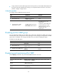
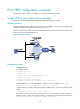
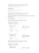
Switch A and Switch B form a VRRP group and use the virtual IP address 10.1.1.111/24 to provide gateway
service for the subnet where Host A resides, as shown in Figure 16.
S
witch A operates as the master to forward packets from Host A to Host B. When Switch A fails, Switch
B takes over to forward packets for Host A.
Figure 16 Network diagram
Configuration procedure
1. Configure Switch A:
# Configure VLAN 2.
<SwitchA> system-view
[SwitchA] vlan 2
[SwitchA-vlan2] port ten-gigabitethernet 1/0/5
[SwitchA-vlan2] quit
[SwitchA] interface vlan-interface 2
[SwitchA-Vlan-interface2] ip address 10.1.1.1 255.255.255.0
# Create VRRP group 1 on VLAN-interface 2, and set its virtual IP address to 10.1.1.111.
[SwitchA-Vlan-interface2] vrrp vrid 1 virtual-ip 10.1.1.111
# Assign Switch A a higher priority than Switch B in VRRP group 1, so Switch A can become the
master.
[SwitchA-Vlan-interface2] vrrp vrid 1 priority 110
# Configure Switch A to operate in preemptive mode, so it can become the master whenever it
operates correctly, and set the preemption delay to 5 seconds to avoid frequent status switchover.
[SwitchA-Vlan-interface2] vrrp vrid 1 preempt-mode delay 5